Instruction Manual
Pneumatic Grease Pump 15 ℓ
62795
![]()
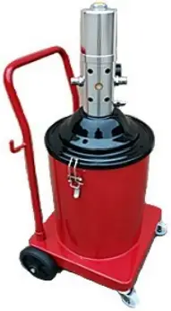
Illustration similar, may vary depending on model
Read and follow the operating instructions and safety information before using for the first time.
Technical changes reserved!
Illustrations, functional steps, and technical data may deviate insignificantly due to continuous further developments.
Updating the documentation
If you have suggestions for improvement or have found any irregularities, please contact us.

The information contained in this document may alter at any time without prior notice. No part of this document may be copied or otherwise duplicated without prior written consent. All rights reserved. WilTec Wildanger Technik GmbH cannot be held liable for any possible mistakes in this operating manual, nor in the diagrams and illustrations shown.
Although WilTec Wildanger Technik GmbH has made every possible effort to ensure that this operating manual is complete, accurate, and up-to-date, errors cannot be ruled out entirely.
If you have found an error or wish to suggest an improvement, we look forward to hearing from you. Send us an e-mail to:
or use our contact form:
https://www.wiltec.de/contacts/
The most recent version of this manual in several languages can be found in our online shop:
https://www.wiltec.de/docsearch
Our postal address is:
WilTec Wildanger Technik GmbH
Königsbenden 12
52249 Eschweiler Germany
To return your goods for exchange, repair, or other purposes, please use the following address. Attention! To allow for a trouble-free complaint or return, it is important to contact our customer service team before returning your goods.
Retourenabteilung
WilTec Wildanger Technik GmbH
Königsbenden 28
52249 Eschweiler Germany
E-mail: [email protected]
Phone: +49 2403 55592-0
Fax: (+49 2403 55592-15)
Introduction
Thank you for choosing to purchase this quality product. To minimise the risk of injury, we ask you to always take some basic safety precautions when using this product. Please read this operating manual carefully and make sure that you understand it.
Keep these operation instructions in a safe place.
This pneumatic lubrication pump/professional grease pump is driven by compressed air and shoots grease at high pressure. This product convinces with its reliability, its low compressed air consumption, the pleasant and easy handling as well as the constant working pressure. It allows you to extend the service life of friction parts of heavy machinery, and that is why it finds application in the automotive industry and other industries.
Safety instructions
- Before using the pump, thoroughly read the operating instructions and all safety instructions and follow them. Failure to obey the information and instructions contained in this manual might lead to property damage and personal injury.
- Observe the warnings and information attached to the device.
- Keep bystanders and children away from your work area.
- Make sure that your work area is well-lit and tidy. A cluttered and poorly lit workplace increases the risk of accidents.
- Wear appropriate protective equipment while working, e.g., work gloves, non-slip work shoes, protective goggles, and a breathing apparatus.
- Do not use the device if you are under the influence of alcohol, drugs, or medicine that impair consciousness.
- Do not make any modifications to the device and only use it for its intended purpose. Improper use or modification might lead to property damage and personal injury.
 Caution! Danger of slipping due to lubricants. Immediately remove spilled or leaked lubricant and dispose of it properly.
- Leaking lubricant can cause environmental damages! Therefore, strictly observe the prescriptions of the water right, clean water law, and environmental law at all times (depending on your country). If you have doubts concerning these prescriptions, read up on the legal regulations.
Technical specifications
| Pressure ratio (without friction losses) | 60:1 |
| Pneumatic cylinder diameter (㎜) | 70 |
| Capacity of the grease pump ( ℓ ⁄min) | 0–0.85 |
| Delivery pression ( ℓ ⁄min) | 300 – 480 |
| Pressure range (㍴) | 5 – 8 |
| Diameter of measured value display (㎜) | 35 |
| Capacity ( ℓ ⁄h) | 15 |
First steps
- Loosen the wing screws on either side of the oil cartridge and tilt the construction by 2030° so that the air enters the lower end of the rubber plate. This can be carefully pulled out without having to dismantle any parts.
- If necessary, inject grease into the oil container. When filling up, make sure that the level mark is not exceeded and that the grease is properly compressed to avoid the formation of bubbles.
- The assembly parts (e.g., lid of oil pump, oil pressure device, etc.) should protrude vertically into the oil storage cylinder so that the rubber plate is pressed against the rough surface. Insert the grease feed pipe into the bottom of the housing. Now tighten the locking screw located next to the tank cover.
- Before putting the pump into operation, check all hoses for damage and immediately replace damaged hoses.
- Then attach the air inlet hose to the air supply quick connector.
- Insert the quick connector into the air inlet port to let in the compressed air and open the pressure control valve. After being pressurised, the pump is likely to start moving up and down and venting air through a sleeve. The oil filling pump starts to work and the lubricant gradually fills the pipeline of the piston oil pump and fills the oil outlet. At this point, connect the oil pump to the high pressure hose of the oil gun. Before connecting, the individual connection parts must be cleaned. Tighten the nut with a wrench to prevent oil leakage.
- When the oil pressure increases gradually and the air pump has been operating for a while, the up-and-down movement of the oil pump will start to slow down until it stops completely. At this moment, the pressure in the oil pump reaches a state of balance and the oil pressure reaches the highest value. As soon as the grease pump is triggered, the oil is expelled from the nozzle. As the grease escapes, the pressure in the oil pump tends to become unbalanced, and the oil pump automatically resumes its up-and-down movement to refill the grease.
- When the pump is filled with grease again, and the oil pressure reaches the highest value, the up-and-down movement stops. The oil pump works in this way repeatedly. When the oil pump stops moving and the oil pressure is at its highest, the connections must be carefully checked for leaks. After having completed the above work, you can proceed with the oil filling.
Important instructions:
To guarantee the longevity of the pump and to achieve optimal and faultless performance, note the following information:
- The compressed air should be filtered to prevent the ingress of dirt particles and additional wear and tear on the pump and its parts.
- The pressure at which the device is used should not exceed 8 bar in order not to impair the integrity and longevity of the individual parts and hoses.
- When using high-pressure grease hoses, make sure that you do not kink or squeeze the hoses or stress them too much by pulling or tensioning them.
- If the device is not in use, the quick connection nipple should be loosened. You should also operate the grease syringe to release the hoses and other components from residual pressure.
- The pump should be oiled at regular intervals.
- Do not use the machine if the grease level is too low, as this may cause overheating and damage to the piston and other parts.
- Clean the pump regularly and remove any grease residues. To do this, also remove the grease syringe to prevent possible damage. Only use cleaning oil to clean the grease channels and make sure that the grease in the pump container is free from contamination.
Troubleshooting
|
Problem |
Possible cause |
Solution |
| 1. Improper lubricant delivery | a) Loose charging bar | Re-fasten charging bar. |
| b) Dirty grease inlet | Find and remove dirt. | |
| c) Lubricating grease too thick | Change lithium grease depending on season: 1–2 times in winter, 2 times in spring and autumn, and 2–3 times in summer. | |
| d) Dirty valve | Remove dirt. | |
| e) Not enough grease in container | Top up with grease. | |
| 2. Pressure loss | a) Worn valve seals | Renew seals. |
| b) Loose slide shoe or screws | Find and fasten loose parts. | |
| 3. Insufficient grease delivery pressure | a) Parts of outlet hose blocked | Find and clean blocked areas. |
| b) Partial blockage of grease channel inside fat syringe | Find and clean blocked areas. | |
| c) Soiling of two one-way valves | Remove piston and clean grease syringe. | |
| Area between shut-off valve and inlet valve clogged | Remove piston and clean grease syringe. | |
| 4. Grease leak when air is deflated | Leaking V-type seal | Renew seal, clean contaminated area. |
| 5. Grease leakage from rotating part of grease syringe | Leaky butyl rubber seal | Renew seal, clean contaminated area. |
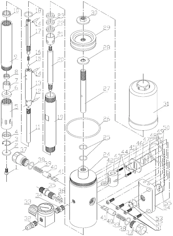
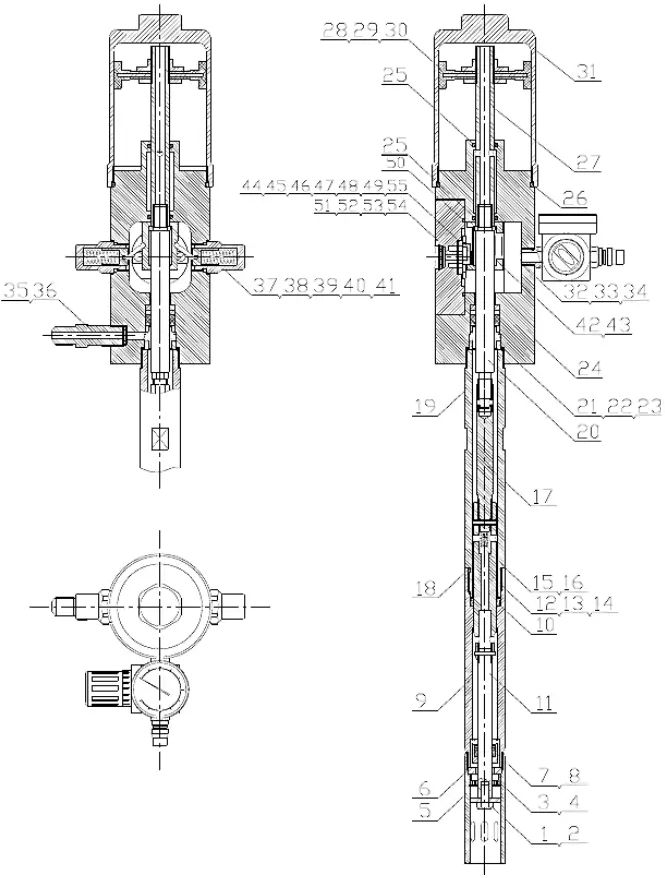
Exploded view and parts list
|
№ |
Name |
№ |
Name |
|
1 |
Hexagon bolt |
29 |
Piston |
|
2 |
Lifting plate |
30 |
Hexagon flat nut |
|
3 |
Lock ring |
31 |
Cylinder |
|
4 |
Filter insert |
32 |
Quick connector |
|
5 |
Oil inlet pipe |
33 |
Pressure control valve |
|
6 |
Check valve cover |
34 |
Pressure regulating valve connection |
|
7 |
Check valve |
35 |
Air supply connection |
|
8 |
Shaft seal |
36 |
Gasket |
|
9 |
Pump body |
37 |
Return spring holder |
|
10 |
Shaft seal |
38 |
O-ring |
|
11 |
Lifting rod |
39 |
Return spring |
|
12 |
Elastic cylinder pin |
40 |
Return spring sleeve |
|
13 |
Check valve housing |
41 |
Check valve flap |
|
14 |
Elastic cylinder pin |
42 |
Push ring of quick release sleeve |
|
15 |
Steel ball |
43 |
Quick release sleeve |
|
16 |
Straight check valve |
44 |
Pressure screw |
|
17 |
Connecting lever |
45 |
Leaf spring |
|
18 |
O-ring |
46 |
Rabbet of valve block |
|
19 |
Oil hose |
47 |
Air distribution unit |
|
20 |
Output rod of compressed air pump |
48 |
Valve plate |
|
21 |
Oil overflow spacer |
49 |
O-ring |
|
22 |
Shaft seal |
50 |
O-ring |
|
23 |
Washer |
51 |
Hexagon socket screw |
|
24 |
Air pump body |
52 |
Lock ring |
|
25 |
O-ring |
53 |
Sleeve |
|
26 |
O-ring |
54 |
Check valve housing |
|
27 |
Piston rod |
55 |
Gasket |
|
28 |
Flat nut |
Important Note:
Reproduction and any commercial use (of parts) of this operating manual, requires a written permission of WilTec Wildanger Technik GmbH.
https://www.XPOtool.com
The Tool Experts
Item 62795
05 2022-1