![]() One RS-232 Cable with Drivers
One RS-232 Cable with Drivers
Installation Guide
Reproduction of the contents of this copyrighted document, in whole or part, without written permission of 0N3 S.r.l., is prohibited.
User Manual available on
Contents
DIMENSION

INSTALLATION
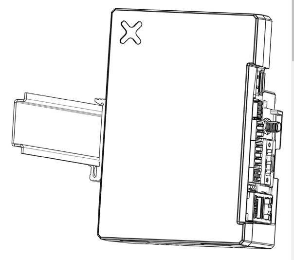 The Xbase is suitable for mounting on a DIN rail.
Suitable to be used with Model X5 Compact Enclosed Handheld Programmable Controller
The products have been designed for use in industrial environment in compliance with the 2014/53/ EU, 2011/65/EC directives
The products have been designed in compliance with:
| EN ISO 13849-1 :2015 EN ISO 1349-2: 2012 EN 61010-1:2010 + A1:2019 + AC:2019-04 EN IEC 61010-2-201 : 2018 ETSI EN 300 328 V2.1.1:2016 ETSI EN 301 893 V2.1.1:2017 ETSI EN 301 489-1 V2.1.1 ETSI EN 301 489-17 V2.1.1 |
EN61000-6-2:2017 EN61000-6-4:2007+A1:2011 EN61000-4-2:2009 EN61000-4-3:2006+A2:2010 EN61000-4-4:2012 EN61000-4-5:2006 EN61000-4-6:2009 EN61000-4-8:2013 EN61000-4-29:2000 EN62311:2008 |
The installation of these devices into the residential, commercial and light-industrial environments is allowed only in the case that special measures are taken in order to get theconformity to IEC 61000-6-3.
OVERVIEW

- Serial Port
- Power Supply
- Ethernet Port #1
- Ethernet Port #0
- USB Host
- Plug-in Expansion Slot
- SD Card Slot
- Selector Outputs
- Safety Module Outputs
- Auxiliary I/O
- Status LEDs
- Wi-Fi Antenna connector*
connect the supplied antenna via appropriate cable
The position of the antenna must always respect the minimum distance of 20cm from the human body for the protection of human health
All ports are SELV (Safety Extra – Low Voltage) according European Standard and Class 2 according to UL Standards
POWER SUPPLY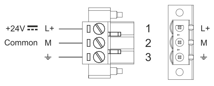 DC Power Connector, Female – R/C Terminal Blocks (XCFR2), manufactured by Weidmüller, Cat. No. BLZ 5.08, torque 4.5 lb-in (0.5 Nm)
Extra low voltage power supply / Limited power source.
Do not open the rear cover when the power supply is applied.
WARNING: Do not disconnect when energized.
FACTORY SETTINGS
ETH0 / WAN: DHCP
ETH1 / LAN: IP Address 192.168.0.1 Subnet mask: 255.255.255.0
Settings: https://192.168.0.1/machine_config
Username: admin
Password: admin
The unit must always be grounded to earth. Earth connection will have to be done using either the screw or the faston terminal located near the power supply terminal block. Also connect to ground the terminal 3 on the power supply terminal block.
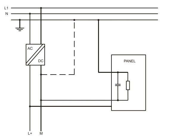 Ensure that the power supply has enough power capacity for the operation of the equipment.
DISPOSAL OF BATTERIES
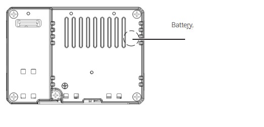 Dispose of batteries according to local regulations.
This device cannot be disposed of as a domestic waste but according to WEEE European Directive 2012/19/EU
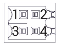
Connections
POWER SUPPLY
| Pin | |
| 1 | Positive rail of auxiliary Digital Input |
| 2 | Negative rail of auxiliary Digital Input |
| 3 | Pairing Lamp command – Output |
| 4 | Diagnostic output of safety logic |
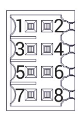
SAFETY OUTPUTS
| Pin | |
| 1 | Safety contact “A1”. Emergency Stop push-button contact #1 |
| 2 | Safety contact “A2”. Emergency Stop push-button contact #1 |
| 3 | Safety contact “B1”. Emergency Stop push-button contact #2 |
| 4 | Safety contact “B2”. Emergency Stop push-button contact #2 |
| 5 | Safety contact “C1”. Enabling Device contact # |
| 6 | Safety contact “C2”. Enabling Device contact #1 |
| 7 | Safety contact “D1”. Enabling Device contact #2 |
| 8 | Safety contact “D2”. Enabling Device contact #2 |
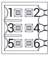
 SELECTOR OUTPUT
| Pin | |
| 1 | Positive supply of solid state outputs |
| 2 | Negative supply of solid state outputs |
| 3 | State Selector OUT – B0 |
| 4 | State Selector OUT – B1 |
| 5 | State Selector OUT – B2 |
| 6 | State Selector OUT – B3 |
 SERIAL PORT
| RS-232 | |
| Pin | |
| 1 | RX |
| 2 | TX |
| 3 | CTS |
| 4 | RTS |
| 5 | +5V Output |
| 6 | GND |
| 7 | |
| 8 | SHIELD |
| RS-422, RS-485 | |
| Pin | |
| 1 | CHB- |
| 2 | CHACHB+ |
| 3 | CHA+ |
| 4 | +5V Output |
| 5 | GND |
| 6 | |
| 7 | |
| 8 | SHIELD |
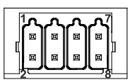 To operate in RS-485 pins 1-2 and 4-3 must be connected externally
STATUS LEDS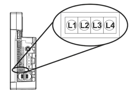
| Pin | ||
| 1 | Red | CPU error |
| 2 | Green | CPU run |
| 3 | Red | Xbase paired |
| 4 | Green/ | Power Supply |
![]() MANXBASE – Version 2.02 19.02.2024
MANXBASE – Version 2.02 19.02.2024
© 2024 0N3 s.r.l. – Subject to change without notice
0N3 S.r.l. – Verona, Italy (Administrative and Operational headquarters)
www.exorint.com