![]() WESCO INDUSTRIAL PRODUCTS, LLC
WESCO INDUSTRIAL PRODUCTS, LLC
Instruction Manual
ElectricOfficeLift
Part Number: 272468
Contents
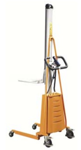
272468 Electric Office Lift
Note: Operator MUST read and understand these operating instructions before using this Lifter.
©Copyright 2018 WESCO Industrial Products, LLC. Specifications subject to change. Not responsible for errors or omissions
Instruction Manual
ATTENTION: TO INSURE SAFE AND EASY USE OF YOUR WESCO LIFTER, READ THESE INSTRUCTIONS ENTIRELY BEFORE USING.
WARNING: The battery in this product contains lead. The State of California under Proposition 65 has determined that exposure to lead is known to cause cancer or birth defects or other reproductive harm. Please wash hands after use.
GENERAL INFORMATION
1.1 DESCRIPTION
Thank you for purchasing a Wesco Electric Office Lift. This lifter is designed for transporting and vertical lifting. The lift features a 1 year warranty covering manufacturing defects. Wesco reserves the right to repair or replace defective parts or the entire unit as required to correct any defective components. This warranty expressly excludes damage due to normal wear and or misuse.
1.2 SPECIFICATIONS
| Model | 272468 | |
| Capacity | 220 lbs | |
| Load Center | (C) | 9.25” |
| Lowered Height | (H1) | 5” |
| Raised Height | (H2) | 66” |
| Platform Size | (L1 X W) | 18” x 23” |
| Overall Dimensions………………………………….. (L X W X H ) | 32” x 23.5” x 78” | |
| Front Wheel | (Ød) | 2.75” x 1.25” (Hard Rubber) |
| Rear Wheel | (ØD) | 5” x 1.25” (Hard Rubber) |
| Battery | 24V | |
| Weight | 147 lbs | |
Materials and specifications are subject to change without notice.
Items in Figure 1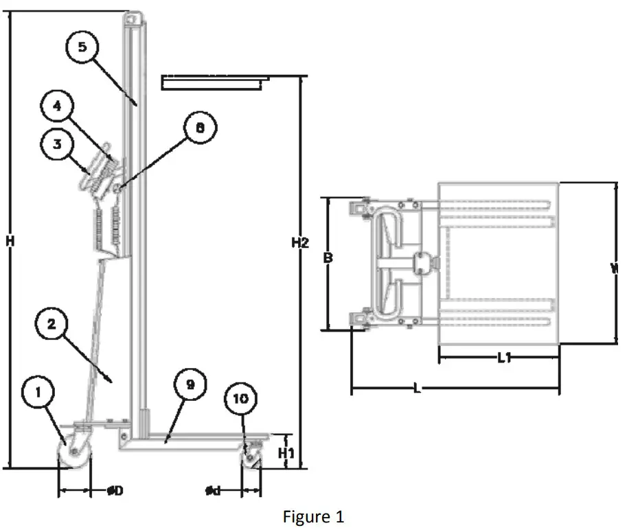
- Rear Wheel
- Electric Control of Transmission Box
- Handrails
- Movable Hand Panel
- Aluminum Alloy Pole
- Safety Belt
- Platform (Various Accessories)
- Socket for Charger
- Chassis
- Front Wheel
PRE-OPERATION ASSEMBLY
Items Numbers reference Drawings/List on Pages 7-8
- Check the parts are complete, in good condition and appearance.
- Connect the fixed fork (30a) by bolt (32) to the safety belt (29), downward/upward bearing seat (41) separately, without loosening and ensure the safety belt is clamped firmly.
- Switch the power ON without load, (Buzzer may beep, switch off/on again, beep will stop.); operate the hand panel (19), platform (30) lifts smoothly up to the max. height, keep it still, and then lower it to the bottom position.
- Repeat step 3 with a rated load, the platform should lift smoothly to the max. height, stop without slipping, and lower smoothly to the bottom position.
- The maintenance-free battery, which is provided with the lifter, has been initially charged full. However the battery may require some recharging before use.
SAFETY INFORMATION (WARNINGS)
- Use only on smooth surfaces.
- Do not overload, make sure load is distributed uniformity.
- Buzzer will beep to alert of a low battery, charge as soon as possible or the battery can be damaged.
- Ensure that the input voltage of the charger complies with local power net voltage.
- Do not put hands/feet in contact of chain or other moving parts.
- Do not to carry out long hours of continuous work under extreme loads, this can lead to overheating of the motor and panel.
- The working life of the lift can be greatly prolonged by operating it under 0.7 times the maximum nominal load.
- Keep the electric control commission box closed before operation.
MAINTENANCE
Daily
Check the smoothness and stability of the platform functions, raising and lowering.
Monthly
- Check for any deformation, connection loosening, wearing and abnormal sounds from:
– Connecting bolts
– Wheels
– Rolling bearings
– Transmission chain
– Pole
– Safety belt
– Structure parts
– Moving parts. - Check the jiggling, wearing, lubricating, and loosening of:
– Chain
– Sprocket wheel
– Chain-trolley
– Connecting bolts
– Inner transmission box. - Adequately grease parts in need.
Every 3 Months
Check the control panel, charger, battery and electric control wiring if any loosening inner transmission box and the inner box cleaning.
OPERATION
Transition/Loading/Unloading
- Lock casters before loading or unloading at any height.
- Distribute load uniformly when loading and unloading; load should not stretch over platform.
- Maintain control during transportation to avoid any tilting of the unit.
- Lower the platform to the lowest position when the loaded lifter is about to begin transportation.
Raising and Lowering the Platform
- Make sure adequate space is available for operation of the lifter.
- Lock the wheels, and switch power on.
- Press the UP button on the panel, the platform will climb smoothly to the needed height. Then release the button and the platform stops at its current height.
- Follow the instructions listed above for loading/unloading the lifter.
- When finished unloading at a raised height, press the DOWN button and the platform will descend smoothly. Release the Down button at any height and the platform will stop descending.
- The elevator is designed to with an overload protection function. Whenever the load surpasses 25% of the rated capacity, the platform will not lift; the lifter will not be able to carry out the functions of raising, lowering or unit transportation.
- The lifter is designed with a low power protection function. If the battery power is not sufficiently charged for operation during loaded raising/lowering, the buzzer beeps for 50 seconds continuously. Then it will cut off the power circuit automatically, with indicator light flashing. The operator will lower the platform to the lowest position during this time.
Battery
- High performance, maintenance-free, sealed, acidic-lead, storage battery is selected to power the lifter. It has a low discharge ability, safe, easy mounting and change-over, and can be used under the ambient temperature range of 5ºF – 122ºF (-15ºC–50ºC).
- The life of the battery is dependent on proper use. The working life can be greatly shortened when repeatedly using it at low voltage, and even burn the control element. The lifter is designed with a low voltage protection function in the electric controls. While the lifter is operating under low voltage while lifting/lowering, the buzzer will beep for 50 seconds continuously and then cut off the power supply. The operator will need to charge the battery as soon as possible.
Charger
- A high performance charger is provided with the lifter so that the battery can be charged at any handy power terminal. Be sure the voltage of the local power net is meets the needs of the inlet voltage of the charger.
- When charging, make sure to switch off power to the lifter, connect charger source pin and power terminal socket, the red indicator of source power of the charger is lit up, while the charging status green indicator is lit, that means the battery is in the status of charging; and when the green indicator faded, that means the battery is charged full. Generally, the charging period takes 10-12 hours.
- Shall the charged battery show low voltage status during heavy duty job. Probably the battery is damaged or the charger is in trouble.
TROUBLE SHOOTING
| No | Problem | Causes |
Solutions |
| 1 | Power On, pressing UP button, platform does not lift up | 1. Power switch damage | Check and replace |
| 2. Wire off | Check and connect | ||
| 3. Battery dead or damaged | Charge or replace | ||
| 4. Button malfunction or wire disconnected | Check and replace | ||
| 5. Panel fuse burnt out | Replace | ||
| 6. Motor damaged | Check or replace | ||
| 7. Overloaded | Partially unload | ||
| 8. Lowest position traveling switch fail | Check or replace | ||
| 2 | Press UP button, unit lifts slowly or will not lift | 1. Battery low or discharged | Recharge |
| 2. Motor trouble, RPM lowered | Check or replace | ||
| 3. Panel failure | Readjust panel | ||
| 3 | Platform cannot climb to max. height | 1. Inner guiding rail blocked | Clear obstruction and lubricate |
| 4 | Platform climbs to max. height, but will not lower | 1. DOWN button failure | Check or replace |
| 2. Traveling switch of inner panel failure | Check or replace | ||
| 3. Panel damage | Check or replace | ||
| 4. Safety belt fail, not working | Check or replace | ||
| 5 | Safety belt fails to protrude or retrieve | 1. Ratchet structure of the device failure | Check or replace |
| 2. Spring of inner device damage | Check or replace | ||
| 6 | Battery charged, but platform lifts slowly or cannot lift up | 1. Insufficient charging | Recharge |
| 2. Battery damage | Replace battery | ||
| 3. Charger fail | Check or replace the charger | ||
| 7 | Obvious low voltage, but buzzer does not beep to warn | 1. Wire off or buzzer fail | Check or replace |
| 2. Buzzer circuit damage | Check or replace | ||
| 8 | Abnormal sound from platform up/down transmission | 1. Chain elongated | Adjust to proper elongation |
| 2. Sprocket loosening or shift | Check or replace | ||
| 3. Sprocket wheel damage | Check or replace | ||
| 4. Other commissioning part worn out, deformed | Check or replace |
NOTE: DO NOT ATTEMPT TO REPAIR THE LIFTER UNLESS YOU ARE TRAINED AND AUTHORIZED TO DO SO.
ELECTRICAL DIAGRAMS
7.1 Circuit Diagram (Units Manufactured After June 2014) 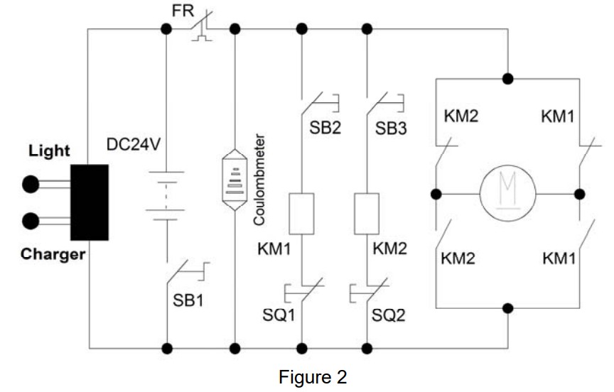
| Item | Description |
| FR | Thermal Cutoff |
| SB1 | Power Supply Switch |
| SB2 | Up Limit Switch |
| SB3 | Down Limit Switch |
| KM1 | Up Contactor |
| KM2 | Down Contactor |
| SQ1 | Up Limit Switch |
| SQ2 | Down Limit Switch |
7.2 Electric Panel Diagram (Units Manufactured After June 2014)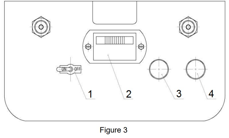
| Item | Description |
| 1 | Power Supply Swich |
| 2 | Power Indication |
| 3 | Charging Status (Charged) |
| 4 | Charging Status (Charging) |
7.3 Circuit Diagram (Units Manufactured Before June 2014)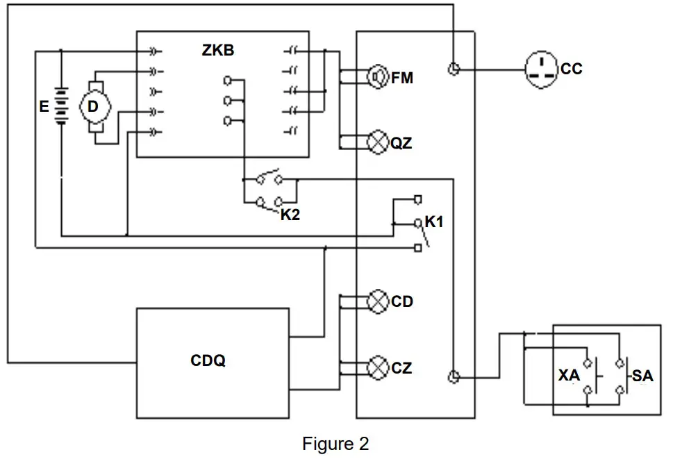
| Item | Description |
| E | 24V DC Supply |
| CC | Socket of Charger |
| QZ | Cut-Off Indicator |
| CZ | Charging Status |
| XA | Down Button |
| K2 | Up/Down Limit Switch |
| CDQ | Charger |
| D | DC Motor |
| FM | Buzzer |
| CD | Charger Supply |
| SA | Up Button |
| K1 | Power Supply Switch |
| ZKB | Main Control Circuit Board |
7.4 Electric Panel Diagram (Units Manufactured Before June 2014)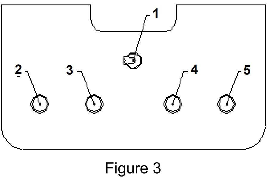
| Item | Description |
| 1 | Power Switch |
| 2 | Cut-Off Indicator |
| 3 | Charging Status |
| 4 | Buzzer |
| 5 | Charger Power Supply |
PART INFORMATION (UNITS MANUFACTURED AFTER JUNE 2014)
8.1 FRAME PART DIAGRAM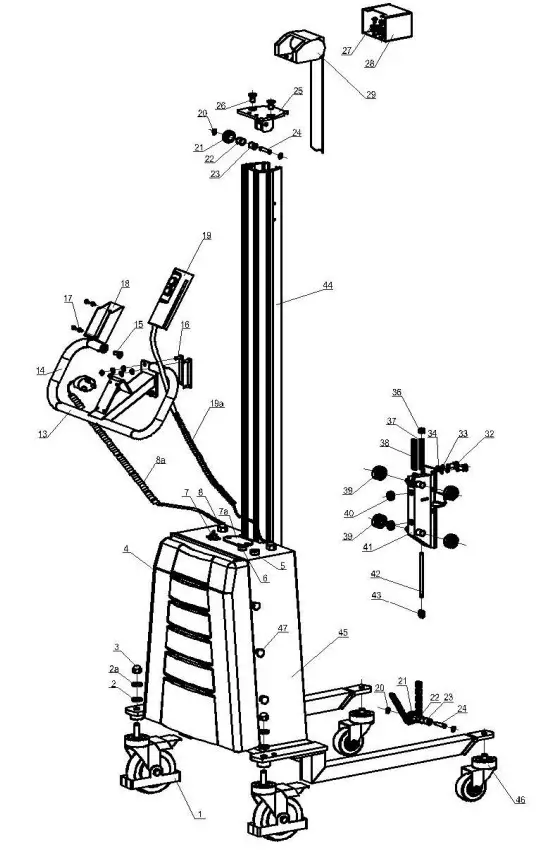 8.2 FRAME PART LIST
| Item | P/N | Description | Qty. |
| 1 | 273111 | Rear Swivel Caster Unit (5”) | 2 |
| 2 | Plain Washer 12 | 2 | |
| 2A | Spring Washer 12 | 2 | |
| 3 | Hex Domed Cap Nut M12 | 4 | |
| 4 | 273958 | Electric Box Cover | 1 |
| 5 | Charging Indicator-Green | 1 | |
| 6 | Charging Indicator-Red | 1 | |
| 7 | Toggle Switch | 1 | |
| 7A | Battery Indicator | 1 | |
| 8 | Wire Fixing Nut | 2 | |
| 8A | Charger Adjustable Wire & Plug | 1 | |
| 10 | Plain Washer 6 | 11 | |
| 11 | Spring Washer 6 | 11 | |
| 12 | Hex Domed Cap Nut M6 | 4 | |
| 13 | Handle, Weld | 1 | |
| 14 | PU-Buffer | 2 | |
| 15 | Countersunk Head Screw M8x20 | 4 | |
| 16 | Mount Plate | 2 | |
| 17 | Countersunk Head Screw M4x10 | 14 | |
| 18 | 273189 | Control Handle Seat | 1 |
| 19 | 273186 | Control Handle | 1 |
| 19A | Adjustable Wire for Control Handle | 1 | |
| 20 | Retaining Ring 8-Shaft | 4 | |
| 21 | 273959 | Load Chain Guide Wheel | 3 |
| 22 | 273962 | Copper Bush 15×1 | 3 |
| 23 | 273963 | Spacer Tube | 3 |
| 24 | 273946 | Shaft-Load Chain Guide Wheel | 3 |
| 25 | Top Block Cover | 1 | |
| 26 | Countersunk Head Screw M10x20 | 2 | |
| 27 | Socket Head Cap Screw M6x12 | 4 | |
| 28 | Protection Steel Cover-Safety Belt | 1 | |
| 29 | 273193 | Safety Belt Unit | 1 |
| 31 | Socket Head Cap Screw M6x20 | 3 | |
| 32 | Socket Head Cap Screw M10x20 | 2 | |
| 33 | Spring Washer 10 | 2 | |
| 34 | Plain Washer 10 | 2 | |
| 36 | Hexagonal Locking Nut M8 | 2 | |
| 37 | 273966 | Load Chain Buffer Spring | 1 |
| 38 | Load Chain | 1 | |
| 39 | Ball Bearing 6202 | 4 | |
| 40 | Guide Wheel | 2 | |
| 41 | 273967 | Mounting Seat for Roller, Weld | 1 |
| 42 | Bolt, Load Chain End | 1 | |
| 43 | Load Chain Link | 6 | |
| 44 | Aluminum Mast | 1 | |
| 45 | Main Frame, Weld | 1 | |
| 46 | 273187 | Front Swivel Caster Unit (3”) | 2 |
| 47 | Combination Screw | 6 |
8.3 HANDLE & PLATFORM PART DIAGRAM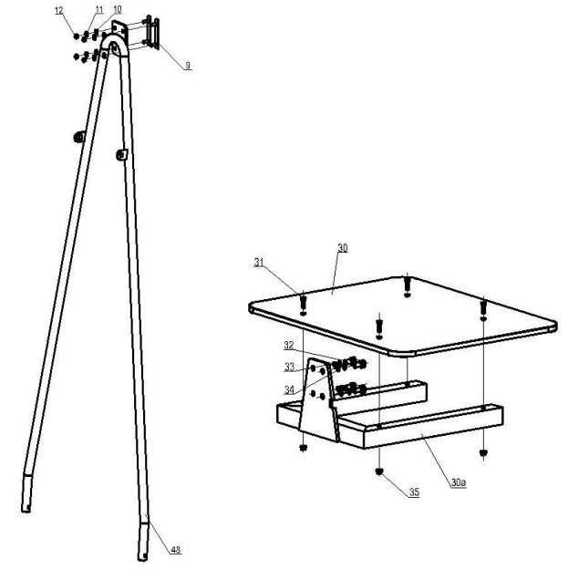 8.4 HANDLE & PLATFORM PART LIST
|
Item |
P/N | Description |
Qty. |
| 9 | Plate for Handrail | 2 | |
| 10 | Plain Washer 6 | 4 | |
| 11 | Spring Washer | 4 | |
| 12 | Hex Domed Cap Nut | 4 | |
| 30 | Platform | 1 | |
| 30A | Base Frame, Weld, Platform | 1 | |
| 31 | Socket Head Cap Screw M6x20 | 4 | |
| 32 | Socket Head Cap Screw M10x20 | 4 | |
| 33 | Spring Washer 10 | 4 | |
| 34 | Plain Washer 10 | 4 | |
| 35 | Hex Flange Self Locking Nut M6 | 4 | |
| 48 | Supporting Handrail, Weld | 1 |
8.5 ELECTRICAL BOX PART DIAGRAM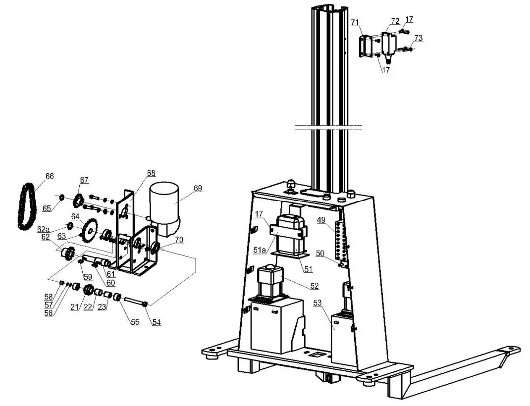 8.6 ELECTRICAL BOX PART LIST
| Item | P/N | Description |
Qty. |
| 17 | Countersunk Head Screw M4x10 | 14 | |
| 21 | Load Chain Guide Wheel | 3 | |
| 22 | Copper Bush 15×1 | 3 | |
| 23 | Spacer Tube | 3 | |
| 49 | Terminal Block | 1 | |
| 50 | Circuit Breaker-Automatic Reset | 1 | |
| 51 | 273188 | Charger 24VDC | 1 |
| 51A | Fixing Plate for Charger | 1 | |
| 52 | 273968 | Contactor | 2 |
| 53 | Battery 12V12Ah | 2 | |
| 54 | 273965 | Socket Head Cap Screw M8x60 | 1 |
| 55 | Bushing | 2 | |
| 56 | Plain Washer 8 | 1 | |
| 57 | Spring Washer | 1 | |
| 58 | Nut M8 | 1 | |
| 59 | Flat Key 6x6x10 | 1 | |
| 60 | Flat Key 5x5x14 | 1 | |
| 61 | 273957 | Transmission Shaft | 1 |
| 62 | Sprocket Wheel-12 Teeth | 1 | |
| 62A | Retaining Ring | 1 | |
| 63 | Stopper Screw M5x10 | 1 | |
| 64 | 273955 | Sprocket Wheel 23 teeth | 1 |
| 65 | Retaining Ring | 1 | |
| 66 | Transmission Chain | 1 | |
| 67 | 273956 | Sprocket Wheel-13 Teeth | 1 |
| 68 | Reducer Seat | 1 | |
| 69 | 273185 | Worm Gear Box Assembly | 1 |
| 70 | Ball Bearing 6002 | 2 | |
| 71 | Seat for Limit Switch | 2 | |
| 72 | 273634 | Limit Switch | 2 |
| 73 | Countersunk Head Screw M4x25 | 4 | |
| * | Stopper Screw M5x6 (For Sprocket Wheel-13 Teeth) | 1 |
*Not shown, used in old design
PART INFORMATION (UNITS MANUFACTURED BEFORE JUNE 2014)
9.1 FRAME PART DIAGRAM 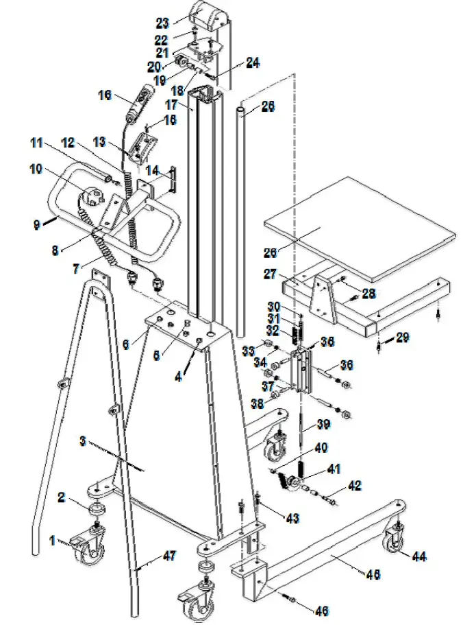 9.2 FRAME PART LIST
| Item | P/N | Description |
Qty. |
| 1 | 273111 | Rear Wheel | 2 |
| 2 | Washer | 2 | |
| 3 | Electric Box | 1 | |
| 4 | Indicator | 3 | |
| 5 | 273182 | Power Supply Switch | 1 |
| 6 | Buzzer | 1 | |
| 7 | Spring Wire | 1 | |
| *8 | 273183 | Handrail | 1 |
| *9 | 273075 | Protective Cover | 2 |
| 10 | Charger Pin | 1 | |
| 11 | KIT A | Sunk Bolt | 2 |
| 12 | 273143 | Spring Wire | 1 |
| 13 | 273142 | Electric Control Seat | 1 |
| 14 | Connecting Bolt | 4 | |
| 15 | KIT A | Sunk Bolt | 4 |
| 16 | 273122 | Hand Electric Panel | 1 |
| 17 | Pole | 1 | |
| **18 | 273076 | Bush | 2 |
| **19 | 273077 | Oil-Free Bearing | 2 |
| **20 | 273078 | Upper Trolley | 1 |
| **21 | KIT B | Upper Trolley Seat | 1 |
| 22 | KIT A | Sunk Bolt | 2 |
| 23 | 237099 | Safety Belt | 1 |
| **24 | KIT B | Hex Bolt | 1 |
| 25 | Chain Bush | 1 | |
| 26 | Platform | 1 | |
| 27 | Fixed Racket | 1 | |
| 28 | KIT A | Inner Hex Bolt | 4 |
| 29 | Inner Hex Bolt | 4 | |
| 30 | KIT A | Hex Nut M8 x 1.25 | 1 |
| 31 | 273144 | Spring | 1 |
| 32 | 273132 | Precision Roller Chain | 1 |
| 33 | Bearing | 4 | |
| 34 | Interval Ring | 4 | |
| 35 | Up/Down Bearing Seat | 1 | |
| 36 | Pin Shaft | 2 | |
| 37 | Small Trolley Shaft | 2 | |
| 38 | Small Trolley | 2 | |
| 39 | 273145 | Chain Bolt | 1 |
| 40 | KIT A | Nut | 1 |
| 41 | 273184 | Lower Trolley | 1 |
| 42 | Hex Bolt | 1 | |
| 43 | KIT A | Hex Bolt | 4 |
| 44 | 273112 | Front Wheel | 2 |
| 45 | Front Wheel Fork | 2 | |
| 46 | KIT A | Hex Bolt | 2 |
| 47 | 273110 | Pole Pulling Pipe | 1 |
*Items 18‐21 & 24 are included in Kit detailed below
** Item 9 Protective Cover included with Item 8 Handrail (P/N 273183)
REPLACEMENT KIT LIST
| Kit | Item | P/N | Description |
Qty. |
| A | 273071 | HARDWARE KIT | 1 | |
| 11 | Sunk Bolt | 2 | ||
| 15 | Sunk Bolt | 4 | ||
| 22 | Sunk Bolt | 2 | ||
| 28 | Inner Hex Bolt | 4 | ||
| 30 | Hex Nut M8 x 1.25 | 1 | ||
| 40 | Nut | 1 | ||
| 43 | Hex Bolt | 4 | ||
| 46 | Hex Bolt | 2 | ||
| 202 | Shown on Page 14 | Nut | 1 | |
| 203 | Capacity Adjustment Bolt | 1 | ||
| 208 | Hex Bolt | 2 | ||
| 211 | Nut | 2 | ||
| 219 | Top Prick Fixing Bolt | 3 | ||
| B | 273078 | UPPER TROLLEY SEAT ASSEMBLY | 1 | |
| 18 | Bush | 2 | ||
| 19 | Oil-Free Bearing | 2 | ||
| 20 | Upper Trolley | 1 | ||
| 21 | Upper Trolley Seat | 1 | ||
| 24 | Hex Bolt | 2 |
Note: Items within kits specify quantity included per kit
9.3 ELECTRICAL BOX PART DIAGRAM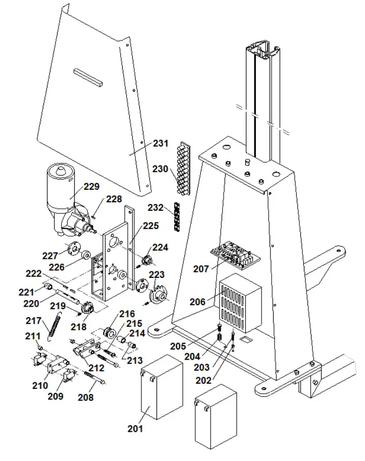 9.4 ELECTRICAL BOX PART LIST
|
Item |
P/N | Description |
Qty. |
| 201 | 273072 | (Storage) Battery | 2 |
| 202 | KIT B | Nut | 1 |
| 203 | KIT B | Capacity Adjust Bolt | 1 |
| 204 | Spring | 1 | |
| 205 | Adjustable Bolt | 1 | |
| 206 | 273073 | Charger | 1 |
| 207 | 273074 | Circuit Board | 1 |
| 208 | KIT B | Hex Bolt | 2 |
| 209 | 273178 | Traveling Switch | 2 |
| 210 | Traveling Switch Seat | 1 | |
| 211 | KIT B | Nut | 2 |
| 212 | Flexible Racket | 1 | |
| 213 | Bush | 1 | |
| 214 | Oil-Free Bearing | 1 | |
| 215 | Sunk Bolt | 1 | |
| 216 | Flexible trolley | 1 | |
| 217 | 273180 | Pull Spring | 1 |
| 218 | 273176 | Transmission Chain Wheel | 1 |
| 219 | KIT B | Top Fixing Bolt | 3 |
| 220 | 273175 | Transmission Shaft | 1 |
| 221 | 273174 | Interval Ring | 1 |
| 222 | 273177 | Plain Pin | 2 |
| 223 | 273173 | Big Chain Wheel | 1 |
| 224 | Motor Chain Wheel | 1 | |
| 225 | 273170 | Motor Seat | 1 |
| 226 | 273172 | Bearing | 2 |
| 227 | 273171 | Bearing Lid | 2 |
| 228 | Plain Pin | 1 | |
| 229 | 273179 | Motor | 1 |
| For Units Manufactured Before 12/2014) | |||
| 273185 | Motor | 1 | |
| (For Units Manufactured After 12/2014) | |||
| 230 | Electric Box Lid | 1 | |
| 231 | 273134 | Link Chain | 1 |
REPLACEMENT KIT LIST
|
Kit |
Item | P/N | Description |
Qty. |
| A | 273071 | HARDWARE KIT | 1 | |
| 11 | Sunk Bolt | 2 | ||
| 15 | Sunk Bolt | 4 | ||
| 22 | Sunk Bolt | 2 | ||
| 28 | Inner Hex Bolt | 4 | ||
| 30 | Hex Nut M8 x 1.25 | 1 | ||
| 40 | Nut | 1 | ||
| 43 | Hex Bolt | 4 | ||
| 46 | Hex Bolt | 2 | ||
| 202 |
Shown on Page 14 |
Nut | 1 | |
| 203 | Capacity Adjustment Bolt | 1 | ||
| 208 | Hex Bolt | 2 | ||
| 211 | Nut | 2 | ||
| 219 | Top Prick Fixing Bolt | 3 |
Note: Items within kits specify quantity included per kit
©Copyright 2018 WESCO Industrial Products, LLC. Specifications subject to change. Not responsible for errors or omissions. ![]()