![]()
MAGLOC100M Magnetic Lock Wiring Instruction
Contents
MAGLOC100M Mortise Mount Magnetic Lock Wiring
A. 12VDC input :
Required power 0.5 amp (Maximum).
Connect the ground (-) lead from a 12VDC power source to the white wire of PCB.
Connect the positive (+) lead from a 12VDC power source to the blue wire of PCB.
Check jumper for 12VDC operation.
B. 24VDC input :
Required power 0.25 amp (Maximum).
Connect the ground (-) lead from a 24VDC power source to the white wire of PCB.
Connect the positive (+) lead from a 24VDC power source to the blue wire of PCB.
Check jumper for 24VDC operation.
C. Contacts:
Reed switch dry contacts are rated 0.5 Amp at 30VDC/AC for safe operation, do not exceed this rating.
If you required a normally open switch, connect the wires from the system to the black wire and green wire of PCB
If you required a normally closed switch, connect the wires from the system to the black wire and red wire of PCB.
Important!
If the power switch is not wired between the DC source voltage and the magnet, it will take a longer time to de-energize the magnet, simulating residual magnetism. (see below)

Printed Circuit Board Schematic

Mortise mounted
APPLY FOR MAGLOC100M (USE FOR MAGNET/SLIDING DOORS – W/O MOUNTING PLATE)

APPLY FOR MAGLOC100M (USE FOR MAGNET/SLIDING DOORS)
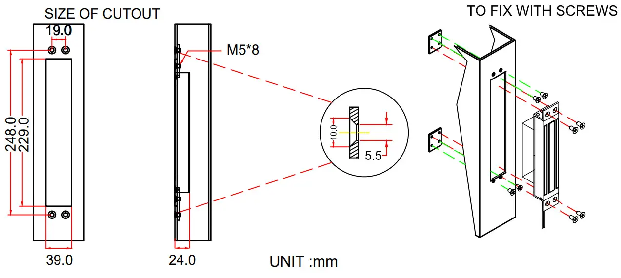
APPLY FOR MAGLOC100M (USE FOR ARMATURE PLATE/SLIDING DOORS)

MAGLOC100M