Contents
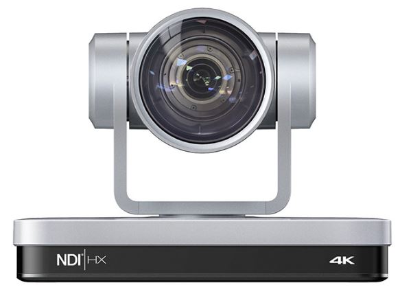
VLV UV430 Professional Camera
Preface
This manual is to ensure that the user can use the product properly and avoid danger while operating. Before using this product, please read the user manual carefully and keep it properly for future reference
Overview
This manual is about PTZ camera operation
Graphic Symbols
Description of graphic symbols used in this manual
| Description |
| This symbol indicates that the words are clarification or supplement to this article. |
| This symbol indicates that negligence of the instructions may lead to mishandling that may cause injury or property damage. |
| This symbol indicates a risk that may result in damage to this machine or documents.
Follow the instructions to avoid property damage. |
Attention
This manual introduces functions, installations and operations for this product in details. Please read this manual carefully before installation and use.
Precautions:
This product can only be used in the specified conditions in order to avoid any damage to the camera:
- Do not expose the product to rain or moisture.
- To prevent the risk of electric shock, do not open the case. Installation and maintenance should only be carried out by qualified technicians.
- Do not use the product beyond the specified temperature, humidity or power supply specifications.
- Please use a soft dry cloth to clean the camera. If the camera is very dirty, clean it with diluted neutral detergent; do not use any type of solvents, which may damage the surface.
Electrical Safety:
Installation and use of this product must strictly comply with local electrical safety standards.
Transportation:
Avoid any stress, vibration, or moisture during transportation, storage, installation and operation
Installation:
- Do not rotate the camera head violently, otherwise it may cause mechanical failure;
- This product should be placed on a stable desktop or other horizontal surface. Do not install the product obliquely, otherwise it may display inclined image;
- Ensure there are no obstacles within rotation range of the holder.
- Do not power on before completely installation.
Do Not Dismantle Camera:
We are not responsible for any unauthorized modification or dismantling.
Magnetic Interference
Electromagnetic fields at specific frequencies may affect the video image. This product is Class A. It may cause radio interference in household application. Appropriate measure is required
Quick Start
Interface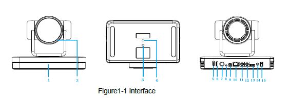
- Receiving Light
- Lens
- Fixation Hole
- Tripod Screw Hole
- HDMI Jack
- USB2.0
- SDI
- Audio In
- Rotary Dip Switch
- Network Jack
- RS232 Input
- RS232 Output
- RS422/RS485 Jack
- DC12V Power Socket
- Power Switch
When using the camera, please put the plastic pad on the center bottom of the device
Power-on Self-Test
Power on
Connect the device to power socket with a DC12V power adapter.
Self-Test
After powering on, the receiver light will start flashing and the camera will do a brief pan-tilt tour and return to the home position. When the light stops flashing, the self-test is finished.
- The default address of the remote control is 1#. When the menu restores the default setting, the address of IP remote control will restore 1#.
- If preset 0 is set, the camera will return to the preset 0 position after self-test
Video Output
This series camera can output video through network, HDMI, SDI, and USB2.0.
Network Output
- Network connection: Shown as diagram 1.1 #15
- Log in: You can reach the Web Interface by typing in the camera’s IP
address(default 192.168.5.163) into a web browser. To log in, type in “admin” into the username and password fields. From the Web Interface, you can adjust many of your camera’s settings via this IP interface, like PTZ control, video recording, playback, and configuration setting.
HDMI Output
- HDMI connection: Shown as diagram 1.1 #5
- Connect camera to the display device via HDMI cable.
USB2.0 Output
USB2.0 connection: Shown as diagram 1.1 #6. Open video software and select image device to output video.
SDI Output
- SDI Connection:Shown as diagram 1.1 #7
- Connect camera to the display device via SDI cable
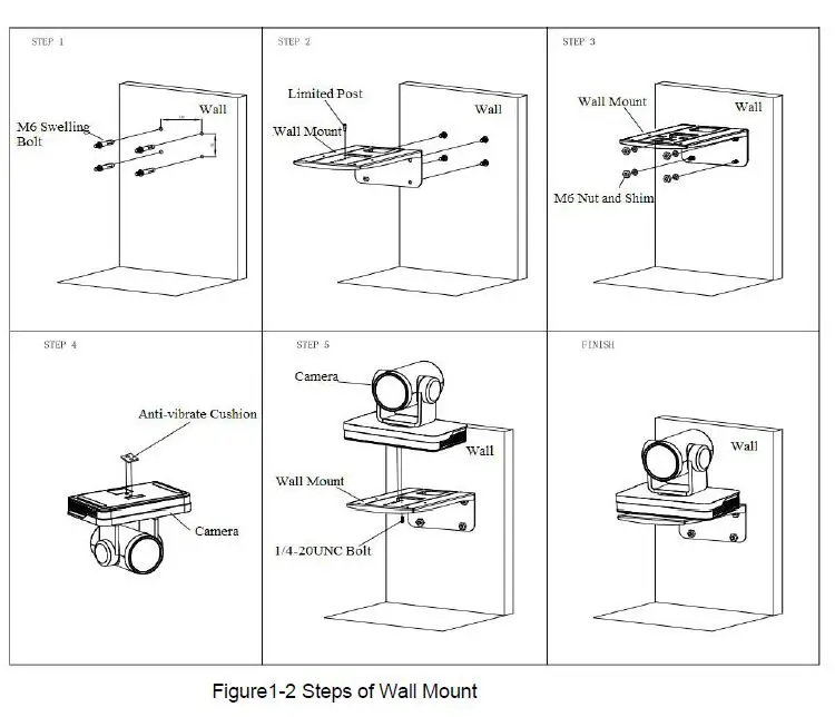
Bracket
Bracket can only be wall mounted or upside down mounted on template and concrete wall, but can not be installed on plasterboard.
Steps of Wall Mount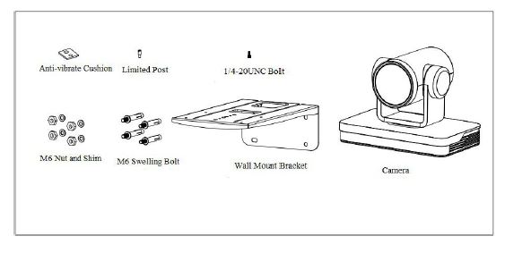
Steps of Ceiling Mount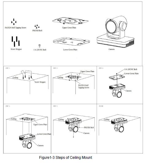
Product Overview
Product Dimension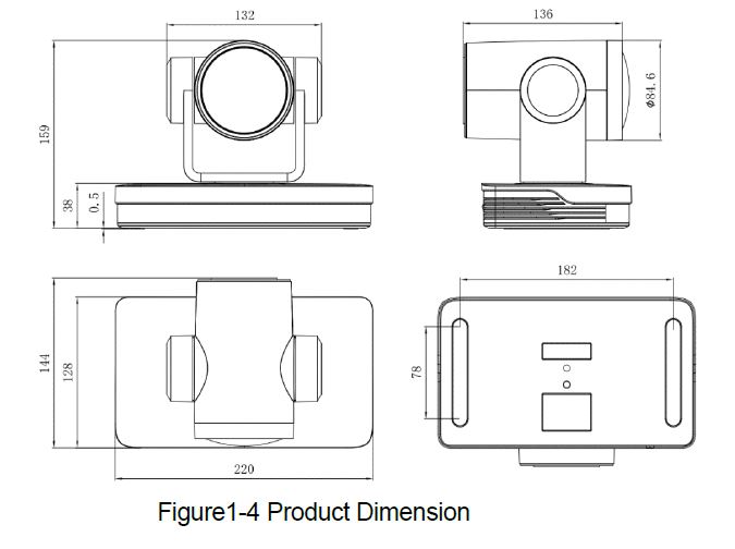
Accessory
When you unpack your package, check that all the supplied accessories are included
|
Supplied |
Power adapter |
| USB2.0 Cable | |
| User manual | |
| Plastic pad | |
|
Optional |
Wireless remote control |
| IR Remote Control | |
| Brackets for wall mounting | |
| Brackets for ceiling mount |
Product Feature
This is a brand new UHD 4K camera, including 3 lenses, 12X optical zoom 80.4°wide-angle lens, 25X optical zoom 59.2°wide-angle lens, and 31X optical zoom 59° wide-angle lens. It has complete functions, excellent performance and rich interfaces. Boasting advanced ISP processing technology and algorithm, cameras deliver the vivid image and uniform picture brightness.
- 4K UHD Resolution: SONY CMOS sensor. Resolution is up to 4K with frame rate up to 60fps.
- Dual Stream Output: USB support the main stream and sub stream output at the same time, and can meet the needs of near-end and far-end.
- Optical Zoom Lens: 12X optical zoom 80.4°wide-angle lens, 25X optical zoom 59.2°wide-angle lens, and 31X optical zoom 59° wide-angle lens
- Interfaces: Support HDMI, SDI, USB 2.0, LAN, and HDMI, USB, LAN output 4K audio and video at the same time.
- Leading Auto Focus Technology: Fast, accurate and stable auto focusing technology.
- Low Noise and High SNR: Super high SNR image is achieved with low noise CMOS. Advanced 3D noise reduction technology further reduces the noise while ensuring high image clarity.
- Multiple Audio/Video Compression Standards: LAN interface supports H.264/H.265 video compression, USB2.0 interface supports MJPG, H264, YUY2, NV12, H265; A-IN interface supports AAC audio compression coding
- Audio Input Interface: 8000, 16000, 32000, 44100, 48000 sampling frequency. support AAC audio compression
- Multiple Network Protocol: Support ONVIF, GB/T28181, RTSP, RTMP protocols; Support RTMP push mode, easy to be connected to streaming server (Wowza, FMS); Support RTP multicast mode; Support network full command VISCA control protocol.
- Control Interface: RS422 input(compatible with RS485), RS232 input/output, RS232 (cascade connection)
- Multiple Control Protocol: Support VISCA, PELCO-D, PELCO-P protocols; Support automatic identification protocols.
- Multiple Presets: Up to 255 presets (10 presets via remote control).
- AI Human Detection: Built in high speed processor and advanced image processing and analysis algorithm, and real-time tracking and zone tracking modes are available.
- Multiple Application: Online-education, Lecture Capture, Webcasting, Videoconferencing, Tele-medicine, Unified Communication, Emergency command andcontrol systems, etc.
Technical Specification
| Camera Parameter | ||||
| Optical Zoom | 12X | 25X | 31X | |
|
Focal Length |
f=3.85 mm~
46.2 mm ±5% |
f=7.1 mm~ 177.5
mm ±5% |
f=6.91 mm~ 214.21
mm ±5% |
|
|
Viewing Angle |
Horizontal:
7.59˚(N)~ 80.4˚(W) Vertical: 4.6˚(N)~ 50.0˚(W) |
Horizontal:
2.5˚(N)~ 59.2˚ (W) Vertical: 1.4˚(N)~ 34.6˚ (W) |
Horizontal:
1.98˚(N)~ 59˚ (W) Vertical: 1.12˚(N)~ 34.14˚ (W) |
|
|
Iris Value |
F1.8 ~
F3.56±5% |
F1.61 ~ F5.19±5% | F1.35 ~ F4.6±5% | |
|
Image Sensor |
1/2.5 inch SONY CMOS sensor |
1/1.8 inch SONY CMOS sensor |
||
| Effective Pixels | 8.29M megapixel 16:9 | |||
|
Video Formate |
HDMI:
3840*2160P60/50/25/59.94/29.97;1080P60/50/ 30/25/59.94/29.97;1080I60/50/59.94; 720P60/50/59.94; SDI: 1080P60/50/30/25/59.94/29.97;1080I60/50/59.94; 720P60/50/59.94 USB2.0: |
|||
| MJPG:3840*2160/1920*1080/1280*720
/1024*768 /1024*576/800*600/720*576/720*480/704*576/640*4 80 /640*360 /352*288/320*240P30; H264:3840*2160/1920*1080/1280*720 /1024*768 /1024*576/800*600/720*576/720*480/704*576/640*4 80 /640*360 /352*288/320*240P30; H265:1920*1080/1280*720 /1024*768 /1024*576/800*600/720*576/720*480/704*576/640*4 80 /640*360 /352*288/320*240P30; YUY2:800*448 /720*480P25; 640*360 /432*240P30 NV12:800*448P25; 640*480 /640*360 /432*240P30 |
|
| Minimum Illumination |
0.05Lux(F1.8, AGC ON) |
| DNR | 3D DNR |
| White Balance | Auto / Manual/ One Push/ Specified Temperature |
| Focus | Auto/Manual/One Push Focus |
| Exposure Mode | Auto/Manual/Shutter priority/Aperture priority/brightness priority |
| Aperture | F1.8 ~ F11, CLOSE |
| Shutter Speed | 1/25~1/10000 |
| BLC | ON/OFF |
| WDR | OFF/ Dynamic level adjustment |
| Video Adjustment |
Brightness, Color, Saturation, Contrast, Sharpness, B/W mode, |
| SNR | ≥50dB |
| AI Function | ||
| Real-time Tracking Mode | The longest tracking distance can reach 6-7 meters, which can support the speaker to walk at a speed of 5-6 mph | |
| Zone Tracking | 4 tracking zones are available, which can be set within -110°~ | |
| Mode | +110°in horizontal and 30°~+30° in vertical. |
| Interface Parameter | |||
|
Video Interfaces |
HDMI, SDI, LAN(Support POE), USB2.0, A-IN, RS232-IN,
RS232-OUT, RS422(Compatible with RS 485), Rotary DIP switch, DC12V Power Supply, Power Switch |
||
| Video Compression
Format |
LAN:H.264, H.265
USB 2.0:MJPG, H264, H.265, YUY2, NV12 |
||
| Audio Input | Double track 3.5mm linear input; | ||
| Audio Output | HDMI, LAN, USB2.0, SDI | ||
| Audio Compression
Format |
AAC |
||
|
LAN Jack |
10M/100M/1000M adaptive Ethernet port, support POE power supply, support audio and video output | ||
| Network Protocols | RTSP/RTMP,ONVIF,GBT28181 Support network VISCA control protocol; Support remote upgrade, remote restart, remote reset | ||
| Control Jacks | RS232-IN,RS232-OUT, RS422 compatible with RS485 | ||
| Serial Port
Communication Protocols |
VISCA/Pelco-D/Pelco-P;
Support Baudrate: 115200/38400/9600/4800/2400 |
||
| USB
Communication Protocol |
UVC ( Video Communication Protocol ) , UAC ( Audio Communication Protocol) | ||
| Power Supply | HEC3800 Outlet (DC12V) | ||
| Power Adapter | AC110V~AC220V to DC12V/2.5A | ||
| Input Voltage | DC12V±10% | ||
| Input | <1A | ||
| Consumption | <12W |
| PTZ Parameter | |
| Pan Move | -110°~+110° |
| Tilt Move | -30°~+30° ° |
| Pan Speed | 0.1°/s~100°/s |
| Tilt Speed | 0.1°/s~70°/s |
| Preset Speed | Pan: 78.8°/s, Tilt: 31.7°/s |
| Preset Quantity | Up to 255 preset (10 via remote control) |
| Other Parameter | |
| Storage Temperature | -10℃~+60℃ |
| Storage Humidity | 20%~95% |
| Working Temperature | -10℃~+50℃ |
| Working Humidity | 20%~80% |
| Dimension | 220(L)mm*144mm(W)*159mm(H) |
| Weight | 1.7kg |
| Environment | Indoors |
| Accessory | |
| Supplied Accessory | Power Supply, RS232 Control Cable, USB2.0 Cable(U3 model), IR Remote Control, User Manual, Warranty Card |
| Optional Accessory |
Ceiling / Wall Mount (Extra Cost) |
Interface Introduction
Interface Diagram
The external interfaces of this product include: HDMI interface, USB2.0 interface, SDI interface, and audio input interface, network interface, RS232 input/output, RS422/RS485 interface, DC12V power supply, interface power switch. The external interface diagram is shown in Figure 2.5:
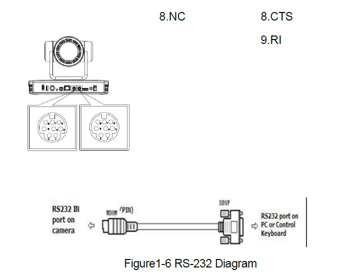
RS-232
RS-232 Mini-DIN 8-pin Terminal Port Definition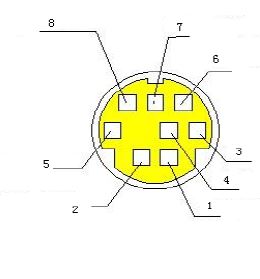
|
NO. |
Terminal Port |
Definition |
| 1 | DTR | Data Terminal Ready |
| 2 | DSR | Data Set Ready |
| 3 | TXD | Transmit Data |
| 4 | GND | System Ground |
| 5 | RXD | Receive Data |
| 6 | GND | System Ground |
| 7 | IR OUT | IR Commander Signal IR |
| 8 | NC | No Connection |
RS232(DB9) Terminal Port Definition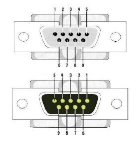
|
NO. |
Terminal Port | Definition |
|
NO. |
Terminal Port | Definition |
| 1 | DCD | Data Carrier Detect |
| 2 | RXD | Receive Data |
| 3 | TXD | Transmit Data |
| 4 | DTR | Data Terminal Ready |
| 5 | GND | System Ground |
| 6 | DSR | Data Set Ready |
| 7 | RTS | Request to Send |
| 8 | CTS | Clear to Send |
VISCA Networking Method
This camera has RS232 Input/Output interface, you can cascade as above method
Rotary Dial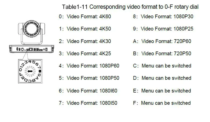
How to Use
Video Output
Power-on Self-test
After powering on, camera will have initial configuration and receiver light will be flashing. Camera will do a brief pan-tilt tour and return to the home position, or if preset 0 is set, the camera will return to the preset 0 position).
Video Output
- Network output: connect this product and your computer through network cable, then open the browser, enter the camera IP address (factory default 192.168.5.163) in the address bar, then to the login page and input a user name and password (factory default are “admin”) ,Finally enter the preview page, and the image comes out.
- If you forget your user name, password, IP address, you can manually restore the default by the remote controller key combination * #
- SDI, HDMI Output: Connect the monitor with the corresponding video output interface.
- USB2.0 Output: Connect this product with computer USB2.0 interface, open the Device Manager to see whether there is an image device and whether the Universal Serial Bus controllers recognize USB2.0 device. After properly identified, open the software, choose the image device and then it will output image.
Remote Control
Remote control using instruction: There are wireless remote control and IR remote control for options. Steps for wireless remote control usage are as below:
Code Pairing
- Press the “Settings” + “*” button for 3 seconds, the LED will turn off to flashing, after releasing the button, the LED light will keep flashing to start the code pairing, the receiver is powered on, and the LED will be off when the code pairing is successful; If you use other remote control, you need to clear the code of this remote control, or re-pair the code of the new remote control. If the code pairing has been unsuccessful, the red LED light flashes for 20 seconds and then goes out, stop the code pairing and go to sleep; at this time, press any key to wake up and re-pair the code.
- After the code is successfully matched, you need to select the camera address to control it
- Clear Code Data
Press the “Settings” key + “#” key from light off to flashing, the receiving end is powered off and then powered on. The LED is off, indicating that the paired data is cleared successfully - Enter Sleep Mode and Wake Up
If there is no operation in the working state, it will immediately enter the sleep mode, and press any key to wake up.
IR Remote Control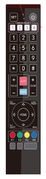
- Standby Key
After 3S long press, the camera will step into standby mode. Long press 3S again, the camera will self-test again and back to HOME position. (Note: If power-on mode is turned on and Preset 0 is set, and there is no operation within 12s, it will automatically point to the specified preset position. - Camera Address Selection
Select the camera address which wants to be controlled - Number Key
Set or run 0-9 presets - Key
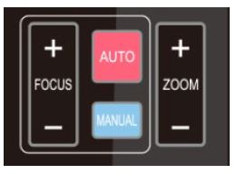
Key combination use - Focus Control Key
Auto Focus: Enter into auto focus mode.
Manual Focus: The camera focus mode is manual
Switch the camera focus mode to manual focus by pressing [focus +] or [focus -] to adjust - Zoom Control Key
Zoom+:Lens near
Zoom-:Lens far - Set or Clear Preset key:
Set Preset: Set preset key + 0-9 number key:
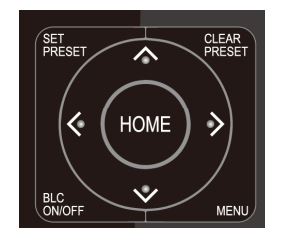
Clear Preset key: Clear preset key + 0-9 number key - Pan/Tilt Control Key
Press Key :Up
Press Key :Down
Press Key :Left
Press Key: Right
“HOME” Key: Return to the middle position or enter into the next level menu - BLC Control Key
Back Light ON / OFF: Turn on or off the back light - Menu Setting
Open or close the OSD menu
Enter / exit the OSD menu or return to the previous menu. - Camera IR Remote Control Address Setting
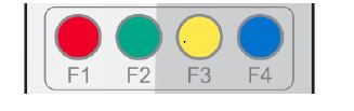
【*】+【#】+【F1】:Camera Address No.1
【*】+【#】+【F2】:Camera Address No. 2
【*】+【#】+【F3】:Camera Address No. 3
【*】+【#】+【F4】:Camera Address No. 4 - Key Combination Functions

- AI Function Short Keys
Remote Control Usage
Finishing initialization, it can receive and execute the IR commands. Press the remote controller button, the indicator light is flashing; release the button, the indicator light stops flashing. Users can control the pan/tilt/zoom, setting and running preset positions via the IR remote controller.
Key Instruction:
- In this instruction, “press the key” means a click rather than a long-press, and a special note will be given if a long-press for more than one second is required.
- When a key-combination is required, do it in sequence. For example,“ 【 *】+【#】+【F1】”means press“【*】”first and then press“【#】” and last press“【F1】”
- Camera Selection

- Pan/Tilt Control
- Up: press Down: press
- Left: press Right: press
- Back to middle position: press“【HOME】”
- Press and hold the up/down/left/right key, the pan/tilt will keep running, from slow to fast, until it runs to the endpoint; the pan/tilt running stops as soon as the key is released
- Zoom Control
- ZOOM IN: press “ZOOM “ key
- ZOOM OUT: press “ZOOM ” key
- Press and hold the key, the camera will keep zooming in or zooming out and stops as soon as the key is released
- Focus Control
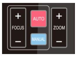
- Focus (near):Press “【focus+】” key (Valid only in manual focus mode)
- Focus (far): Press “【focus-】”key (Valid only in manual focus mode)
- Auto Focus: Support
- Manual Focus: Support
- Press and hold the key, the action of focus will keep continue and stops as soon as the key is released.
- BLC Setting

- BLC ON / OFF: support
- Presets Setting, Running, Clearing
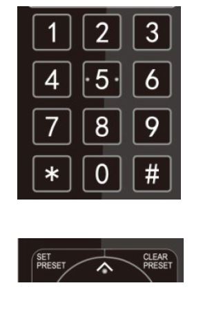
- Preset setting: to set a preset position, the users should press the “【SET PRESET】” key first and then press the number key 0-9 to set a relative preset,
Note: 10 preset positions in total are available by remote controller. - Preset Running: Press a number key 0-9 directly to run a relative preset.
Note: Action in vain if a relative preset position is not existed. - Preset clearing : to clear a preset position, the user can press the “【CLEAR PRESET】” key first and then press the number key 0-9 to clear the relative preset;
Note : press the“【#】” key three times continually to cancel all the presets.
- Preset setting: to set a preset position, the users should press the “【SET PRESET】” key first and then press the number key 0-9 to set a relative preset,
- Camera Remote Controller Address Setting
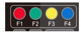
- 【*】+【#】+【F1】:Camera Address No.1
- 【*】+【#】+【F2】:Camera Address No. 2
- 【*】+【#】+【F3】:Camera Address No. 3
- 【*】+【#】+【F4】:Camera Address No. 4
- Camera Selection
Menu Setting
Main Menu
In normal working mode, press 【MENU】key to display the menu, using scroll arrow to point at or highlight the selected items.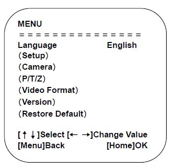
System Setting
Move the pointer to the (Setup) in the Main Menu, click the【HOME】key and enter into the (System Setting) as shown below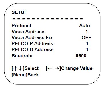
- PROTOCOL: VISCA/Pelco-/Pelco-D/Auto
- Visca ADDR: VISCA=1~7 Pelco-P=1~255 Pelco-D = 1~255
- Visca Address Fix: On/Off
Camera Parameter Setting
Move the pointer to the (CAMERA) in the Main Menu, click the【HOME】key and enter the (CAMERA) as follow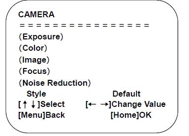
- Exposure: Enter into Exposure setting
- Color: Enter into color setting
- Image: Enter into image setting
- Focus: Enter into focus setting
- Noise Reduction: Enter into noise reduction
- Style: Default, standard, clear, bright, soft
Exposure
Move the pointer to the (EXPOSURE) in the Main Menu, click the【HOME】and enter the (EXPOSURE SET) as follow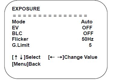
- Mode : Auto, Manual, Shutter priority, Iris priority and Brightness priority.
- EV : On/Off (only available in auto mode)
- Compensation Level: -7~7 (only available in auto mode when EV is ON)
- BLC: ON/OFF for options (only available in auto mode)
- Anti-Flicker: OFF/50Hz/60Hz for options (only available in Auto/Iris priority/Brightness priority modes)
- Gain Limit: 0~36(only available in Auto/ Iris priority /Brightness priority mode)
- Shutter: 1/30, 1/60, 1/90, 1/100, 1/125, 1/180, 1/250, 1/350, 1/500, 1/725, 1/1000, 1/1500, 1/2000, 1/3000, 1/4000, 1/6000, 1/10000 (only available in Manual and Shutter priority mode)
- IRIS :OFF,F11.0,F9.6,F8.0,F6.8,F5.6,F4.8,F4.0,F3.4,F2.8,F2.4,F2.0,F1.8(only available in Manual and Iris priority mode)
- Brightness: 0~14 (only available in Brightness priority mode)
Color
Move the pointer to the (COLOR) in the Main Menu, click the【HOME】and enter the (COLOR SET) as follow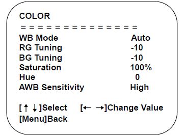
- WBMode: Auto, Manual, One Push, 3000K/3500K/4000K/4500K/5000K/5500K/6000K/6500K/70000K.
- Red Tuning: -10~10(only available in Manual mode)
- Blue Tuning: -10~10(only available in Manual mode)
- Red Gain: 0~255(only available in Manual mode)
- Blue Gain: 0~255(only available in Manual mode)
- Saturation: 60%, 70%, 80%, 90%, 100%, 110%, 120%, 130%, 140%, 150%, 160%, 170%, 180%, 190%, 200%
- Hue: -15~15 AWB Sensitivity: high/middle/low (only available in Auto mode)
IMAGE
Move the pointer to the (IMAGE) in the Menu, click the【HOME】and enter the (IMAGE) as follow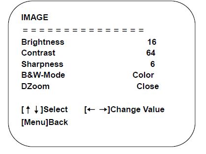
- Brightness: 0~32
- Contrast: 0~128
- Sharpness: 0~11
- B&W Mode: Color, black/white
- DZoom: Digital zoom options: On/Off
Focus
Move the pointer to the (FOCUS) in the Menu, click the【HOME】and enter the (FOCUS) as follow.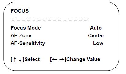
- Focus Mode: Auto, manual
- AF-Zone: Up/middle/down
- AF-Sensitivity: High, middle, low
Noise Reduction
Move the pointer to the (NOISE REDUCTION) in the Menu, click the【HOME】and enter the (NOISE REDUCTION) as follow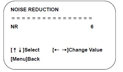
- Noise Reduction: Close, 1~11
P/T/Z
Move the pointer to the (P/T/Z) in the Main Menu, click the【HOME】and enter the (P/T/Z) as follow.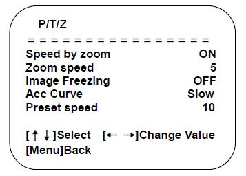
- Depth of Field: Only effective for remote controller, On/ Off;
- When zoom in, the Pan/Tilt control speed by remoter will become slow
- Zoom Speed: Set the zoom speed for remote controller,1~8
- Image Freezing: On/Off
- Accelerating Curve: Fast/slow
- Preset Speed: 1-10
Video Format
Move the pointer to the (Video Format) in the Menu, click the【HOME】and enter the (Video Format) as follow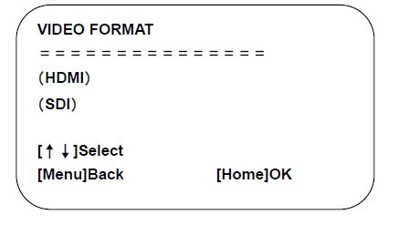
- HDMI: Enter HDMI sub-menu item
- SDI: Enter the SDI submenu item
Exit menu after modifying parameter to save it
HDMI
Move the pointer to the (Video Format) in the Menu, click the【HOME】and enter the HDMI (Video Format) as follow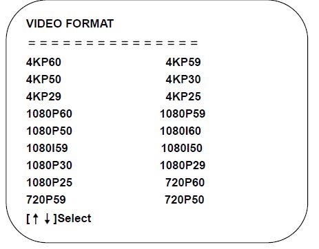
HDMI: 4KP60、4KP59、4KP50、4KP30、4KP29、4KP25、1080P60、1080P59、1080P50、1080I60、1080I59、1080I50、1080P30、1080P29、1080P25、720P60、720P59、720P50
SDI
Move the pointer to the (Video Format) in the Menu, click the【HOME】and enter the SDI (Video Format) as follow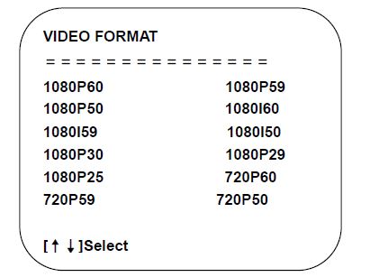
SDI: 1080P60、1080P59、1080P50、1080I60、1080I59、1080I50、1080P30、1080P29、1080P25、720P60、720P59、720P50
Version
Move the pointer to the (VERSION) in the Main Menu, click the【HOME】and enter the (VERSION) as follow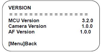
- MCU Version: Display MCU version information
- Camera Version: Display camera version information
- AF Version: Display the focus version information
Restore Default
Move the pointer to the (VERSION) in the Main Menu, click the【HOME】and enter the (VERSION) as follow.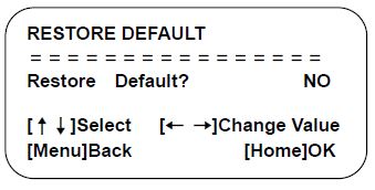
Restore default:
Yes/No ;( after restoring default, the language, color, and video format won’t be restored)
If the address of former remoter is not 1 but another one from 2,3,4,the corresponding camera address will restore to 1 when all parameters or system parameters are restored. User should change the remoter address to be 1 (press No.1 according to the camera so to get normal operation)
NETWORK CONNECTION
Connection Method
- Direct Connection:Direct connections via “cross-over” network cable
- Connection to LAN:Connections to LAN via patch cable to LAN wall jack or LAN switch
- Please do not put the power and network cable in places where can be easily touched to prevent video quality lowered by unstable signal transmission due to poor contact of cables.
The computer must have the network segment where the camera IP address belongs to. The device will not be accessible if without the segment. I.E. The camera default IP address is 192.168.5.163, then segment 5 must be added in the computer. Specific steps are as below:
Firstly open the window of Local Area Connection Properties on computer, select the “Internet protocol version 4(TCP/IPv4)” as shown by picture on the left. Double click or click the property “Internet” protocol version 4 (TCP/IPv4)to enter into the Internet Protocol Version 4(TCP/IPv4) Properties window, select “Advanced” to enter into the Advanced TCP/IP Setting and add IP and subnet mask in the IP browser as picture shown below. Click the “Confirm” to finish the adding of IP segment. User can add the corresponding network segment according to the revised IP address of the camera. - The IP address to be added cannot be same with that of other computers or devices. The existence of this IP address needs to be verified before adding.
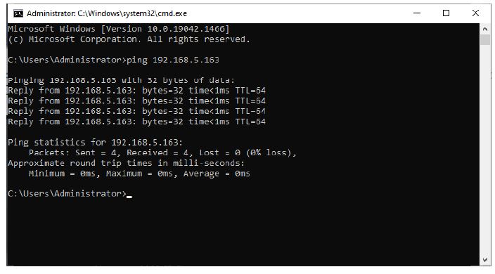
Click the “Start” and select “Operation” to input cmd as picture below to verify if the network segment has been successfully added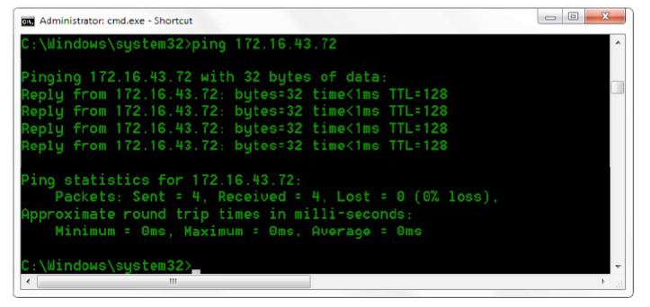
- User can also to verify network connection as steps above mentioned after the finish of camera self-check. If IP is default, open DOS command window and input 192.168.5.163, then press Enter key. It will show message as below: which means network connection is normal.
Camera Web Interface
Web Login
After assigning an IP address to the camera, you can reach the Web Interface by typing in the camera’s IP address into a web browser. You can log in this interface as administrator or user. If as administrator, type in “admin” into the username and password fields. If as user, type in “user1” or “user2” into the username and password fields. From the Web Interface, you can control the camera using the arrows on the left side. You can also adjust many of your camera’s settings via this IP interface.
Note:
- If login as “user”, your rights are limited to preview, playback, and logout (No configuration right)
- Browsers that support Web function are Google, IE, 360 and other popular browsers.
Language Selection: On the right top of the interface display “中文|English”, click “English”. - Download Plug-in
When first using IE browser to access the web conferencing camera, the login page will appear “Playback plug-in is not installed, please download and install!” Click on this message, download and install MRWebXinstall.exe, according to information prompts.
After installing the plugin, enter user name and password, click and Sign (initial default user name and password: “admin”, users can change the user name and password on their own after entering) into the Web client management interface.
Preview
After successful login into the management interface, it enters the video preview interface. In the preview screen, users can control PTZ, zoom, focus, video capture, sound, focus, full screen and set the preset position, run, delete and other operations.
You can record the video and save it on SD Card when SD Card built in. Video can be saved on the Computer at Local.
- Login as administrator
User name and default password: admin
You can control PTZ, zoom, focus, video capture, sound, focus, full screen and set run, and delete the preset position. - Login as user
User name and default password: “user1” or “user2”
You can control PTZ, zoom, focus, video capture, sound, focus, full screen and set run, and delete the preset position
Monocular AI Tracking Function Web Page Configuration
- After login, enter into the management interface and turn on Tracking below “Monocular Tracking”
- On the right top is PTZ control area, in which you can set the preset region of Regional Tracking. Interface is as below.
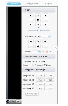
Regional Settings Steps (We take Region1 as an example):
- On the PTZ Area, adjust image by clicking direction buttons to select one region.
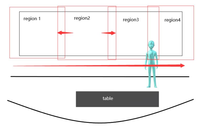
- After finishing region1 setting, click “Set” to complete the Region1 Tracking. Other region settings are same as region1 setting steps.
You can set 4 different regions, and minimum 2 regions. And the Regional Tracking settings can only be configured through the webpage.
Call out the regional tracking: Click “Run” of corresponding region on the “Regional settings” area.
Configuration
Click Configuration to enter into the device parameters setting page
There are the following options: Local configuration, audio configuration, video configuration, network configuration, internet access configuration, system configuration, detailed description see the following table.
| Menu | Explanation |
| Audio Configuration | Including audio compressing format, sampling frequency, sampling precision, compressing code rate settings etc. |
| Video Configuration | Including video encoding, video parameters, character-overlapping, character size, video output setting etc. |
| Network Configuration | Including basic parameters, Ethernet, DNS, wireless network setting, GB28181 etc. |
| System Configuration | Including equipment property, system time, user management, version update, Reset, Reboot device settings etc. |
Explanation of Camera Configuration
Audio Configuration
- Switch: Choose to enable the audio or not.
- Compressing Format: Set audio compressing format and manually reboot the device after change (default PCM,AAC optional)
- Sampling Frequency: Set sampling frequency and manually reboot the device after change (AAC default 16000, 32000, 44100, 48000 optional,
- Sampling Precision: Set sampling precision (default 16bits)
- Compressing Code Rate: Set audio compressing code rate (default 64bits, 32, 48, 96,128bits optional)
- Channel Type: Set the channel type (mono by default, stereo optional)
- Input volume: set the input volume (default 2,1-10 optional)
Note Click “SAVE”, it will display “Successfully saved. Restart the device to take effect”.
Video Configuration
Video Encoding
- Code Stream: Different video output mode setting, use different streams. (Main stream, secondary stream)
- Compression Format: Set the video compression format, save to take it effect (primary/secondary stream default:H.264,H.265 optional)
- Profile: Profile Mode Setting (Default HP,BP,MP Optional)
- Video Size: Set video image resolution, save to take it effect (main stream default 1920 * 1080 or 1280 * 720 optional; default secondary stream 640 * 320,320 * 180,1280 * 720,1920 * 1080 optional )
- Stream Rate Control: Set rate control mode, save to take it effect (Primary / secondary stream default variable bit rate, fixed rate is for option).
- Image Quality: Set the image quality, image quality can be changed only when rate control is variable bit rate,(main stream defaulted is better, secondary stream default is not good, there are best, better, good, bad, worse, worst for options).
- Rate (Kb / s): Set the video bit rate (main stream default 4096Kb / s,64-12288Kb / s optional; secondary stream default 1024Kb / s,64-10240Kb / s optional).
- Frame rate (F / S): Set the video frame rate (primary / secondary stream default 25F / S, primary stream 5-60F/S optional, secondary stream 5-30F / S optional ).
- Key frame interval: Set the key frame interval (primary/secondary stream default 75F,primary / stream 1-300F optional. secondary stream 1-150F optional).
- Minimum QP of key frame interval: Set minimum QP of key frame interval(Default 20, 10-51 optional)
- Stream Name: When streaming via rtsp or rtmp, user can modify stream name. Main Stream(live/av0), sub stream(live/av1)
- Click the “Save” button to display the “Parameter saved successfully” message, then settings take effect.
Stream Release
- Switch: To turn on/off the main / secondary stream.
- Protocol: primary / secondary stream applies RTMP protocol.
- Host Port: server port number (default 1935,0-65535 optional)
- Host Address: server IP addresses (default 192.168.5.11)
- Stream Name: choose a different stream name (live / av0,live / av1 optional).
- User: Set the user name.
- Password: Set the password.
- Click on the “Save” button to display the “Save successful” message,then settings take effect.
RTP Broadcasting
- Main/Sub Stream:On/off;
- Protocol:RTP or TS
- Address:Default 224.1.2.3. It can be edited.
- Port:The main stream defaults to 4000, the secondary stream defaults to 4002, and the main/secondary stream is optional from 0 to 65535.
- Visit:Address comes up after setting. Eg; rtp://224.1.2.3:4000;udp://@224.1.2.3:4000;tcp://@224.1.2.3:4002;
Video Parameters
- Focus: Focus mode, focus tactic, focus sensitivity can be set.
- Focus Mode: set the focus mode (Default automatic, manual optional, one-push)
- Focus Tactic: set the focus tactic (Default before-focus, after-focus, normal meeting, education tracking, moving-target focus, center focus optional.)
- Focus Sensitivity: Set the focus sensitivity (default is low, high, medium optional)
- Exposure: Exposure mode, exposure compensation, backlight compensation, anti-flicker, gain limit, shutter, aperture, brightness, gain can be set.
- Exposure Mode: Set the exposure mode (Default automatic, manual, shutter priority, aperture priority, brightness priority optional)
- Exposure Compensation: Exposure compensation setting is active when it is auto status (default is off).
- Exposure Compensation Value: Set the exposure compensation value, valid when Exposure Compensation is on (default 0,-7 to 7 optional).
- BLC: Set back light compensation, valid when it is auto status (default is off).
- Gain Limit: Set the gain limits, valid in auto focus, iris priority, and brightness priority.
- Gain: Set gain, only valid in manual exposure mode and shutter priority (default 0, 0~20 optional)
- Shutter Speed: Set shutter speed value, valid in manual focus and shutter priority. (default 1/100,1/25,1/30,1/50,1/60,1/90,1/100,1/120,1/180,1/250,1/350,1/500,1/1000,1/2000,1/3000,1/4000,1/6000,1/10000 optional).
- Aperture Value: Set the aperture value, valid in auto focus and iris priority (default F1.8,closed, F11, F9.6,F8.0,F6.8,F5.6,F4.8,F4.0,F3.4,F2 .8,F2.4,F2.0,F1.8 optional).
- Brightness: Set the brightness value, valid in brightness priority mode (default 7,0-23 optional).
- Color: White balance, saturation, hue, white balance sensitivity, red fine tuning, blue fine tuning, red gain, blue gain can be set.
- White Balance Mode: Set the white balance mode (Default automatic, manual, one-push white balance, 3000K, 3500K, 4000K, 4500K, 5000K, 5500K, 6000K, 6500K, 7000K optional).Note: Right click the “Correction” button when selected the One-push white balance mode.
- Saturation: Set the saturation (default 100%,60%, 70%, 80%, 90%, 100%, 110%, 120%, 130%, 140%, 150%, 160%, 170%, 180%, 190%, 200% optional).
- Red Fine Tuning: Set red fine tuning, valid in manual white balance mode.
- Blue Fine Tuning: Set Blue fine tuning, valid in manual white balance mode.
- Chroma: Set the chrome (default 7, 0-14 optional).
- Auto White Balance Sensitivity: Sensitivity Auto white balance settings (default is low, high, medium optional).
- Red Gain: Set the red gain, effective when it is manual (default 145, 0-255 optional).
- Blue Gain: Sets the Blue gain, effective when it is manual (default 56, 0-255 optional).
- Image: You can set brightness, contrast, sharpness, gamma curve, dynamic contrast, black and white mode, horizontal flip, vertical flip, electronic zoom, ultra-low illumination
- Brightness: Set the brightness (default 7, 0-14 optional).
- Contrast: Set the contrast (default 7, 0-14 optional).
- Sharpness: Set the sharpness value (default 6, 0-15 optional).
- Gamma: Gamma value setting (default 0.45, 0.50, 0.55, 0.63 optional).
- Dynamic Contrast: Set dynamic contrast (default off, 1-8 optional)
- BW Mode: Set black and white mode (default color, black/white optional ).
- Digital Zoom: Set digital zoom (default off, on optional)
- Lens Distortion Calibration: Set image distortion (default off, on optional)
- Noise Reduction: 3D noise reduction and dynamic dead pixel correction available.
- 3D Noise Reduction: Set 3D noise reduction level (default 3, 1-8 and off optional).
- Dynamic dead pixel correction: Set Dynamic dead pixel correction (default 4, 1-5 optional).
- Style: Select image (Default, standard, brightness, clarity, and soft can be set)
Refresh the page after changing above parameters in a, b, c, d, e, f to take effect.
Character Overlapping
- Display Time & Date: Yes/No
- Display Title: Yes/No
- Time, Font and Color: Default white, black, yellow, red and blue optional)
- Title Font Color: Default white, black, yellow, red, and blue optional)
- Move Character: Set the location where the time and title to display. Click “ up, down, left, right” button to move the characters’ location.
- Title: Set title on device property (default CAMERA1)
- Time: Set time on system time (default 1970/01/01 05:36:00)
- Click “Save” button, “parameters are successfully saves” window pop-up, which means the setting take effect.
Character Size
- Automatically Adjust According to the Resolution: Yes/No
- Main Stream Character Size: Set the character size of the display, the device will automatically restart after changed (default 48, 28-200 optional)
- Secondary Stream Character Size: Set the character size of the display, the device will automatically restart after changed (default 48, 28-200 optional)
- Click “Save” button, “parameters are successfully saves” window pop-up, which means the setting take effect.
Video Output
- Output Format: Set the video output format
- Click “Save” button, “parameters are successfully saves” window pop-up, which means the setting take effect
Network Configuration
Network Port
- Data Port: set the data port, the device will restart automatically after changed (default 3000,0-65535 optional).
- Web Port: Set Web port, the device will restart automatically after changed (default is 80, 0-65535 is optional).
- Onvif Port: Set Onvif port, the device will restart automatically after changed (default 2000, 0-65535 optional).
- Soap Port: Set Soap port (default 1936, 0-65535 optional).
- RTMP Port: Set RTMP port (default 1935, 0-65535 optional).
- RTSP Port: Set RTSP port, the device will restart automatically after changed (default 554,0-65535 optional).
- Visca Port: Set Visca port, the device will restart automatically after changed (default 3001,0-65535 optional).
- Https Port: Set http port, the device will restart automatically after changed (default 443, 0-65535 optional).
- WebSocket Port:Set WebSocket port, the device will restart automatically after changed (default 8088, 0-65535 optional).
- Click on the “Save” button, it will be valid when display “Save successful
- RTMP access: RTMP: / / equipment IP address: 1935 / live/av0 (av0 main stream; av1 second stream)
- RTMP Access:Rtmp://equipment IP address: 1935 / live/av0 (av0 main stream; av1 second stream)
Ethernet Parameter
- DHCP: Enable or disable obtain IP automatically can be set. After saved, reboot the device to takes effect (default: OFF)
- IP Address: Set the IP address, after saved, reboot the device to takes effect (default 192.168.5.163).
Note: This IP address is the same with the one used to login Web page. - Subnet Mask: Set the subnet mask (default 255.255.255.0).
- Default Gateway: Set the default gateway (default 0.0.0.0).
- Physical Address: Set the physical address (the parameter is read-only)
- Click the “Save” button, it will be valid when display “Save successful”. (Note: To prevent IP conflicts when modify).
DNS parameters
- Preferred DNS Server: Set the preferred DNS server. (Default 0.0.0.0).
- Alternate DNS Server: Set alternate DNS server. (Default 0.0.0.0).
- Click the “Save” button, it will be valid when display “Save successful”.
GB28181
- Switch: Set whether to activate GB28181.
- Time Synchronization: Enable/Disable time synchronization
- Stream Type: Set stream type (default main stream, secondary stream optional)
- Signing Time (in seconds): 3600, range 5-65535
- Heartbeat Time (seconds): 60, range 1-65535
- Register ID: 34020000001320000001
- Register User Name: IPC
- Register Password: 12345678
- Equipment Ownership: Users can add their own
- Administrative Regions: Users can add their own
- Alarm Zone: Users can add their own
- Equipment Installation Address: Users can add their own
- Local SIP Port: 5060 Range 0-65535
- GB28181 Server Address: IP address of the computer
- Server SIP Port: 5060 Range 0-65535
- Server ID: 34020000002000000001
- Click on the “Save” button, it will be valid when display “Save successful”.
SRT
- SRT Port: Set the SRT port (default 9000, 0-65535 optional)
- SRT Password: Set SRT password
- SRT Password Length: Set the SRT password length (default 0, 16, 24, 32 optional)
- Click the “Save” button, and the prompt message “Parameters saved successfully! It will take effect after restarting!”
RTMP
- Enable RTMP: Enable/Disable RTMP
- Click the “Save” button, and it will display “Parameters saved successfully! The new parameter will take effect after restarting.
RTSP
- Enable RTSP: Enable/Disable RTSP
- RTSP Authentication: Set RTSP authentication, default off, on optional
- Click the “Save” button, and the prompt message “Save successfully! Modify RTSP authentication parameters will take effect after restarting the device!” will be displayed. After setting, restart the camera to take effect.
System Configuration
Device Properties
- Device Name: Set the device name (Default Camera-1, user can add their own).
- Device ID: Set the device ID (default 1, read-only).
- System Language: Set the system language (default Simplified Chinese, English optional).Need to re-login after modify and save the setting.
- Click on the “Save” button, it will be valid when display “Save successful”.
System Time
- Date Format: Set the date format (YYYY-MM-DD default year – month – day, MM-DD-YYYY namely Month – Day – Year, DD-MM-YYYY date – month – year Optional).
- Date Separator: set the date separator (default ‘/’,’.’,’-‘ Optional).
- Time Zone: Set the time zone (default UTC+08:00, other time zones optional).
- Time Type: Set the time types (default 24 hours, optional 12 hours).
- Enable NTP: Enable/disable NTP
- Update Interval: Set the NTP server automatic updated time interval. Valid after setting NTP server synchronization (default one day, 2-10 days Optional).
- NTP Server Address or Domain Name: Set NTP server address or domain name (default time.nits.gov). Valid after setting NTP server synchronization.
- NTP Server Port: Sets the NTP server port (default 123).Valid after setting NTP server synchronization.
- Click on the “Save” button, it will be valid when display “Save successful”.
User Management
- Select Users: Set the user type (the default administrator, User 1, User 2 optional)
- User Name: Set the user name (Select User Administrator default admin; select a common user1 default user1; to select a common user 2 default user2; user can modify their own)
- Password: Set a password (Select User Administrator default admin; select a common user1 default user1; to select a common user 2 default user2; user can modify their own).
- Password Confirmation: Confirm the input passwords are the same or not.
Version Update
The version information displayed on the page is read-only version and cannot be modified by the user. It is the same as the version information in the menu. The version information of different device models is different.
Update File: Click “Browse…” in the pop-up window and select the upgrade file; click the “Upgrade” button, the upgrade dialog box will pop up. After successfully update, device will automatically reboot. (Note: Make sure that the device power and network can work during update, if not, the upgrade will fail.)
After the version upgrade is completed, you need to restore the factory default values
- restore the factory default through web configuration;
- restore the factory default value through the menu;
- remote control shortcut key *#6 restore factory default;
Choose one of the above three methods, in which the IP account and password of “method a” are also restored to the default.
Restore Factory Setting
Click “Restore Factory Defaults” button and choose “yes” or “no” on pop-up window, then the device will restart automatically and restore factory setting.
Reboot
Click “Reboot” button and choose “yes” or “no” on the pop-up window, then the device will restart automatically.
Logout
Click “Logout”; and select “Yes” or “No” on pop-up window. If choose “Yes”, you will exit the current page and return to the user login interface again.
Serial Port Communication Control
In normal working state, you can control the camera through RS232/RS485 (VISCA IN) cable. The parameter of RS232 is as below:
- Baud rate: 2400/4800/9600/115200/second
- Start Bit:1 bit;
- Data Bit:8 bit;
- Stop Bit:1 bit;
- Verification Bit:None.
After power on, the camera will have a brief tour and then back to the center position.
The zoom lens is pulled to the farthest position, and then pulled back, after that self-test is completed.
VISCA Protocol List
VISCA Protocol List
| Ack/Completion Message | ||
| Command packet | Remark | |
| ACK | z0 41 FF | Returned when the command is accepted. |
| Completion | z0 51 FF | Returned when the command has been executed. |
z = device address + 8
| Error Messages | ||
| Command packet | Remark | |
|
Syntax Error |
z0 60 02 FF |
Returned when the command format is different or when a command with illegal command parameters is accepted. |
|
Command Buffer Full |
z0 60 03 FF |
Indicates that two sockets are already being used(executing two commands) and the command could not be accepted when received. |
|
Command Canceled |
z0 6y 04 FF(y: Socket No.) |
Returned when a command which is being executed in a socket specified by the cancel command is canceled. The completion message for the command is not returned. |
|
No Socket |
z0 6y 05 FF(y: Socket No.) |
Returned when no command is executed in a socket specifild by the cancel command, or when an invalid socket number is specified. |
|
Command Not Executable |
z0 6y 41 FF(y:
Execution command Socket No. Inquiry command: 0) |
Returned when a command canot be executed due to current conditions.For example, when commands controlling the focus manually are received during auto focus. |
Camera Control Command
| Command | Function | Command Packet | Remark |
| AddressSet | Broadcast | 88 30 0p FF | p:Address setting |
| IF_Clear | Broadcast | 88 01 00 01 FF | I/F Clear |
| CAM
_Power |
On | 8x 01 04 00 02 FF |
Power ON/OFF |
| Off | 8x 01 04 00 03 FF | ||
|
CAM_Zoom |
Stop | 8x 01 04 07 00 FF | |
| Tele(Standard) | 8x 01 04 07 02 FF | ||
| Wide(Standard) | 8x 01 04 07 03 FF | ||
| Tele(Variable) | 8x 01 04 07 2p FF |
p = 0(low) – 7(high) |
|
| Wide(Variable) | 8x 01 04 07 3p FF | ||
|
Direct |
8x 01 04 47 0p 0q
0r 0s FF |
pqrs: Zoom Position |
|
|
CAM _Focus |
Stop | 8x 01 04 08 00 FF | |
| Far(Standard) | 8x 01 04 08 02 FF | ||
| Near(Standard) | 8x 01 04 08 03 FF |
| Command | Function | Command Packet | Remark |
| Far(Variable) | 8x 01 04 08 2p FF |
p = 0(low) – 7(high) |
|
| Near (Variable) | 8x 01 04 08 3p FF | ||
|
Direct |
8x 01 04 48 0p 0q 0r 0s FF |
pqrs: Focus Position |
|
| Auto Focus | 8x 01 04 38 02 FF | ||
| Manual Focus | 8x 01 04 38 03 FF | ||
| One Push mode | 8x 01 04 38 04 FF | ||
| One Push Triger | 8x 01 04 18 01 FF | One Push Triger | |
|
CAM _Zoom Focus |
Direct |
8x 01 04 47 0p 0q
0r 0s 0t 0u 0v 0w FF |
pqrs: Zoom Position tuvw: Focus Position |
|
CAM_AF Sensitivity |
High | 8x 01 04 58 01 FF |
Focus sensitivity Setting |
| Normal | 8x 01 04 58 02 FF | ||
| Low | 8x 01 04 58 03 FF | ||
|
CAM_AF Zone |
Front | 8x 01 04 AA 00 FF |
Focus Region Setting |
| Beting | 8x 01 04 AA 01 FF | ||
| Meeting | 8x 01 04 AA 02 FF | ||
| Education | 8x 01 04 AA 03 FF | ||
| Moving | 8x 01 04 AA 04 FF | ||
| Middle | 8x 01 04 AA 05 FF | ||
|
CAM_WB |
Auto | 8x 01 04 35 00 FF | |
| 3000K | 8x 01 04 35 01 FF | ||
| 4000k | 8x 01 04 35 02 FF | ||
| One Push mode | 8x 01 04 35 03 FF | ||
| 5000k | 8x 01 04 35 04 FF | ||
| Manual | 8x 01 04 35 05 FF |
| Command | Function | Command Packet | Remark |
| 6500k | 8x 01 04 35 06 FF | ||
| 3500K | 8x 01 04 35 07 FF | ||
| 4500K | 8x 01 04 35 08 FF | ||
| 5500K | 8x 01 04 35 09 FF | ||
| 6000K | 8x 01 04 35 0A FF | ||
| 7000K | 8x 01 04 35 0B FF | ||
|
One Push Trigger |
8x 01 04 10 05 FF |
One Push WB Trigger(Enabled during One Push WB mode) | |
|
CAM_AWB Sensitivity |
Low | 8x 01 04 A9 00 FF |
WB Sensitivity Setting |
| Normal | 8x 01 04 A9 01 FF | ||
| High | 8x 01 04 A9 02 FF | ||
|
CAM _RGain |
Reset | 8x 01 04 03 00 FF |
Manual Control of R Gain |
| Up | 8x 01 04 03 02 FF | ||
| Down | 8x 01 04 03 03 FF | ||
|
Direct |
8x 01 04 43 00 00
0p 0q FF |
pq: R Gain |
|
|
CAM_ Bgain |
Reset | 8x 01 04 04 00 FF |
Manual Control of B Gain |
| Up | 8x 01 04 04 02 FF | ||
| Down | 8x 01 04 04 03 FF | ||
|
Direct |
8x 01 04 44 00 00
0p 0q FF |
pq: B Gain |
|
|
CAM_AE |
Full Auto |
8x 01 04 39 00 FF |
Automatic Exposure mode |
| Manual | 8x 01 04 39 03 FF | Manual Control mode | |
|
Shutter priority |
8x 01 04 39 0A FF |
Shutter Priority Automatic Exposure mode |
| Command | Function | Command Packet | Remark |
|
Iris priority |
8x 01 04 39 0B FF |
Iris Priority Automatic Exposure mode | |
| Bright | 8x 01 04 39 0D FF | Bright mode | |
|
CAM_Shutter |
Reset | 8x 01 04 0A 00 FF |
Shutter Setting |
| Up | 8x 01 04 0A 02 FF | ||
| Down | 8x 01 04 0A 03 FF | ||
|
Direct |
8x 01 04 4A 00 00
0p 0q FF |
pq: Shutter Position |
|
|
CAM_Iris |
Reset | 8x 01 04 0B 00 FF |
Iris Setting |
| Up | 8x 01 04 0B 02 FF | ||
| Down | 8x 01 04 0B 03 FF | ||
|
Direct |
8x 01 04 4B 00 00
0p 0q FF |
pq: Iris Position |
|
|
CAM_Gain Limit |
Reset | 8x 01 04 0C 00 FF |
Gain Limit Setting |
| Up | 8x 01 04 0C 02 FF | ||
| Down | 8x 01 04 0C 03 FF | ||
| Gain Limit | 8x 01 04 2C 0p FF | p: Gain Positon | |
|
CAM_Bright |
Reset | 8x 01 04 0D 00 FF |
Bright Setting |
| Up | 8x 01 04 0D 02 FF | ||
| Down | 8x 01 04 0D 03 FF | ||
|
Direct |
8x 01 04 4D 00 00
0p 0q FF |
pq: Bright Positon |
|
|
CAM_ExpCo mp |
On | 8x 01 04 3E 02 FF | Exposure Compensation ON/OFF |
| Off | 8x 01 04 3E 03 FF | ||
| Reset | 8x 01 04 0E 00 FF |
Exposure Compensation Amount Setting |
|
| Up | 8x 01 04 0E 02 FF | ||
| Down | 8x 01 04 0E 03 FF |
| Command | Function | Command Packet | Remark |
|
Direct |
8x 01 04 4E 00 00
0p 0q FF |
pq: ExpComp Position |
|
| CAM_Back Light | On | 8x 01 04 33 02 FF | Back Light Compensation |
| Off | 8x 01 04 33 03 FF | ||
|
CAM_WDRS trength |
Reset | 8x 01 04 21 00 FF |
WDR Level Setting |
| Up | 8x 01 04 21 02 FF | ||
| Down | 8x 01 04 21 03 FF | ||
|
Direct |
8x 01 04 51 00 00
00 0p FF |
p: WDR Level Positon |
|
|
CAM_NR |
2D | 8x 01 04 53 0p FF | P=0-7 0:OFF |
| 3D | 8x 01 04 54 0p FF | P=0-8 0:OFF | |
|
CAM_Gamm a |
8x 01 04 5B 0p FF |
p = 0 – 4
0:Default 1:0.45 2:0.50 3:0.55 4:0.63 |
|
| CAM_Low- Light Mode | ON | 8x 01 04 2D 01 FF |
Low-Light Mode Setting |
| OFF | 8x 01 04 2D 00 FF | ||
|
CAM_Gain |
8x 01 04 4C 00 00
0p 0q FF |
pq:0-20 | |
| CAM
PresetSpeed |
8x 01 01 0p FF |
p:1-10 | |
|
CAM_Flicker |
OFF | 8x 01 04 23 00 FF | OFF |
| 50HZ | 8x 01 04 23 01 FF | 50HZ | |
| 60HZ | 8x 01 04 23 02 FF | 60HZ | |
|
CAM_Apertu re |
Reset | 8x 01 04 02 00 FF |
Aperture Control |
| Up | 8x 01 04 02 02 FF | ||
| Down | 8x 01 04 02 03 FF |
| Command | Function | Command Packet | Remark |
|
Direct |
8x 01 04 42 00 00
0p 0q FF |
pq: Aperture Gain |
|
| CAM_Picture effect | B&W-Mode | 8x 01 04 63 04 FF |
Picture effect Setting |
| OFF | 8x 01 04 63 00 FF | ||
|
CAM_Memor y |
Reset |
8x 01 04 3F 00 pq FF |
pq: Memory Number(=0 to 254) Corresponds to 0 to 9 on the Remote Commander |
|
Set |
8x 01 04 3F 01 pq FF | ||
|
Recall |
8x 01 04 3F 02 pq FF | ||
| CAM_LR_Re verse | On | 8x 01 04 61 02 FF | Image Flip Horizontal ON/OFF |
| Off | 8x 01 04 61 03 FF | ||
| CAM_Picture Flip | On | 8x 01 04 66 02 FF | Image Flip Vertical ON/OFF |
| Off | 8x 01 04 66 03 FF | ||
|
CAM_ColorS aturation |
Direct |
8x 01 04 49 00 00 00 0p FF |
P=0-E
0:60% 1:70% 2:80% 3:90% 4:100% 5:110% 6:120% 7:130% 8:140% 9:150% 10:160% 11:160% 12:180% 13:190% 14:200% |
| CAM_IDWrit e | 8x 01 04 22 0p 0q
0r 0s FF |
pqrs: Camera ID (=0000 to FFFF) | |
|
SYS_Menu |
ON | 8x 01 06 06 02 FF | Turn on the menu screen |
| OFF | 8x 01 06 06 03 FF | Turn off the menu screen | |
|
IR_Receive |
ON | 8x 01 06 08 02 FF | IR(remote commander)receive On/Off |
| OFF | 8x 01 06 08 03 FF |
| Command | Function | Command Packet | Remark |
| CAM_Setting Reset |
Reset |
8x 01 04 A0 10 FF |
Reset Factory Setting |
| CAM_Brightn ess |
Direct |
8x 01 04 A1 00 00
0p 0q FF |
pq: Brightness Position |
| CAM_Contra st |
Direct |
8x 01 04 A2 00 00
0p 0q FF |
pq: Contrast Position |
|
CAM_Flip |
OFF | 8x 01 04 A4 00 FF |
Single Command For Video Flip |
| Flip-H | 8x 01 04 A4 01 FF | ||
| Flip-V | 8x 01 04 A4 02 FF | ||
| Flip-HV | 8x 01 04 A4 03 FF | ||
|
CAM_VideoS ystem |
Set Camera
video system |
8x 01 06 35 00 0p FF |
P: 0~E Video format |
|
Pan_tiltDrive |
Up |
8x 01 06 01 VV WW
03 01 FF |
VV: Pan speed 0x01 (low speed) to 0x18 (high speed) WW: Tilt speed 0x01 (low speed) to 0x14 (high speed) YYYY: Pan Position ZZZZ: Tilt Position |
|
Down |
8x 01 06 01 VV WW
03 02 FF |
||
|
Left |
8x 01 06 01 VV WW
01 03 FF |
||
|
Right |
8x 01 06 01 VV WW
02 03 FF |
||
|
Upleft |
8x 01 06 01 VV WW
01 01 FF |
||
|
Upright |
8x 01 06 01 VV WW
02 01 FF |
||
|
DownLeft |
8x 01 06 01 VV WW
01 02 FF |
| Command | Function | Command Packet | Remark |
|
DownRight |
8x 01 06 01 VV WW
02 02 FF |
||
|
Stop |
8x 01 06 01 VV WW
03 03 FF |
||
|
AbsolutePosition |
8x 01 06 02 VV WW
0Y 0Y 0Y 0Y 0Z 0Z 0Z 0Z FF |
||
|
RelativePosition |
8x 01 06 03 VV WW
0Y 0Y 0Y 0Y 0Z 0Z 0Z 0Z FF |
||
| Home | 8x 01 06 04 FF | ||
| Reset | 8x 01 06 05 FF | ||
|
Pan-tilt LimitSet |
Set |
8x 01 06 07 00 0W
0Y 0Y 0Y 0Y 0Z 0Z 0Z 0Z FF |
W:1 Up Right 0:DownLeft
YYYY: Pan Limit Position(TBD) ZZZZ: Tilt Limit Position(TBD) |
|
Clear |
8x 01 06 07 01 0W
07 0F 0F 0F 07 0F 0F 0F FF |
||
|
Tracking |
Tracking OFF |
81 0A 01 32 00 00
03 00 FF |
Tracking OFF/ON |
|
Tracking ON |
81 0A 01 32 00 00
02 00 FF |
||
| Real time tracking mode | 81 0A 01 32 00 00
02 00 FF |
||
| zone tracking mode | 81 0A 01 32 00 00
02 01 FF |
Inquiry Command
|
Command |
Command Packet |
Return Packet |
Remark |
| CAM_PowerIn q |
8x 09 04 00 FF |
y0 50 02 FF | On |
| y0 50 03 FF | Off(Standby) | ||
| CAM_ZoomPo sInq |
8x 09 04 47 FF |
y0 50 0p 0q 0r 0s FF |
pqrs: Zoom Position |
|
CAM_FocusA FModeInq |
8x 09 04 38 FF |
y0 50 02 FF | Auto Focus |
| y0 50 03 FF | Manual Focus | ||
| y0 50 04 FF | One Push mode | ||
| CAM_FocusP osInq |
8x 09 04 48 FF |
y0 50 0p 0q 0r 0s FF |
pqrs: Focus Position |
| CAM_AFSensi tivityInq |
8x 09 04 58 FF |
y0 50 01 FF | High |
| y0 50 02 FF | Normal | ||
| y0 50 03 FF | Low | ||
|
CAM_AFZone Inq |
8x 09 04 AA FF |
y0 50 00 FF | Front |
| y0 50 02 FF | Meeting | ||
| y0 50 04 FF | Moving | ||
| y0 50 05 FF | Middle | ||
|
CAM_WBMod eInq |
8x 09 04 35 FF |
y0 50 00 FF | Auto |
| y0 50 01 FF | 3000K | ||
| y0 50 02 FF | 4000K | ||
| y0 50 03 FF | One Push Mode | ||
| y0 50 04 FF | 5000K | ||
| y0 50 05 FF | Manual | ||
| y0 50 00 FF | 6500K | ||
| y0 50 06 FF | 6500K |
|
Command |
Command Packet |
Return Packet |
Remark |
| y0 50 07 FF | 3500K | ||
| y0 50 08 FF | 4500K | ||
| y0 50 09 FF | 5500K | ||
| y0 50 0A FF | 6000K | ||
| y0 50 0B FF | 7000K | ||
|
CAM_AWBSe nsitivityInq |
8x 09 04 A9 FF |
y0 50 00 FF | Low |
| y0 50 01 FF | Normal | ||
| y0 50 02 FF | High | ||
| CAM_RGainIn q |
8x 09 04 43 FF |
y0 50 00 00 0p 0q FF |
pq: R Gain |
| CAM_BGainIn q |
8x 09 04 44 FF |
y0 50 00 00 0p 0q FF |
pq: B Gain |
|
CAM_AEMod eInq |
8x 09 04 39 FF |
y0 50 00 FF | Full Auto |
| y0 50 03 FF | Manual | ||
| y0 50 0A FF | Shutter priority | ||
| y0 50 0B FF | Iris priority | ||
| y0 50 0D FF | Bright | ||
| CAM_Shutter PosInq |
8x 09 04 4A FF |
y0 50 00 00 0p 0q FF |
pq: Shutter Position |
| CAM_IrisPosI nq |
8x 09 04 4B FF |
y0 50 00 00 0p 0q FF |
pq: Iris Position |
| CAM_Gain LimitInq |
8x 09 04 2C FF |
y0 50 0p FF |
p: Gain Positon |
| CAM_
BrightPosiInq |
8x 09 04 4D FF |
y0 50 00 00 0p 0q FF |
pq: Bright Position |
| CAM_ExpCo mpModeInq |
8x 09 04 3E FF |
y0 50 02 FF | On |
| y0 50 03 FF | Off |
|
Command |
Command Packet |
Return Packet |
Remark |
| CAM_ExpCo mpPosInq |
8x 09 04 4E FF |
y0 50 00 00 0p 0q FF |
pq: ExpComp Position |
| CAM_Backligh tModeInq |
8x 09 04 33 FF |
y0 50 02 FF | On |
| y0 50 03 FF | Off | ||
| CAM_WDRStr engthInq |
8x 09 04 51 FF |
y0 50 00 00 00 0p FF |
p: WDR Strength |
| CAM_NRLeve l(2D) Inq |
8x 09 04 53 FF |
y0 50 0p FF |
P: 2DNRLevel |
| CAM_NRLeve l(3D) Inq |
8x 09 04 54 FF |
y0 50 0p FF |
P:3D NRLevel |
| CAM_FlickerM odeInq |
8x 09 04 55 FF |
y0 50 0p FF |
p: Flicker Settings(0: OFF, 1: 50Hz, 2:60Hz) |
| CAM_Apertur eInq |
8x 09 04 42 FF |
y0 50 00 00 0p 0q FF |
pq: Aperture Gain |
| CAM_PictureE ffectModeInq |
8x 09 04 63 FF |
y0 50 00 FF | Off |
| y0 50 04 FF | B&W | ||
| CAM_Memory Inq |
8x 09 04 3F FF |
y0 50 0p FF |
p: Memory number last operated. |
| SYS_MenuMo deInq |
8x 09 06 06 FF |
y0 50 02 FF | On |
| y0 50 03 FF | Off | ||
| CAM_LR_Rev erseInq |
8x 09 04 61 FF |
y0 50 02 FF | On |
| y0 50 03 FF | Off | ||
| CAM_PictureF lipInq |
8x 09 04 66 FF |
y0 50 02 FF | On |
| y0 50 03 FF | Off | ||
| CAM_ColorSa turationInq |
8x 09 04 49 FF |
y0 50 00 00 00 0p FF | p: Color Gain setting 0h (60%) to Eh (130%) |
| CAM_IDInq | 8x 09 04 22 FF | y0 50 0p FF | p: Camera ID |
|
Command |
Command Packet |
Return Packet |
Remark |
|
IR_ReceiveInq |
8x 09 06 08 FF |
y0 50 02 FF | On |
| y0 50 03 FF | Off | ||
| CAM_Brightne ssInq |
8x 09 04 A1 FF |
y0 50 00 00 0p 0q FF |
pq: Brightness Position |
| CAM_Contrast Inq |
8x 09 04 A2 FF |
y0 50 00 00 0p 0q FF |
pq: Contrast Position |
|
CAM_FlipInq |
8x 09 04 A4 FF |
y0 50 00 FF | Off |
| y0 50 01 FF | Flip-H | ||
| y0 50 02 FF | Flip-V | ||
| y0 50 03 FF | Flip-HV | ||
| CAM_Gamma Inq |
8x 09 04 5B FF |
y0 50 0p FF |
p: Gamma setting |
|
CAM_VersionI nq |
8x 09 00 02 FF |
y0 50 ab cd mn pq rs tu vw FF |
ab cd : vender ID ( 0220 ) mn pq : model ID rs tu:ARM Version vw:reserve |
|
VideoSystemI nq |
8x 09 06 23 FF |
y0 50 0p FF |
P: 0~E Video format 0:4KP60
1: 4KP30 2: 4KP25 3:1080P60 4:1080P50 5:1080I60 6:1080I50 |
|
Command |
Command Packet |
Return Packet |
Remark |
|
IR_ReceiveInq |
8x 09 06 08 FF |
y0 50 02 FF | On |
| y0 50 03 FF | Off | ||
| CAM_Brightne ssInq |
8x 09 04 A1 FF |
y0 50 00 00 0p 0q FF |
pq: Brightness Position |
| CAM_Contrast Inq |
8x 09 04 A2 FF |
y0 50 00 00 0p 0q FF |
pq: Contrast Position |
|
CAM_FlipInq |
8x 09 04 A4 FF |
y0 50 00 FF | Off |
| y0 50 01 FF | Flip-H | ||
| y0 50 02 FF | Flip-V | ||
| y0 50 03 FF | Flip-HV | ||
| CAM_Gamma Inq |
8x 09 04 5B FF |
y0 50 0p FF |
p: Gamma setting |
|
CAM_VersionI nq |
8x 09 00 02 FF |
y0 50 ab cd mn pq rs tu vw FF |
ab cd : vender ID ( 0220 ) mn pq : model ID rs tu:ARM Version vw:reserve |
|
VideoSystemI nq |
8x 09 06 23 FF |
y0 50 0p FF |
P: 0~E Video format 0:4KP60
1: 4KP30 2: 4KP25 3:1080P60 4:1080P50 5:1080I60 6:1080I50 |
Note: [x] in the above table represents the address of the device to be operated, [y]=[x + 8].
Pelco-D Protocol Command-List
| Function | Byte1 | Byte2 | Byte3 | Byte4 | Byte5 | Byte6 | Byte7 |
|
Up |
0xFF |
Address |
0x00 |
0x08 |
Pan Speed | Tilt Speed |
SUM |
|
Down |
0xFF |
Address |
0x00 |
0x10 |
Pan Speed | Tilt Speed |
SUM |
|
Left |
0xFF |
Address |
0x00 |
0x04 |
Pan Speed | Tilt Speed |
SUM |
|
Right |
0xFF |
Address |
0x00 |
0x02 |
Pan Speed | Tilt Speed |
SUM |
|
Upleft |
0xFF |
Address |
0x00 |
0x0C |
Pan Speed | Tilt Speed |
SUM |
|
Upright |
0xFF |
Address |
0x00 |
0x0A |
Pan Speed | Tilt Speed |
SUM |
|
DownLeft |
0xFF |
Address |
0x00 |
0x14 |
Pan Speed | Tilt Speed |
SUM |
|
DownRight |
0xFF |
Address |
0x00 |
0x12 |
Pan Speed | Tilt Speed |
SUM |
| Zoom In | 0xFF | Address | 0x00 | 0x20 | 0x00 | 0x00 | SUM |
| Zoom Out | 0xFF | Address | 0x00 | 0x40 | 0x00 | 0x00 | SUM |
| Function | Byte1 | Byte2 | Byte3 | Byte4 | Byte5 | Byte6 | Byte7 |
| Focus Far | 0xFF | Address | 0x00 | 0x80 | 0x00 | 0x00 | SUM |
| Focus Near | 0xFF | Address | 0x01 | 0x00 | 0x00 | 0x00 | SUM |
| Stop | 0xFF | Address | 0x00 | 0x00 | 0x00 | 0x00 | SUM |
|
Set Preset |
0xFF |
Address |
0x00 |
0x03 |
0x00 |
Preset ID |
SUM |
|
Clear Preset |
0xFF |
Address |
0x00 |
0x05 |
0x00 |
Preset ID |
SUM |
|
Call Preset |
0xFF |
Address |
0x00 |
0x07 |
0x00 |
Preset ID |
SUM |
| Query Pan Position |
0xFF |
Address |
0x00 |
0x51 |
0x00 |
0x00 |
SUM |
| Query Pan Position Response |
0xFF |
Address |
0x00 |
0x59 |
Value High Byte |
Value Low Byte |
SUM |
| Query Tilt Position |
0xFF |
Address |
0x00 |
0x53 |
0x00 |
0x00 |
SUM |
| Query Tilt Position Response |
0xFF |
Address |
0x00 |
0x5B |
Value High Byte |
Value Low Byte |
SUM |
| Query Zoom Position |
0xFF |
Address |
0x00 |
0x55 |
0x00 |
0x00 |
SUM |
| Query Zoom Position Response |
0xFF |
Address |
0x00 |
0x5D |
Value High Byte |
Value Low Byte |
SUM |
Pelco-P Protocol Command-List
|
Function |
Byte1 |
Byte2 |
Byte 3 | Byte 4 |
Byte5 |
Byte6 |
Byte 7 | Byte 8 |
|
Up |
0xA0 |
Address |
0x00 |
0x08 |
Pan Speed | Tilt Speed |
0xAF |
XOR |
|
Down |
0xA0 |
Address |
0x00 |
0x10 |
Pan Speed | Tilt Speed |
0xAF |
XOR |
|
Left |
0xA0 |
Address |
0x00 |
0x04 |
Pan Speed | Tilt Speed |
0xAF |
XOR |
|
Right |
0xA0 |
Address |
0x00 |
0x02 |
Pan Speed | Tilt Speed |
0xAF |
XOR |
|
Upleft |
0xA0 |
Address |
0x00 |
0x0C |
Pan Speed | Tilt Speed |
0xAF |
XOR |
|
Upright |
0xA0 |
Address |
0x00 |
0x0A |
Pan Speed | Tilt Speed |
0xAF |
XOR |
|
DownLeft |
0xA0 |
Address |
0x00 |
0x14 |
Pan Speed | Tilt Speed |
0xAF |
XOR |
|
DownRight |
0xA0 |
Address |
0x00 |
0x12 |
Pan Speed | Tilt Speed |
0xAF |
XOR |
| Zoom In | 0xA0 | Address | 0x00 | 0x20 | 0x00 | 0x00 | 0xAF | XOR |
| Zoom Out | 0xA0 | Address | 0x00 | 0x40 | 0x00 | 0x00 | 0xAF | XOR |
| Stop | 0xA0 | Address | 0x00 | 0x00 | 0x00 | 0x00 | 0xAF | XOR |
| Focus Far | 0xA0 | Address | 0x01 | 0x00 | 0x00 | 0x00 | 0xAF | XOR |
| Focus Near | 0xA0 | Address | 0x02 | 0x00 | 0x00 | 0x00 | 0xAF | XOR |
|
Set Preset |
0xA0 |
Address |
0x00 |
0x03 |
0x00 |
Preset ID |
0xAF |
XOR |
| Clear Preset |
0xA0 |
Address |
0x00 |
0x05 |
0x00 |
Preset ID |
0xAF |
XOR |
|
Call Preset |
0xA0 |
Address |
0x00 |
0x07 |
0x00 |
Preset ID |
0xAF |
XOR |
| Query Pan Position |
0xA0 |
Address |
0x00 |
0x51 |
0x00 |
0x00 |
0xAF |
XOR |
| Query Pan Position Response |
0xA0 |
Address |
0x00 |
0x59 |
Value High Byte | Value Low Byte |
0xAF |
XOR |
| Query Tilt Position |
0xA0 |
Address |
0x00 |
0x53 |
0x00 |
0x00 |
0xAF |
XOR |
| Query Tilt Position Response |
0xA0 |
Address |
0x00 |
0x5B |
Value High Byte | Value Low Byte |
0xAF |
XOR |
| Query Zoom Position |
0xA0 |
Address |
0x00 |
0x55 |
0x00 |
0x00 |
0xAF |
XOR |
| Query Zoom Position Response |
0xA0 |
Address |
0x00 |
0x5D |
Value High Byte |
Value Low Byte |
0xAF |
XOR |
Maintenance and Troubleshooting
Camera Maintenance
- If the camera will not be used for a long time, please turn off the power switch.
- Use a soft cloth or lotion-free tissue to clean the camera body.
- Use a soft dry lint-free cloth to clean the lens. If the camera is very dirty, clean it with a diluted neutral detergent. Do not use any type of solvent or harsh detergent, which may damage the surface.
Unqualified Applications
- Do not shoot extremely bright objects for a long period of time, such as sunlight, ultra-bright light sources, etc…
- Do not operate in unstable lighting conditions, otherwise, the image may flicker.
- Do not operate close to powerful electromagnetic radiation, such as TV or radio transmitters, etc…
Troubleshooting
- No image
- Check whether the power cord is connected, the voltage is OK, POWER lamp is lit.
- Check whether the camera can “self-test” after startup (the camera will do a brief pan-tilt tour and return to the home position, or if preset 0 is set, the camera will return to the preset 0 position).
- Check that the HDMI cable is connected correctly.
- If HDMI, make sure that the destination device is accessing the HDMI port that you plugged into.
- If SDI, make sure that the destination device is accessing the SDI port that you plugged into.
- Abnormal display of image
- Check the setting of a rotary dial on the rear of the camera. Be sure to use a resolution and refresh rate that is supported by your software.
- The image is shaky or vibrating.
- Check whether the camera is mounted solidly or sitting on a steady horizontal and level surface.
- Check the building and any supporting furniture for vibration. Ceiling mounts are often affected by building vibration more than wall mounts.
- Any external vibration that is affecting the camera will be more apparent when in tele zoom (zoomed in) setting
Copyright Notice
The entire contents of this manual, whose copyright belongs to Minrray Industry Co.,Ltd, may not be cloned, copied or translated in any way without the explicit permission of the company. Product specifications and information referred to in this document are for reference only and as such are subject to updating at any time without prior notice.