VIVO DESK-E-Y48SN Electric 2 Tier Height Adjustable Stand Up Desk

Contents
 WARNING!
If you do not understand these directions, or if you have any doubts about the safety of the installation, please call a qualified technician. Check carefully to make sure there are no missing or defective parts. Improper installation may cause damage or serious injury. Do not use this product for any purpose that is not explicitly specified in this manual and do not exceed weight capacity. We cannot be liable for damage or injury caused by improper mounting, incorrect assembly, or inappropriate use.
ELECTRICAL SAFETY INSTRUCTIONS
THIS PRODUCT IS POWERED BY ELECTRICITY. IN ORDER TO AVOID BURNS, FIRE AND ELECTRIC SHOCK, PLEASE READ THE FOLLOWING INSTRUCTIONS CAREFULLY.
- DO NOT CLEAN PRODUCT WHILE POWER IS CONNECTED.
- DO NOT DISASSEMBLE OR REPLACE COMPONENTS WHILE POWER IS CONNECTED.
- NEVER OPERATE THE SYSTEM WITH A DAMAGED CORD OR PLUG. PLEASE CONTACT YOUR SELLER TO REPLACE DAMAGED PARTS.
- NEVER OPERATE SYSTEM IN DAMP ENVIRONMENTS OR IF ANY ELECTRICAL COMPONENTS HAVE MADE CONTACT WITH LIQUIDS.
- ALTERATIONS OF THE GIVEN POWER UNIT ARE NOT ALLOWED.
- OUTDOOR USE IS PROHIBITED.
WARNING: CHOKING HAZARD
SMALL PARTS – NOT FOR CHILDREN UNDER 3 YEARS. ADULT SUPERVISION IS REQUIRED.
PACKAGE CONTENTS
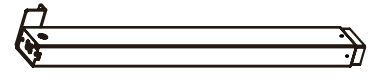
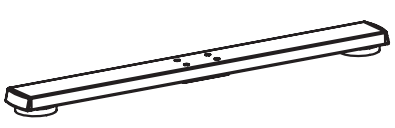
- A (x1) Leg
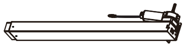
- B (x1) Motorized Leg
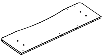
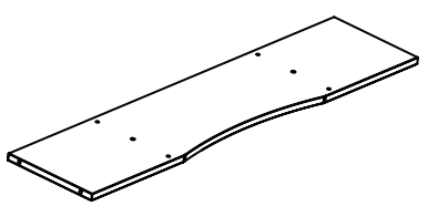
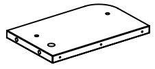
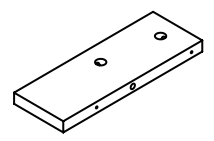
- C (x1) Front Desktop
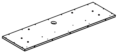
- D (x1) Back Desktop
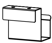
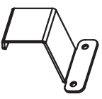
- E (x2) Side Bracket

- F (x2) Foot
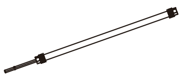
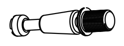
- G (x1) Sync Rod
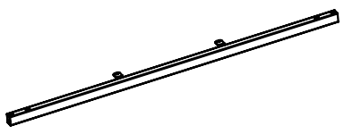
- H (x1) Crossbar
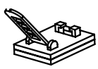
- I (x1) Tray
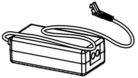
- J (x1) AC Adapter
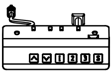
- K (x1) Control Panel
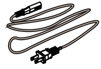
- L (x1) Power Cable
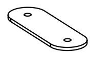
- M (x3) Connecting Plate
- N (x2) Hook
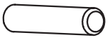
- O (x17) Wooden Dowel
- P (x1) Cable Management Cover

- Q (x5) Cable Clip
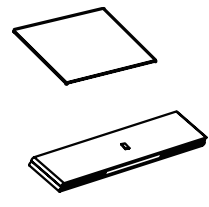
- R (x2) Drawer
- S (x4) Caster
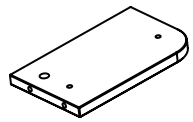
- T (x1) Lower Shelf Panel
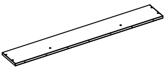
- U (x1) Back Shelf Panel
- V (x1) Right Shelf Panel
- W (x1) Left Shelf Panel
- X (x2) Shelf Brace
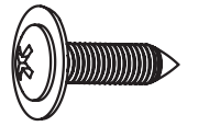
- S-A (x22) ST4.2x15mm Screw
- S-B (x4) M8x50mm Screw
- S-C (x4) M8x16mm Screw
- S-D (x8) M6x35mm Screw

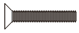
- S-E (x15) M4.2x40mm Screw

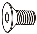
- S-F (x6) Cam Lock Screw
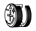
- S-G (x6) Cam Lock
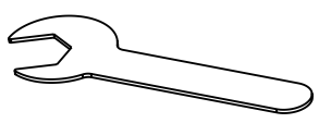
- T-A (x1) 14mm Wrench
- T-B (x1) 5mm Allen Wrench
- T-C (x1) 18mm Wrench

TOOLS NEEDED
- Level

- Drill

- Phillips Screwdriver

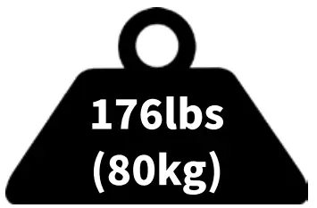
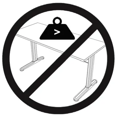
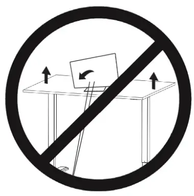
DO NOT EXCEED WEIGHT CAPACITY
Failure to do so may result in serious injury.
WARNING
PINCH POINT
DO NOT place hands on or near sup lit bars.1..yloving parts can crush and cut. Pinch points are created durians, kiting and lowering the worksurface. Failure to follow these instructions may result in serious pal injury.

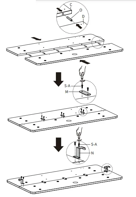
STEP 1
Place Front Desktop (C) and Back Desktop (D) upside down on a clean flat surface. Insert Wooden Dowels (O) into the holes in both desktops and slide them together. Use Connecting Plates (M) with ST4.2x15mm Screws (S-A) to secure the desktop assembly. Mount Hooks (N) to the desktop assembly using ST4.2x15mm Screws (S-A).
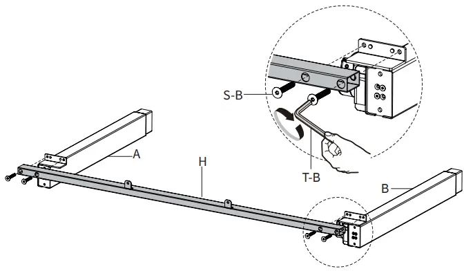
STEP 2
Assemble Crossbar (H) to Leg (A) and Motorized Leg (B) using M8x50mm Screw (S-B) and 5mm Allen Wrench (T-B)
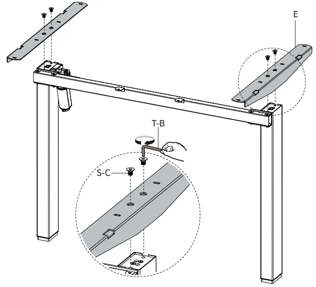
STEP 3
Mount Side Brackets (E) to the frame assembly using M8x16mm Screws (S-C) and 5mm Allen Wrench (T-B).
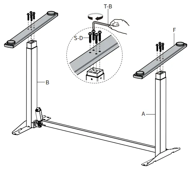
STEP 4
Place the frame assembly upside down and assemble Feet (F) to Leg (A) and Motorized Leg (B) using M6x35mm Screws (S-D) and 5mm Allen Wrench (T-B).
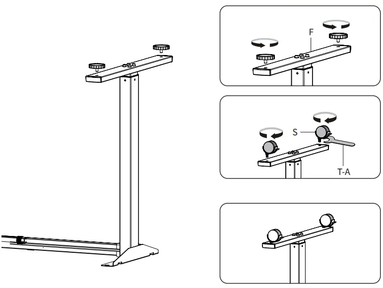
STEP 5
If desired, the foot pads on Feet (F) can be replaced with Casters (S). Unscrew the pads and thread Casters (S) onto Feet (F) using 14mm Wrench (T-A).
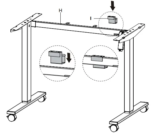
STEP 6
Place Tray (I) over Crossbar (H).
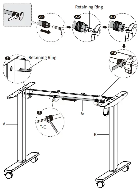
STEP 7
Loosen the knobs on Sync Rod (G) using 18mm Wrench (T-C) and extend the hex shaft. Insert the hex shaft into Leg (A), making sure the metal retaining ring makes contact with the leg. While holding the hex shaft with one hand, extend Sync Rod (G) onto the spline shaft of Motorized Leg (B). Retighten the knob using 18mm Wrench (T-C).
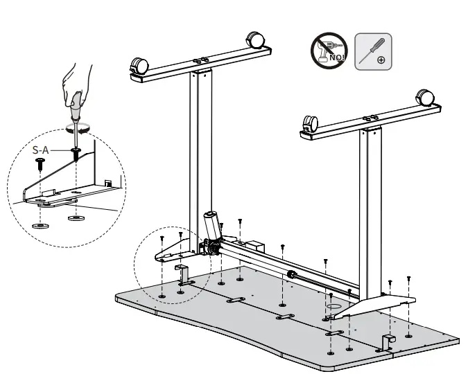
STEP 8
Secure the frame assembly to the desktop using ST4.2x15mm Screws (S-A) and a Phillips screwdriver.

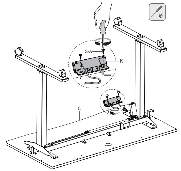
STEP 9
Assemble Control Panel (K) to Front Desktop (C) using ST4.2x15mm Screws (S-A) and a Phillips screwdriver.
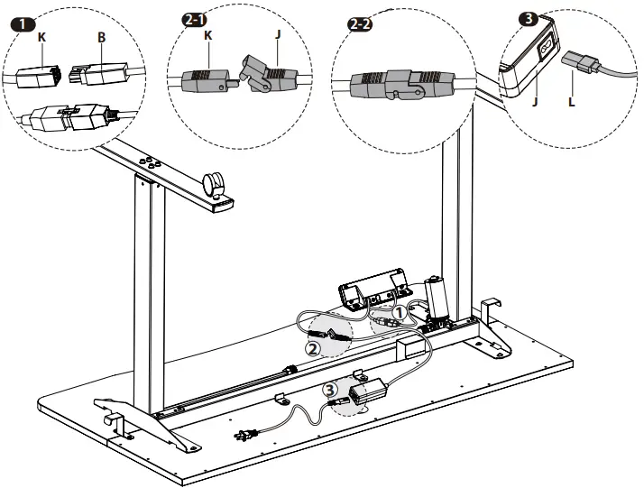
STEP 10
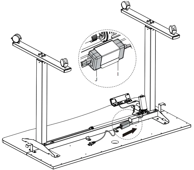
Plug the cable from Motorized Leg (B) into Control Panel (K). Connect Control Panel (K) and Power Cable (L) to AC Adapter (J).
STEP 11
Insert AC Adapter (J) into Tray (I).
STEP 12
Remove adhesive backing from Cable Clips (Q). Stick them to the underside of the desktop assembly, and manage cables.
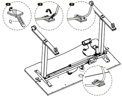
STEP 13
Insert Cable Management Cover (P) into Back Desktop (D).
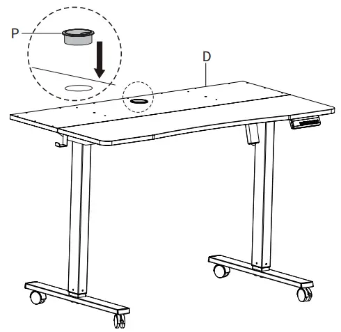
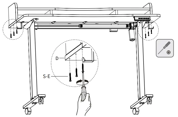
STEP 14
Assemble Shelf Braces (X) to Back Desktop (D) using Wooden Dowels (O) and ST4.2x40mm Screws (S-E).
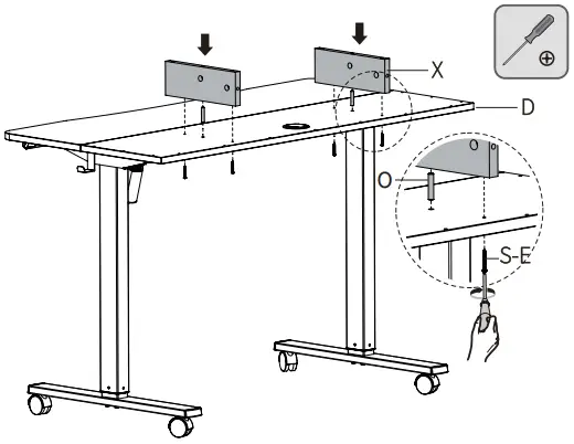
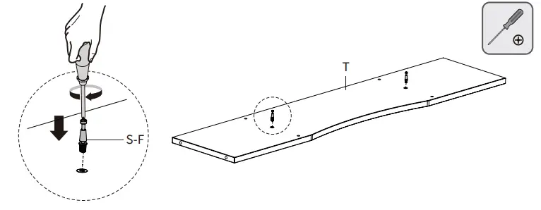
STEP 15
Insert Cam Lock Screws (S-F) into Lower Shelf Panel (T).
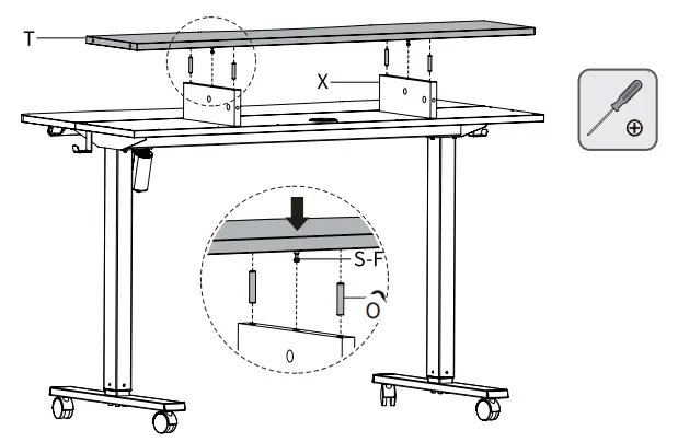
STEP 16
Assemble Lower Shelf Panel (T) to Shelf Braces (X) using Wooden Dowels (O) and Cam Lock Screws (S-F).
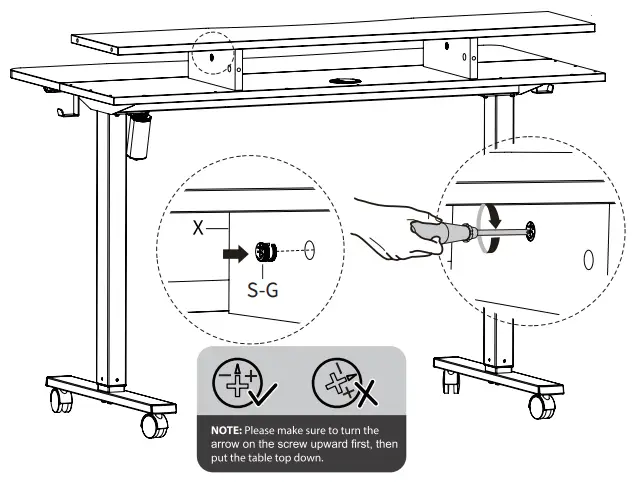
STEP 17
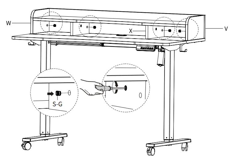
Insert Cam Locks (S-G) into the center hole in Shelf Braces (X).
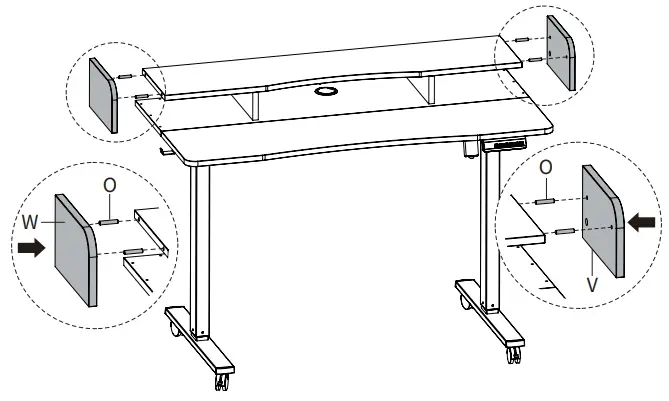
STEP 18
Assemble Right Shelf Panel (V) and Left Shelf Panel (W) to Lower Shelf Panel (T) using Wooden Dowels (O).
STEP 19
Secure the shelf assembly to Back Desktop (D) using ST4.2x40mm Screws (S-E).
STEP 20
Insert Cam Lock Screws (S-F) into Back Shelf Panel (U).
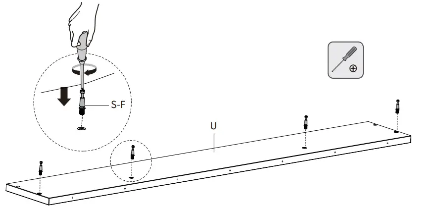
STEP 21
Assemble Back Shelf Panel (U) to the shelf assembly using Wooden Dowels (O).

STEP 22
Insert Cam Locks (S-G) into the rear holes of Right Shelf Panel (V), Left Shelf Panel (W), and Shelf Braces (X).
STEP 23
Secure Back Shelf Panel (U) to Back Desktop (D) using ST4.2x40mm Screws (S-E).

STEP 24
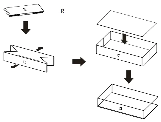
Unfold Drawers (R) and place the drawer insert inside.
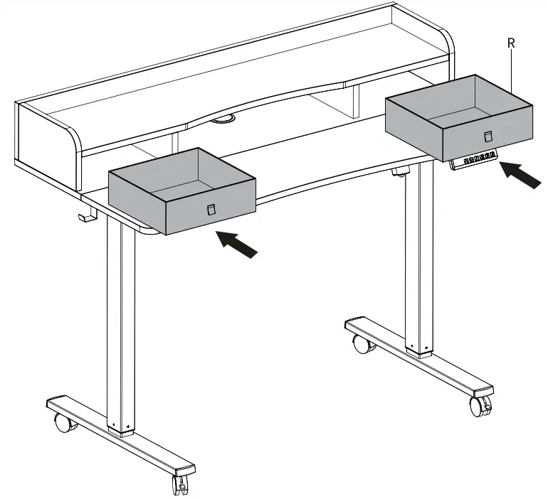
STEP 25
Insert Drawers (R) into the drawer assembly.
STEP 26
Plug Power Cable (L) into an AC power outlet. The desk is now ready for use. Please refer to the Control Panel User Guide for operational instructions.

CAUTION!
- Do not exceed desk weight limit.
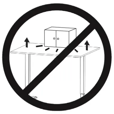
- Keep area of vertical motion free of obstacles.
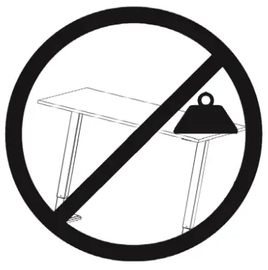
- Keep weight on desk balanced for correct operation and longer life of components.
- Leave enough slack in cables to allow for full range of vertical motion.
Failure to follow these instructions may result in property damage and/or personal injury.
![]() Love your new VIVO setup and want to share? Tag us in your photo! @vivo_us
Love your new VIVO setup and want to share? Tag us in your photo! @vivo_us
Customer Support
SKU: DESK-E-Y48SN
Scan the QR code with your mobile device or follow the link for helpful videos and specifications related to this product. Instruction Manual https://vivo-us.com/products/desk-e-y48sb
GET IN TOUCH | Monday-Friday from 7:00am-7:00pm CST
Open Monday – Friday 7:00am – 7:00pm CST,
our dedicated support team can offer immediate assistance with rapid response times. If any parts are received damaged or defective, please contact us. We are happy to replace parts to ensure you have a fully functioning product.
 309-278-5303 309-278-5303 |
AVG. RESOLUTION TIME (within office hrs): 5M 4S |
Chat live with an agent! |
AVG. RESOLUTION TIME (within office hrs): < 15 M |
AVG. RESPONSE TIME (within office hrs): 1HR 8M
|
FOR MORE VIVO PRODUCTS, CHECK OUT OUR WEBSITE AT: www.vivo-us.com
