![]() User manual
User manual
Retractable Thrusters
35 kgf / 55 kgf – ø 150 mm
60 kgf / 75 kgf / 95 kgf – ø 185 mm
Make sure that the user of the vessel is supplied with the owner’s manual.
Contents
Safety measures
Warning indications
Where applicable, the following warning indications are used in this manual in connection with safety:
Danger
Indicates that great potential danger exists that can lead to serious injury or death.
Warning
Indicates that a potential danger that can lead to injury exists.
![]() CAUTION
CAUTION
Indicates that the usage procedures, actions etc. concerned can result in serious damage to or destruction of the engine. Some CAUTION indications also advise that a potential danger exists that can lead to serious injury or death.
![]() note
note
Emphasises important procedures, circumstances etc.
Symbols
![]() Indicates that the relevant procedure must be carried out.
Indicates that the relevant procedure must be carried out.
![]() Indicates that a particular action is forbidden.
Indicates that a particular action is forbidden.
Warning!
When using the bow thruster watch out for swimmers or light boats which could be in the near vicinity of the bow thruster tunnel openings.
Pass on the safety instructions to others using the bow thruster.
Warning
This product should only be operated by persons who have read and understood the instructions and precautions in this manual.
Failure to follow the instructions in this manual may result in serious injury or property damage.
The manufacturer shall not be liable for any damages resulting from improper operation.
Warning!
Never operate the bow or stern thruster without load!
Switch off the bow or stern thruster immediately if it no longer provides thrust during operation!
General rules and laws with regard to safety and accident-prevention also need to be applied.
- Never touch the moving ends of the bow thruster whilst in operation.
- Never touch hot parts of the bow thruster and never place flammable materials in the vicinity of the bow thruster.
- Always stop the bow thruster before checking components or adjusting the bow thruster.
- Always disconnect the battery terminals during maintenance work.
- Ensure maintenance work is safe by only using tools suitable for the purpose.
- Always deactivate the main switch when the bow thruster is not in use for long periods.
Introduction
This manual give guidelines for operating the VETUS retractable bow thrusters ‘STE…’ .
Alterations made to the bow thruster by the user will void any li- ability on the part of the manufacturer for any damages that may result.
The actual thrust force, as performed by the bow thruster, will give different results with each individual vessel, depending on wind catch, displacement and shape of the underwater section.
The nominal thrust quoted can only be achieved under the most favourable conditions:
- Make sure that the batteries are supplying the correct voltage during use
- During the installation process the ‘Installation instructions for retractable for bow thrusters’, must be followed, specifically concerning:
– Sufficiently large diameter of the battery cables so that voltage drop is reduced to a minimum.
Following the above recommendations will result in longer life and better performance of your bow thruster. - For maintenance, please consult the ‘Maintenance and Warranty Book’ supplied.
- Never allow the bow thruster to operate for a long period; the maximum length of usage is restricted because of heat release in the electric motor. After use the motor must be allowed to cool down.
![]() note
note
The maximum continuous length of usage and the thrust as specified in the technical details are based on the recommended battery capacities and battery cables.
If significantly larger batteries in combination with very short battery cables of significantly larger diameter than recommended are used then the thrust will increase.
In such cases the maximum length of usage must be reduced in order to prevent damage to the motor.
Use
3.1 General
- Switch on the main switch.
After switching on the power supply on all panels the blue and red LED will flash alternately 3 times.
The system is now ‘stand-by’. The panel or both the panels are notactivated.
The thruster will remain retracted.
After switching on any panel the thruster will be automatically deployed.
![]() caution!
caution!
Do NOT switch in on the panel if the boat speed is more than 1.5 knot (3 km/hour)!
- Keep in mind that the carbon brushes in the motor release fine (black) dust. Do not store fragile equipment near the bow thruster motor.
Meaning LED indicator lights
For the meaning of the LED indicator lights, see table page 38
3.2 Switching ON a panel
- Press the ‘ON/OFF’ switch twice.
After the switch is pressed once the LED will flash blue and the buzzer will sound continuously didididididi….. (. . . . . . .) The ‘ON/OFF’ switch must be pressed a second time within 6 seconds.
![]() Note
Note
Deploying of the thruster will take approx. 6 seconds, during this time the LED will flash blue.
Once the thruster is fully deployed the LED will be on continuously blue.
The buzzer will confirm that the panel is ready for use by giving the signal dahdidah (- . -).
Two panels on one helm station
(one panel for a retractable bow thruster and one panel for a stern retractable thruster)
- Press twice on the ‘ON / OFF’ switch on one of the panels.
Both panels are switched on and bow and stern thruster will be deployed.
Consult the installation manual how to configure panels.
3.3 Switching on the other panel (in case of 2 panels)
To take over from one panel to the other the same procedure as switching on the first panel must be carried out.
Once the second panel is switched on the first one will be switched off.
The buzzer on the just switched off panel will reply with the signal didididahdidah ( . . . – . – ).
3.4 Control panel (Push-button or Joy-stick)
Use the joystick to operated the electric motor.
If the direction is changed from port to starboard or vice versa in one movement it will take about 1.5 seconds before the electric motor reacts.
This allows the electric motor to come to a stop before it has to rotate into another direction.
If a control panel is operated for more than 2 minutes at a time the electric motor will be switched off. A warning signal (. – . . -) will be heard as long as the switch is being operated. The LED will be on simultaneously red and blue.
Once the switch has been released and the LED has gone back to blue the electric motor can be switched on again.
![]() caution!
caution!
Always switch off the panel when manoeuvring is completed.
3.5 Switching OFF a panel
Press once the ‘ON/OFF’ switch once, the buzzer will beep once; after retracting the thruster the buzzer will reply with the sign didididahdidah ( . . . – . -).
Automatic switching off will take pace 15 minutes after the last operation of the joystick.
Here too, the buzzer will reply with the sign didididahdidah ( . . . – . – ).
- Switch off the main switch when leaving the ship.
3.6 Protections
Thermal protection of the motor
If the motor gets overheated it will be switched off and the panel will sound a warning signal once didahdididah ( . – . . – ).
At a panel which is ‘ON’, the LED flashes red and simultaneously blue is continuously on.
At a panel that is ‘OFF’ the LED flashes red.
Once the motor has cooled down sufficiently the panel will sound a signal dahdah ( – – ).
Now the motor can be switched on again.
Retracting of the thruster is disturbed
Retracting of the thruster is not possible because the actuator shear pin has been broken.
Approx. 10 seconds after switching off the panel once a warning signal didahdididah (.-..-) will sound and the LED will be on in red.
Reset the system after replacement of the shear pin by switching off and on the power supply to the thruster.
For replacement of the shear pin see ‘4 Trouble shooting’.
Power supply failure
During deployment of the thruster the power supply is witched off or a voltage dip occurs.
Once the power is back to normal will:
- a beep sound three times on the panel or on both the panels,
- the LED on the panel flashes blue,
- the thruster further first be fully deployed retracted immediately afterwards.
Press twice the ‘ON / OFF’ switch to turn on the panel to use the thruster.
Trouble shooting
Electric motor does not operate
- Check that the battery main switch is ‘ON’.
- Check whether the control panel fuse has burnt out. The control current fuse is in the bow thruster motor. A spare fuse can be found in the relay cap, see p. 42-45.
- Check if the main fuse has burnt out. See table on page 41 In all the above cases, the ‘POWER’ indicator LED is not lit.
- The electric motor has overheated and its thermal Protection has broken the circuit of the control current.
The panel gives a warning signal three times ( . – . . – ) and the LED will glow red.
As soon as the motor has cooled down enough, the LED will resume glowing blue and the bow thruster can be put back in service.
Check if it is possible to turn the propeller. A piece of wood or similar could have been caught between the propeller and the tunnel.
Electric motor turns slowly
- The battery is flat.
- Bad electrical connection(s) due to e.g. corrosion.
- The carbon brushes are not making proper contact.
- The battery capacity is reduced because of very low temperatures.
- Weed or fishing line has become caught in the propeller.
Control circuit fuse is burnt out [1]
- Short circuit in the operating circuit; check the wiring.
Electric motor turns (too) fast but there is no thrust
- The blades of the propeller have been damaged by a foreign object having entered the propeller or tunnel.
- The drive pin on the propeller shaft has been broken by a foreign object having entered the propeller or tunnel.
Replace the drive pin and check the propeller flange for any damage.
The shear pin of the actuator is broken
By mechanical overload, e.g. an obstacle has forced the hatch or cruising a high speed while the thruster is deployed, the shear pin can break.
- Make sure that the tunnel can move freely up and down and if necessary, eliminate the cause of the breaking of the pin.
- Remove the broken shear pin
- Remove the fuse from the power supply of the CAN bus signal
- Run the actuator with an external power supply to the retracted position until the motor is switched off by the end switch (change plus and minus, the direction changes).
- Turn the rod of the actuator inwards by hand until it does not go any further.
- Manually push the bow thruster motor to the retracted position of the actuator until it does not move any further and the holes of the actuator and holes on the bow thruster motor flange can be aligned by unscrewing the actuator stem.
![]() NoteDo not unscrew the rod too far, otherwise there is too little thread between the rod and the motor to transfer the forces.
NoteDo not unscrew the rod too far, otherwise there is too little thread between the rod and the motor to transfer the forces.
- Install new shear pin (1) and refitted the safety clips (2). Connect the cable running through the shear pin to the connector in the cable harness and on the other side to the cable from the bow thruster motor.
- Put the fuse back in the CAN-bus power cable.
- Reset the installation by operating the panel, with the bow thruster motor returning to its resting position.
The panel switches off.
The installation is ready for use.
Reset procedure retrectable bow or stern thruster
If the retrectable remains in an undesired position, there are two ways to reset the system.
- Press the on/off button until you hear an acoustic signal. After this, the retractable will return to its resting position.
- Switch off the main power supply of the bow thruster motor and remove the fuse from the CAN-bus power supply. Wait 10 seconds, first reinsert the CAN-bus fuse and then switch the bow thruster power supply back on.
The installation is ready for use.
Meaning LED indicator lights
| BLUE LED | RED LED | BUZZER | |
| Blinks (for 6s) | (.) (for 6s) | Childlock after the first push | |
| ON | ‘Ix (-.-) | Device is enabled, bow thruster is ready | |
| Blinks double | Device is inactive, thruster is active | ||
| Blinks fast | lx (.-..-) | Bow thruster is overheated | |
| OFF | lx (..) | Bow thruster was overheated | |
| Blinks fast | lx (.-..-) | Bow thruster supply is low | |
| Blinks fast | 3x (.) | Thruster is deployed, device not activated. | |
| ON | ON | lx (.-..-) | Actuator moves but time is up (possibly broken break pin) |
| ON | ON | lx (.-..-) | Bow thruster engaged for 2 minutes |
| Bow thruster | Fuse | |
| slow blow’ | slow blow’ | |
| STE5512D 55 kgf – 12 V | 250 A | ZE250 |
| STE6012D 60 kgf – 12 V | 200 A | ZE200 |
| STE7512D 75 kgf – 12 V | 355 A | ZE355 |
| STE9512D 95 kgf – 12 V | 425 A | ZE425 |
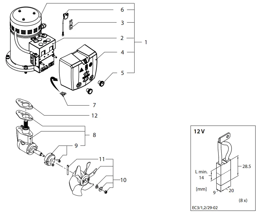
| STE5512D | Service parts | ||
| pos. | qty | part | description |
| 1 | 1 | 5E10060 | Electromotor 3 kW -12 V for STE5512D c/w solenoid switches |
| 2 | 1 | 5E10015 | Set of solenoid switches 12 V for STE5512D |
| 3 | 1 | 5E10126 | Set of 8 pcs of carbon brushes for STE5512D |
| 4 | 1 | BPC00100 | Relais cover |
| 1 | 5E10006 | Set of 2 pcs knurled nuts | |
| 6 | 1 | T5110 | Thermal Protection |
| 7 | 1 | BP256 | Spare fuse 5 A |
| 8 | 1 | 5E10078 | Tailpiece comp!. |
| 9 | 1 | 5E10149 | Zincanode c/w screws |
| 10 | 1 | 5E10087 | Propeller c/w drive pin and mounting set |
| 11 | 1 | BP1129 | Propeller pins, 5 pcs |
| 12 | 2 | BP1020 | Gasket |

| STE5512D | Service parts | ||
| pos. | qty | part | description |
| 1 | 1 | SET0060 | Electromotor 3 kW – 12 V for STE6012D c/w solenoid switches |
| 2 | 1 | SET0015 | Set of solenoid switches 12 V for STE6012D |
| 3 | 1 | SET0126 | Set of 8 pcs of carbon brushes for STE6012D |
| 4 | 1 | BPC00100 | Relais cover |
| 5 | 1 | SET0006 | Set of 2 pcs knurled nuts |
| 6 | 1 | TS110 | Thermal Protection |
| 7 | 1 | BP256 | Spare fuse 5 A |
| 8 | 1 | SET0091 | Tailpiece compl. |
| 9 | 1 | SET0150 | Zincanode c/w screws |
| 10 | 1 | SET0088 | Propeller c/w drive pin and mounting set |
| 11 | 1 | BP275S | Propeller pins, 5 pcs |
| 12 | 2 | BP1020 | Gasket 2 mm |

| STE5512D | Service parts | ||
| pos. | qty | part | description |
| 1 | 1 | SET0031 | Electromotor 4.4 kW – 12 V for STE7512D c/w solenoid switches |
| 2 | 1 | SET0015 | Set of solenoid switches 12 V for STE7512D |
| 3 | 1 | SET0126 | Set of 8 pcs of carbon brushes for STE7512D |
| 4 | 1 | BPC00100 | Relais cover |
| 5 | 1 | SET0006 | Set of 2 pcs knurled nuts |
| 6 | 1 | TS110 | Thermal Protection |
| 7 | 1 | BP256 | Spare fuse 5 A |
| 8 | 1 | SET0035 | Tailpiece compl. |
| 9 | 1 | SET0150 | Zincanode c/w screws |
| 10 | 1 | SET0088 | Propeller c/w drive pin and mounting set |
| 11 | 1 | BP275S | Propeller pins, 5 pcs |
| 12 | 2 | BP1020 | Gasket 2 mm |
| STE5512D | Service parts | ||
| pos. | qty | part | description |
| 1 | 1 | SET0041 | Electromotor 5.7 kW – 12 V for STE9512D c/w solenoid switches |
| 2 | 2 | SET0111 | Set of solenoid switches 12 V for STE9512D |
| 3 | 3 | SET0128 | Set of 8 pcs of carbon brushes for STE9512D |
| 4 | 4 | BPC00200 | Relais cover |
| 5 | 5 | SET0006 | Set of 2 pcs knurled nuts |
| 6 | 6 | TS110 | Thermal Protection for STE9512D |
| 7 | 7 | BP256 | Spare fuse 5 A |
| 8 | 8 | SET0046 | Tailpiece compl. |
| 9 | 9 | SET0150 | Zincanode c/w screws |
| 10 | 10 | SET0088 | Propeller c/w drive pin and mounting set |
| 11 | 11 | BP275S | Propeller pins, 5 pcs |
| 12 | 12 | BP1020 | Gasket 2 mm |
Fokkerstraat 571 – 3125
BD Schiedam – Holland
Tel.: +31 (0)88 4884700
– [email protected] –
www.vetus.com
Printed in the Netherlands
020584.06 2023-11