vetus HPW Series Waterlock Exhaust System

Contents
Safety
Warning indications
The following warning indications are used in this manual in the context of safety:
 Danger
Indicates that great potential danger exists that can lead to serious injury or death.
Warning
Indicates that a potential danger that can lead to injury exists.
 Caution
Indicates that the usage procedures, actions etc. concerned can result in serious damage to or destruction of the engine. Some CAUTION indications also advise that a potential danger exists that can lead to serious injury or death.
 Note
Note
Emphasis’s important procedures, circumstances etc.
Symbols
 Indicates that the relevant procedure must be carried out.
 Indicates that a particular action is forbidden.
Share these safety instructions with all users.
General rules and laws concerning safety and accident prevention must always be observed
Introduction
The VETUS exhaust system components are especially suitable for use in water-injected exhaust systems.
The maximum temperature when in continuous use is 250 °C.
- Fit a temperature alarm to warn of excessively hot exhaust system temperature.
If the quantity of injected coolant water is reduced to in order to lower back-pressure in the exhaust system, check that there is still sufficient water injected when the engine is ticking-over. This will prevent excess temperatures in the exhaust system. - Excess temperature can also be the consequence of insufficient mixing of coolant water with the exhaust gasses.
In general, good mixing is obtained by a virtually vertically installed exhaust injection bend.
Poor mixing can also occur with an engine on tick-over; especially when the coolant water injection bend is installed virtually horizontally.
If necessary, make provisions to improve the mixing of coolant water with the exhaust gases. Do this by fitting a water swirler or a water mixer in the exhaust pipe.
With water-injected exhaust systems, fit a hose of suitable quality.
This hose must be reinforced, resistant to exhaust gasses, high temperatures (100 degrees °C, 212 degrees F) and oil. Easy flexibility is essential for installation, while the hose must not collapse when heated.
VETUS exhaust hose fulfils all the above requirements.
Make sure that the user of the vessel is supplied with the owner’s manual.
Installation
Installing waterlock HPW
Instal the water lock as vertical as possible.
Position the water lock ‘back-to-front’ alongside the engine when there is insufficient space behind the engine.
Because the water lock contains water during use, the weight increases significantly. The water lock must therefore be mounted on the deck, as is indicated in the drawing.

Note
Make sure the following conditions are met under all sailing conditions (e.g. heeling):
- The waterlock ‘IN’-connection is located below the level of the exhaust injection bend.
- the distance between the bottom of the engine’s cooling water outlet and the highest point of the waterlock is at least 5 cm (2″).
For additional exhaust system information see chapter 4.
Installing the transom exhaust connection
Fit the transom exhaust connection at such a position that with the ship fully laden, the outlet is still at least 5 cm (2”) above the waterline.
Exhaust pipe
In order to ensure the proper drainage of the coolant water injected into the exhaust pipe, the pipe must be installed with a slope downward over its whole length from the water injection point to the water lock.
Warning
During operation, the exhaust pipe will contain water. This will increase its weight considerably, so support the exhaust pipe properly.
The exhaust pipe from waterlock to transom connection must be installed in such a way that:
- The highest point in the exhaust pipe should not be more than 150 cm (60”) above the underside of the waterlock.
- The length of the section between the waterlock and the highest point, should not exceed 300 cm (120”).
Hose connections

In order to achieve the ideal connection between the hoses and the water lock, both hose connections turn through 360 degrees.
Loosen the bolts before turning the hose connections!
Tighten the hose connections to a torque of 1 Nm (0.75 ft.lb).
|
Type |
Volume | Ø IN | Ø OUT | Maximum engine power* |
|
HPW102 |
55 liter | 102 mm | 102 mm |
100 kW (136 hp) |
| HPW127 | 127 mm | 127 mm |
155 kW (211 hp) |
|
|
HPW152 |
152 mm | 152 mm | 222 kW (302 hp) | |
| HPW127152 | 127 mm | 152 mm |
188 kW (256 hp) |
|
|
HPW203 |
130 liter | 203 mm | 203 mm | 409 kW (557 hp) |
| HPW250 | 250 mm | 250 mm |
621 kW (846 hp) |
|
|
HPW152203 |
152 mm | 203 mm | 313 kW(426 hp) | |
| HPW203250 | 203 mm | 250 mm |
510 kW (694 hp) |
|
|
HPWL152 |
152 mm | 152 mm |
229 kW (312 hp) |
* Based on an allowed back pressure of 0.1 bar.

The top portion of the waterlock can be turned in a 360˚ radius.
The top portion should be turned as follows:
- Unscrew the clamping strip
- Turn the top portion to the desired position
- Tighten the clamping strip sufficiently, to a torque of 5 Nm (3,7 ft.lb).
Fitting the hose
To ease the fitting of the hose to the hose connector, use only water and/or soap, NOT grease or products containing oil.
Fit each hose connection with 2 stainless steel 12 mm (0.5”) wide hose clamps.
Sensor for temperature alarm
A sensor for a temperature alarm can be fitted in the exhaust pipe.
Installation Examples
Exhaust systems with a waterlock type HPW, goose neck type LT and a transom connection are shown on page 21.
Entry of water from the aft is almost completely prevented by the extra height difference in the goose neck.
When the engine is stopped, any water which is still in the exhaust pipe (between the highest point in the exhaust system and the exhaust silencer) will run back to the exhaust silencer.
To reduce the amount of this water as much as possible, the goose neck should be fitted directly above the exhaust silencer, if possible (see drawings 1 and 3).
When the goose neck is fitted directly to the transom (drawings 2 and 4), the maximum length of the exhaust pipe, between exhaust silencer and the highest point, should be taken into account.
Prevention of syphoning (drawings 3 & 4)
If the water injection point ‘C’ is below, or less than 15 cm (0.6”) above the waterline (also when the ship heels under sail), there is a risk that when the engine is stopped, the coolant water will enter the engine due to syphoning. This syphoning can be prevented in two ways:
① By creating an air vent system in the coolant water hose between engine block and water injection point ‘C’, by fitting an air vent with air vent pipe, for example.
The air vent pipe must be connected to its own hull outlet (H).
② By fitting an air vent (with valve) in the coolant water hose between the engine block and water injection point ‘C’.
Use
Warning
If water enters the engine from the water lock into the exhaust system (for example: under sail when the ship rolls or pitches heavily) this will lead to irreparable damage to the engine.
Too much water in the water lock can effect engine starting; drain off this water first. Too much water in the water lock can be also caused by repeated starting attempts while the engine refuses to start.
Maintenance
- Check all hose connections for gas and water leaks regularly.
- Before the winter lay-up, drain the water lock. The water lock has one drain plug for this purpose.

Installation example
1 & 2:


Exhaust systems with water-injection point ‘C’ 15 cm or more above the waterline
|
‘A’ |
‘B’ | C’ |
| Exhaust manifold | Cooling water |
Water-injection point |
3 & 4:


Exhaust systems with water-injection point ‘C’ below or less than 15 cm above the waterline
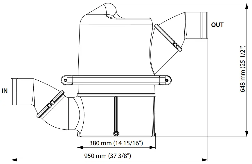
Principal dimensions
HPW (55 l)
|
|
Ø IN | Ø OUT |
| HPW102 | 102 mm (4”) |
102 mm (4”) |
|
HPW127 |
127 mm (5”) | 127 mm (5”) |
|
HPW152 |
152 mm (6”) |
152 mm (6”) |
| HPW127152 | 127 mm (6”) |
152 mm (6”) |
HPW (130 l)
|
|
Ø IN | Ø OUT |
|
HPW203 |
203 mm (8”) |
203 mm (8”) |
| HPW250 | 250 mm (9 13/16″) |
250 mm (9 13/16″) |
|
HPW152203 |
152 mm (6”) | 203 mm (8”) |
| HPW203250 | 203 mm (8”) |
250 mm (9 13/16″) |
|
HPWL152 |
152 mm (6”) |
152 mm (6”) |

Customer Support
Fokkerstraat 571
3125 BD Schiedam
Holland
Tel.: +31 (0)88 4884700
[email protected]
www.vetus.com
