V-TAC VT-15 LED Bulk Head

Contents
INTRODUCTION & WARRANTY
Thank you for selecting and buying V-TAC Product. V-TAC will serve you the best. Please read these instructions carefully before starting the installing and keep this manual handy for future reference. If you have any another query, please contact our dealer or local vendor from whom you have purchased the product. They are trained and ready to serve you at the best. The warranty is valid for 5 years from the date of purchase. The warranty does not apply to damage caused by incorrect installation or abnormal wear and tear. The company gives no warranty against damage to any surface due to incorrect removal and installation of the product. The products are suitable for 10-12 Hours Daily operation. Usage of product for 24 Hours a day would void the warranty. This product is warranted for manufacturing defects only.
WARNING
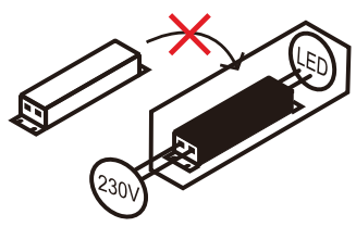
- Please make sure to turn off the power before starting the installation.
- The light source of this luminaire is not replaceable, when the light source reaches its end of life the whole luminaire should be replaced.
- Installation must be performed by a qualified person.
- If the external flexible cable or cord of this luminaire is damaged, it shall be exclusively replaced by the manufacturer or his service agent or a similar qualified person in order to avoid a hazard.
 This marking indicates that this product should not be disposed of with other household wastes.
 Caution, risk of electric shock.
- Non-replaceable control gear.
- Non-replaceable light source.

INSTALLATION INSTRUCITONS
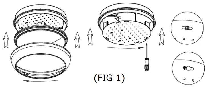
STEP 1
Remove the cover by twisting the diffuser anti-clockwise and set aside. Carefully remove the LED tray and unplug it from the LED driver, and set aside.
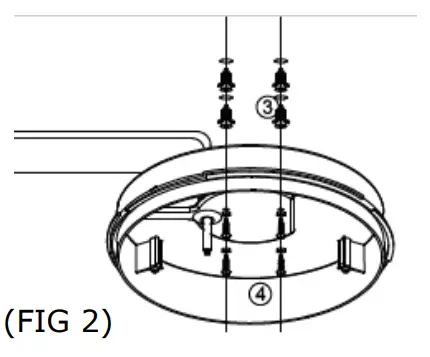
STEP 2
Hold the product in place, mark & drill the holes into the wall and nail the alligator into the hole.
STEP 3
Make the AC Power connection through the waterproof rubber cap.

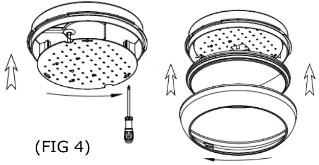
STEP 4
Install the LED tray and diffuser back. Switch ON the power to test the light.
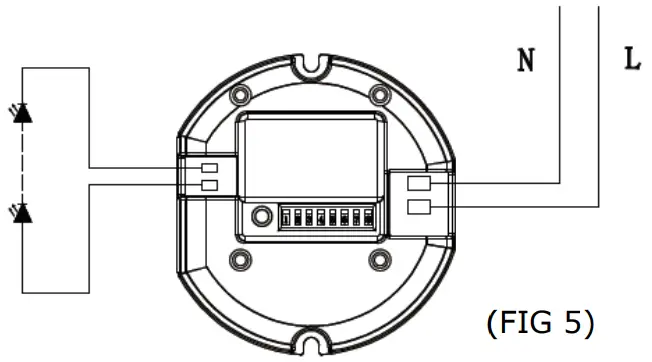
SENSOR WIRING DIAGRAM
SENSOR SETTINGS
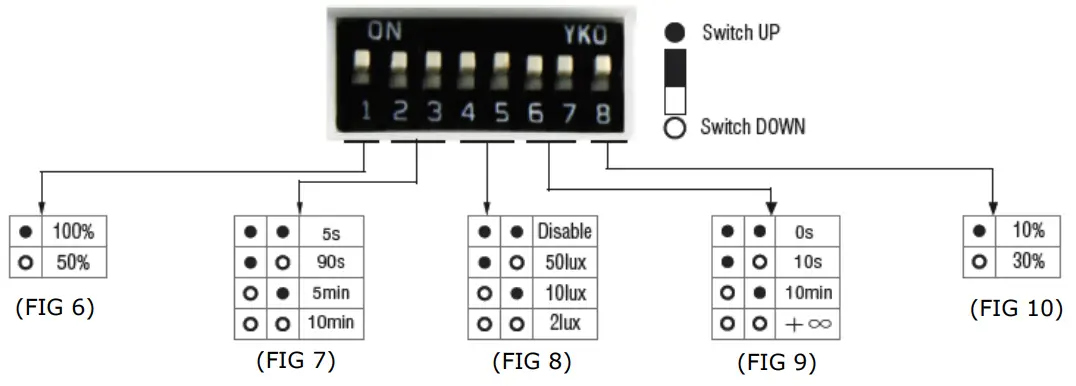
Detection Area – It can be adjusted by combining DIP switches for specific application [FIG 6].
Hold Time – Time period during which the light will be ON after the last detection [FIG 7].
Daylight Threshold – Daylight sensor priors motion sensor. Set Threshold for Specific needs. If disabled, only motion
sensor will work [FIG 8].
Stand-by Period – This is the time period during which the light keeps dimming down after the last detection [FIG 9].
Stand-by dimming level – The dimming level during which the light is ON during the stand-by Period [FIG 10].
APPLICATION (Function Demo – Dimmable Control/Corridor function)
When motion is detected, but the daylight is sufficient, the light will remain OFF.
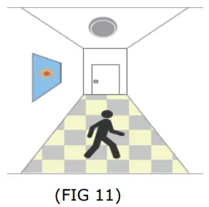
When motion is detected, and the daylight is insufficient, the light will be ON.

After last detection, the light will be dimmed down to stand-by dimming level (10%, 30%).
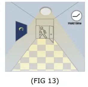
After a stand-by period, the light will switch OFF.


TECHNICAL DATA:
|
MODEL |
WATTS | LUMENS | BEAM ANGLE | BODY TYPE | CR | INPUT POWER | DIMENSION | MICROWAVE SENSOR |
EMERGENCY BACKUP |
|
VT-11 |
8W | 720 | 120° | PC | >80 | AC:200-240V, 50/60Hz | 320x100mm | NO | NO |
| VT-15 | 15W | 1400 | 120° | PC | >80 | AC:200-240V, 50/60Hz | 320x100mm | NO |
NO |
|
VT-16 |
15W | 1400 | 120° | PC | >80 | AC:200-240V, 50/60Hz | 320x100mm | YES |
YES |


IN CASE OF ANY QUERY/ISSUE WITH THE PRODUCT, PLEASE REACH OUT TO US AT: [email protected]
FOR MORE PRODUCTS RANGE, INQUIRY PLEASE CONTACT OUR DISTRIBUTOR OR NEAREST DEALERS.
V-TAC EUROPE LTD. BULGARIA, PLOVDIV 4000, BUL.L.KARAVELOW 9B.
