![]() INNOVATIVE LED LIGHTING
INNOVATIVE LED LIGHTING

5 YEAR WARRANTY*
WEE Number:80133970
INSTALLATION INSTRUCATION
Contents
TECHNICAL DATA
| SKU | 11410 |
| MAX INPUT CURRENT | MAX 0.3A |
| INPUT VOLTAGE | AC:220-240V, 50/60Hz |
| RATED POWER | 40W(MAX) |
| PF | >0.9 |
| AMBIENT TEMPERATURE (ta | 45°C |
| CRITICAL TEMPERATURE (tc | 90°C |
| OUTPUT POWER | DC:9-38V |
| INPUT STANDBY MODE | 0.75-1.5mm² |
| OUTPUT STANDBY MODE | 0.5-1.0mm² |
| STANDBY POWER (Psb) | Psb<0.5W |
| EFFICIENCY IN FULL-LOAD | >83% |
INTRODUCTION & WARRANTY
Thank you for selecting and buying V-TAC product. V-TAC will serve you the best. Please read these instructions carefully before starting the installation and keep this manual handy for future reference.
If you have any another query, please contact our dealer or local vendor from whom you have purchased the product. They are trained and ready to serve you at the best. The warranty is valid for 5 years from the date of purchase. The warranty does not apply to damage caused by incorrect installation or abnormal wear and tear. The company gives no warranty against damage to any surface due to incorrect removal and installation of the product. The products are suitable for 10-12 Hours Daily operation. Usage of product for 24 Hours a day would void the warranty. This product is warranted for manufacturing defects only.
 This marking indicates that this product should not be disposed of with other household wastes.
![]() Caution, risk of electric shock.
Caution, risk of electric shock.
WARNING:
- Please make sure to turn off the power before starting the installation.
- Observe the connection diagram provided before connecting to the power supply
- Installation should be done by a qualified electrician.
- Disconnect the power supply when wiring or soldering the LED.
- Please ensure to check the DC output of the power supply matches with the DC Input of the Panel.
- For LED Modules only
- For Infoor use only
WIRING DIAGRAM OF TRIAC DIMMING OPERATION:
 NOTE: The dimmable driver cannot no-load
DIMMING OPERATION:
PRODUCT TERMINALS
| INPUT | |
| AC-L | Input terminal of AC live wire |
| AC-N | Input terminal of AC neutral wire |
| OUTPUT | |
| LED+ | Positive electrode output of LED driver |
| LED- | Negative electrode output of LED driver |
OUTPUT CURRENT ADJUSTABLE VIA A BUILT-IN DIP SWITCH
| CURRENT ADJUSTMENT TABLE | ||||||
| Output Voltage | Output Current | 1 | 2 | 3 | 4 | DIP Switch Diagram |
| 9-38Vdc | 1050mA | ON | ON | ON | ON | 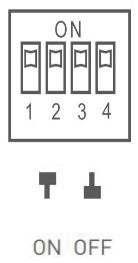 |
| 9-40Vdc | 1000mA | ON | ON | ON | OFF | |
| 9-42Vdc | 950mA | OFF | ON | ON | ON | |
| 9-42Vdc | 900mA | OFF | ON | ON | OFF | |
| 9-42Vdc | 850mA | OFF | OFF | ON | ON | |
| 9-42Vdc | 800mA | OFF | OFF | ON | OFF | |
| 9-42Vdc | 750mA | OFF | OFF | OFF | ON | |
| 9-42Vdc | 700mA | OFF | OFF | OFF | OFF | |
INSTALLATION:
- Please make sure to turn off the power before starting the installation.
- Connect the AC input source to the power supply and the AC plug (not in the scope of delivery included). AC plugs can be bought in any hardware store.
- Wire the DC output of the power supply unit to the LED Panel.
- Plug the power adapter into the socket to illuminate the whole system.
![]() IN CASE OF ANY QUERY/ISSUE WITH THE PRODUCT PLEASE REACH OUT TO US AT
IN CASE OF ANY QUERY/ISSUE WITH THE PRODUCT PLEASE REACH OUT TO US AT
[email protected] V-TAC HOUSE, KELPATRICK ROAD, SLOUGH, BERKSHIRE, SL1 6BW, UK.