![]() Triple Monitor Desk Mount
Triple Monitor Desk Mount
Instruction Manual SKU: STAND-V103
Contents
STAND-V103 Triple Monitor Desk Mount
Scan the QR code with your mobile device or follow the link for helpful videos and specifications related to this product. https://vivo-us.com/products/stand-v103
GET IN TOUCH
Monday-Friday from 7:00am-7:00pm CST
| [email protected] | www.vivo-us.com Chat live with an agent! |
309-278-5303 |
WARNING!
If you do not understand these directions, or if you have any doubts about the safety of the installation, please call a qualified technician. Check carefully to make sure there are no missing or defective parts. Improper installation may cause damage or serious injury. Do not use this product for any purpose that is not explicitly specified in this manual. Do not exceed weight capacity. We cannot be liable for damage or injury caused by improper mounting, incorrect assembly or inappropriate use.
TIPOVER WARNING
SERIOUS OR FATAL CRUSHING INJURIES CAN OCCUR FROM TIPOVER. TO HELP PREVENT TIPOVER:
- NEVER ALLOW CHILDREN TO CLIMB, STAND, HANG, OR PLAY ON ANY PART OF MONITOR OR STAND.
- USE TIPOVER RESTRAINT OR ANCHOR STAND TO WALL USE OF TIPOVER RESTRAINTS MAY ONLY REDUCE, BUT NOT ELIMINATE RISK OF TIPOVER.
WARNING: CHOKING HAZARD
SMALL PARTS – NOT FOR CHILDREN UNDER 3 YEARS. ADULT SUPERVISION IS REQUIRED.
PACKAGE CONTENTS
 NOTE: SOME HARDWARE MAY NOT BE USED
TOOLS NEEDED
![]() DO NOT EXCEED WEIGHT CAPACITY.
DO NOT EXCEED WEIGHT CAPACITY.
Failure to do so may result in serious injury.
ASSEMBLY STEPS
STEP 1
OPTION A: Clamp Installation
Install Upper Clamp (C) to Pole (A) using M6x8mm Screws (S-A) and a Phillips screwdriver. Assemble Lower Clamp (B) to Upper Clamp (C) using M10x15mm Screws (S-B) and 5mm Allen Wrench (T-B). Secure the clamp assembly to the desktop be tightening to the hand bolts on Lower Clamp (C). Install the Pole Cover (D) to Pole (A). OPTION B: Existing Grommet Base Installation
Remove adhesive backing from Grommet Pad (L) and place on the bottom of Pole (A). Install Pole (A) to existing grommet hole using Support Plate (I) with M10 Bolt (S-F), M10 Washer (S-E) and Lock Washer (S-G). Tighten with Wrench (T-D). Install the Pole Cover (D) to Pole (A). OPTION C: Self-Drilled Grommet Base Installation
Drill a 3/8” (10mm) diameter hole through the mounting surface Remove adhesive backing from Grommet Pad (L) and place on the bottom of Pole (A). Install Pole (A) to existing grommet hole using Support Plate (I) with M10 Bolt (S-F), M10 Washer (S-E) and Lock Washer (S-G). Tighten with Wrench (T-D). Install the Pole Cover (D) to Pole (A). STEP 2
Align Arm Extensions (F) with Arm (E) so that the holes for the wire clips are facing down. Place Plastic Spacers (H) on top and bottom of Arm Extensions (F). Assemble Arm Extensions (F) to Arm (E) with M10x47mm Screws (S-C) and tighten using 6mm Allen Wrench (T-C). Press Joint Covers (G) into place. STEP 3
Assemble Arm (E) to Pole (A) using M8x10mm Screws (S-D) and 5mm Allen Wrench (T-B). STEP 4
OPTION A: Flat Back Monitor
Secure Side VESA Plates (K) to monitors using M4x12mm Thumbscrews (M-A).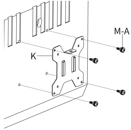 Secure Center VESA Plate (J) to monitors using M4x12mm Thumbscrews (M-A).
 OPTION B: Curved Back Monitor
Secure Side VESA Plates (K) to monitors using M4x30mm Screws (M-B) and M4 Spacers (M-C). Secure Center VESA Plate (J) to monitors using M4x30mm Screws (M-B) and M4 Spacers (M-C).
 STEP 5
Assemble side VESA Plates (K) with monitors to Arm Extensions (F). Secure using Cap Nuts (S-I). Assemble Center VESA Plate (J) with monitor to Arm (E). Secure using M4x6mm Screw (S-H).
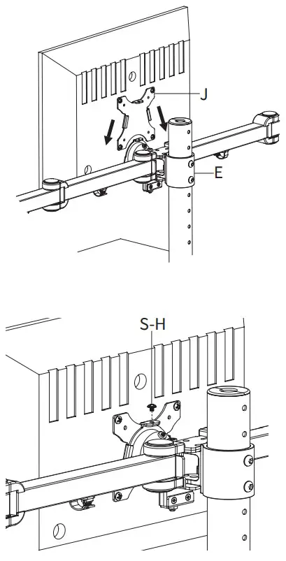 STEP 6
Remove the plastic covers on Arm Extensions (F) and adjust the tilt using Wrench (T-D). Adjust the Tilt and rotation of the center monitor by loosening the set screw on Arm (E) using 3mm Allren Wrench (T-A). Retighten the set screw.
 STEP 7
Adjust the Height of Center Monitor:
Using 6mm Allen Wrench (T-C), turn the bolt on Arm (E) counterclockwise tolower the center monitor, turn the bolt clockwise to raise the center monitor.  Adjust the Height of Side Monitors:
Remove Cap Nut (S-I) from Arm Extensions (F). Turn the screw using counterclockwise using 3mm Allen Wrench (T-A) to raise the monitor, and clockwise to lower it. STEP 8
Remove Joint Covers (G) from Arm (E) to adjust the tension using 6mm Allen Wrench (T-C). STEP 9
Insert Cable Clips (M) into the undersides of Arm (E) and Arm Extensions (F). Route cables through Cable Clips (M) and Pole (A). Love your new VIVO setup and want to share?
Tag us in your photo! @vivo_us
Open Monday – Friday 7:00am – 7:00pm CST, our dedicated support team can offer immediate assistance with rapid response times. If any parts are received damaged or defective, please contact us. We are happy to replace parts to ensure you have a fully functioning product.
| 309-278-5303 | AVG. RESOLUTION TIME (within office hrs): 5M 4S | |
| www.vivo-us.com Chat live with an agent! |
VG. RESOLUTION TIME (within office hrs): < 15 M | |
| [email protected] | AVG. RESPONSE TIME (within office hrs): 1HR 8M – 23% within < 15m – 38% within < 30m – 61% within < 1hr – 83% within < 2hr – 92% within < 3hr |
FOR MORE VIVO PRODUCTS, CHECK OUT OUR WEBSITE AT: www.vivo-us.com
![]() LAST UPDATED: 06/13/2022
LAST UPDATED: 06/13/2022