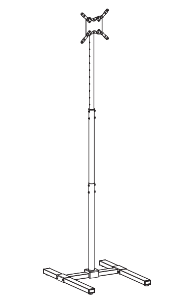
V I V O STAND-TV17 Black TV Stand for Treadmills and Ellipticals
Contents
 WARNING!
If you do not understand these directions, or if you have any doubts about the safety of the installation, please call a qualified technician. Check carefully to make sure there are no missing or defective parts. Improper installation may cause damage or serious injury. Do not use this product for any purpose that is not explicitly specified in this manual. Do not exceed weight capacity. We cannot be liable for damage or injury caused by improper mounting, incorrect assembly or inappropriate use.
TIPOVER WARNING
SERIOUS OR FATAL CRUSHING INJURIES CAN OCCUR FROM TIPOVER. TO HELP PREVENT TIPOVER:
- NEVER ALLOW CHILDREN TO CLIMB, STAND, HANG, OR PLAY ON ANY PART OF TV OR TV CART.
- USE TIPOVER RESTRAINT OR ANCHOR STAND TO WALL
USE OF TIPOVER RESTRAINTS MAY ONLY REDUCE, BUT NOT ELIMINATE RISK OF TIPOVER.
PACKAGE CONTENTS
|
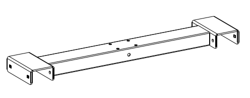
A (x1) Base |
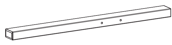
B (x2) Feet |
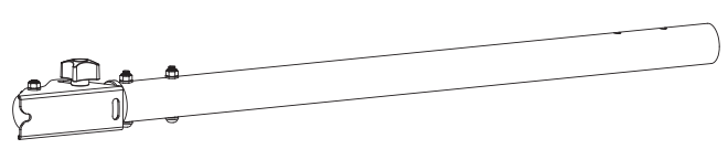
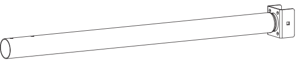
C (x1) Upper Pole |
D (x1) Lower Pole |
|
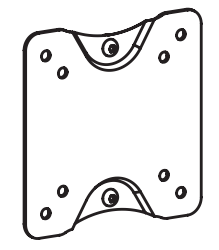
E (x1) VESA Plate |
F (x2) VESA Adapter |
G (x2) VESA Adapter |
H (x4) Foot Pad |
|
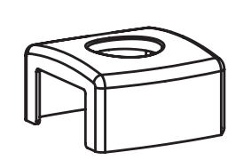
I (x1) Plastic Cover |
|||
|
S-A (x8) M5x10mm Screw |
S-B (x8) M5 Nut |
S-C (x2) M6x50mm Screw |
S-D (x5) M6x65mm Carriage Bolt |
|
S-E (x9) M6 Washer |
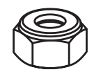
S-F (x7) M6 Lock Nut |
S-G (x1) M6 Flange Nut |
S-H (x4) M6x12mm Screw |
|
M-A (x4) M4x14mm Screw |
M-B (x4) M5x14mm Screw |
M-C (x4) M6x14mm Screw |
M-D (x4) M8x20mm Screw |
|
M-E (x4) M5 Washer |
M-F (x4) M8 Washer |
M-G (x8) Spacer |
T-A (x1) 5mm Allen Wrench |
|
T-B (x1) Wrench |
|||


NOTE: SOME HARDWARE INCLUDED MAY NOT BE USED
 |
DO NOT EXCEED WEIGHT CAPACITY. Failure to do so may result in serious injury. |
TOOLS NEEDED
- Phillips Screwdriver

WARNING: CHOKING HAZARD
SMALL PARTS – NOT FOR CHILDREN UNDER 3 YEARS. ADULT SUPERVISION IS REQUIRED.
ASSEMBLY STEPS
STEP 1
Secure Foot Pad (H) to underside of Feet (B).

Turn Feet (B) right side up. Attach Base (A) to Feet (B) using M6x65mm Carriage Bolts (S-D), M6 Washers (S-E), and M6 Lock Nuts (S-F). Tighten using Wrench (T-B).


STEP 2
Remove the two screws, four washers, and two nuts from Upper Pole (C) using 5mm Allen Wrench (T-A) and Wrench (T-B). Separate Center Pole (C) into two segments.
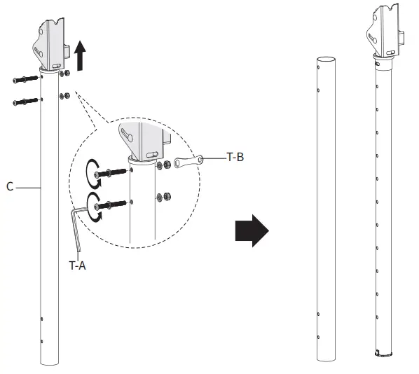
STEP 3
Slide Plastic Cover (I) over Lower Pole (D). Assemble the Upper Pole (C) segments using the previously removed hardware and M6x50mm Screws (S-C), M6 Washers (S-E), and M6 Lock Nuts (S-F). Tighten using 5mm Allen Wrench (T-A) and Wrench (T-B).

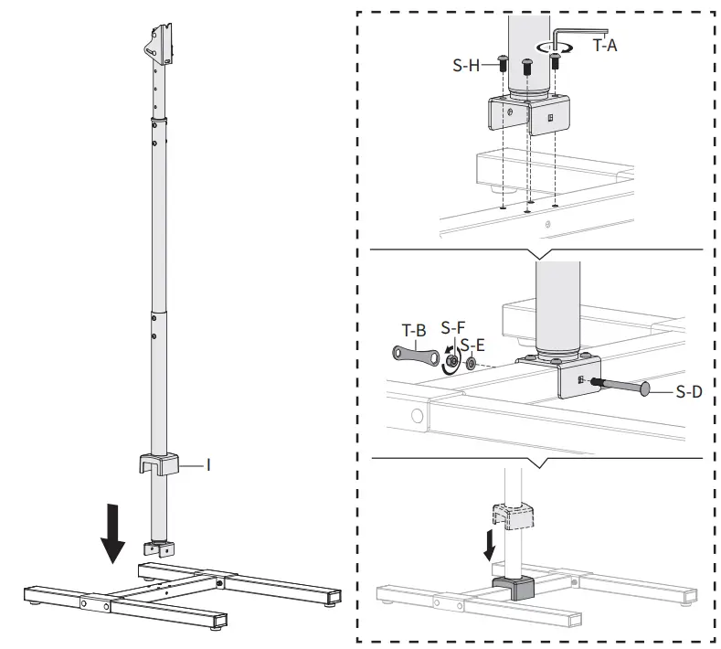
STEP 4
Lift Plastic Cover (I) and connect assembled pole to Base (A) using M6x12mm Screws (S-H) to secure the top. Tighten using 5mm Allen Wrench (T-A). Insert M6x65mm Carriage Bolt (S-D), M6 Washer (S-E), and M6 Lock Nut (S-F) through the front of Base (A). Tighten using Wrench (T-B). Lower Plastic Cover (I).
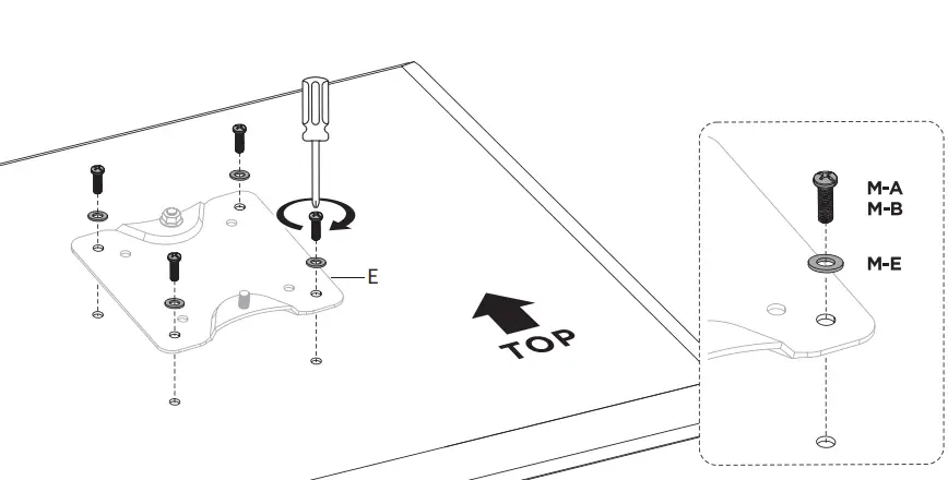
STEP 5 (Option A)
VESA Plate Only
Use Screws (M-A or M-B) along with M5 Washers (M-E) to attach VESA Plate (E) without the adapters to the monitor.
STEP 5 (Option B)
VESA Plate with Adapters
For TVs with VESA mounts at 200mm x 200mm or 200mm x 100mm, VESA Adapters (F, G) are required. Attach VESA Adapters (F,G) to VESA Plate (E) using M5x10mm Screws (S-A) and M5 Nuts (S-B). Tighten using Wrench (T-B) and a Phillips screwdriver.

VESA Plate with Adapters (Continued)
Use Screws (M-A through M-D) along with Washers (M-E, M-F) to secure VESA Plate (E) with the adapters to the back of your television. Make sure the “VIVO” logo is right side up.

For a curved television, Spacers (M-G) may be required.

STEP 6
To attach the TV to the stand, loosen the nut at the top of the VESA Plate (E) and slide into the slot on top of the mounting plate on Upper Pole (C). Secure the top of VESA Plate (E) to the stand by tightening the nut using Wrench (T-B). Secure the bottom of VESA Plate (E) using M6 Flange Nut (S-G) and wrench (T-B).


SKU: STAND-TV17
 |
Scan the QR code with your mobile device or follow the link for helpful videos and specifications related to this product. Instruction Manual https://vivo-us.com/products/stand-tv17 |
CUSTOMER SUPPORT
 Love your new VIVO setup and want to share?
Tag us in your photo! @vivo_us
GET IN TOUCH | Open Monday – Friday 7:00am – 7:00pm CST,
our dedicated support team can offer immediate assistance with rapid response times. If any parts are received damaged or defective, please contact us. We are happy to replace parts to ensure you have a fully functioning product.
 309-278-5303 309-278-5303 |
AVG. RESOLUTION TIME (within office hrs): 5M 4S |
 www.vivo-us.com www.vivo-us.comChat live with an agent! |
AVG. RESOLUTION TIME (within office hrs): < 15 M |
 [email protected] [email protected] |
AVG. RESPONSE TIME (within office hrs): 1HR 8M
|
| FOR MORE VIVO PRODUCTS, CHECK OUT OUR WEBSITE AT: www.vivo-us.com | |
