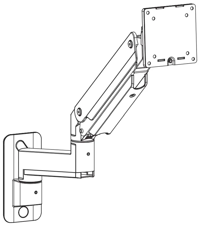
V I V O MOUNT-V101G1W Premium Aluminum Heavy Duty Monitor Arm
Contents
SAFETY PRECAUTION
 WARNING!
If you do not understand these directions, or if you have any doubts about the safety of the installation, please call a qualified technician. Check carefully to make sure there are no missing or defective parts. Improper installation may cause damage or serious injury. Do not use this product for any purpose that is not explicitly specified in this manual. Do not exceed weight capacity. We cannot be liable for damage or injury caused by improper mounting, incorrect assembly or inappropriate use.
 CAUTION!
DO NOT INSTALL INTO DRYWALL ALONE. VERIFY YOUR WALL CONSTRUCTION. USE WOOD STUDS TO MOUNT. We include mounting for brick and concrete walls. If unsure, please contact us at vivo-us. com, email at [email protected], or call us at 309-278-5303.
WARNING: CHOKING HAZARD
SMALL PARTS – NOT FOR CHILDREN UNDER 3 YEARS. ADULT SUPERVISION IS REQUIRED.
PACKAGE CONTENTS
- A (x1) Wall Bracket

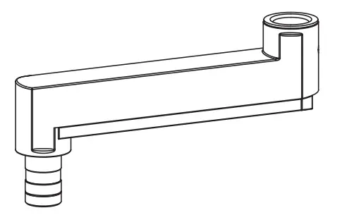
- B (x1) Lower Arm
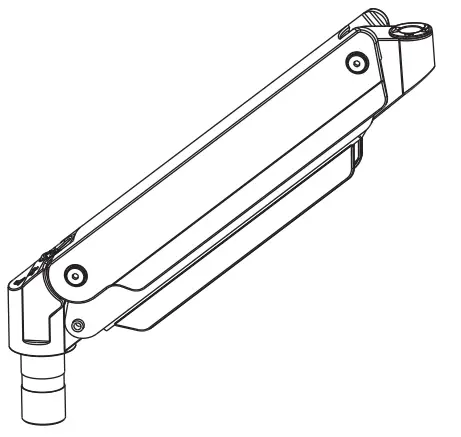
- C (x1) Gas Spring Arm
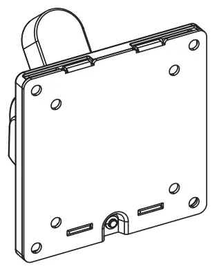
- D (x1) VESA Plate
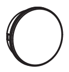
- E (x1) Round Screw Cap
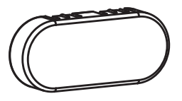
- F (x1) Oval Screw Cap
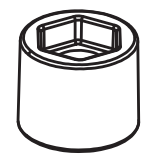
- S-A (x1) Keyed Spacer
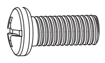
- S-B (x1) M8x25mm Screw

- M-A (x4) M4x12mm Screw

- M-B (x4) M5x12mm Screw
- M-C (x4) M5 Washer

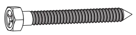
- W-A (x3) ST6.3x55mm Screw
- W-B (x3) Concrete Anchor

- W-C (x3) M6 Washer

- T-A (x1) 3mm Allen Wrench

- T-B (x1) 6mm Allen Wrench

TOOLS NEEDED
- Phillips Screwdriver

- Drill

- Stud Finder

- Ratchet

- Leve

NOTE: SOME HARDWARE INCLUDED MAY NOT BE USED
DO NOT EXCEED WEIGHT CAPACITY.
Failure to do so may result in serious injury.

ASSEMBLY STEPS
STEP 1 (Option A)
OPTION A: Wood Wall Installation
Use Wall Bracket (A) to mark drilling locations on the wall where a stud is located. Use of a level and stud finder is recommended. Using a 3/16” (4.5mm) bit, drill 2.2” (55mm) deep holes into marked locations. Secure Wall Bracket (A) to the wall using ST6.3×55 Screws (W-A) with M6 Washers (W-C) and a 10mm socket wrench. Insert Round Screw Cap (E) and Oval Screw Cap (F) into the mounting holes.

STEP 1 (Option B)
OPTION B: Concrete/Brick Wall Installation
Use Wall Bracket (A) to mark drilling locations on the wall. Use of a level is recommended. Using a 3/8” (10mm) bit, drill 2.4” (60mm) deep holes into marked locations. Insert Concrete Anchors (W-B) into predrilled holes. Secure Wall Bracket (A) to the wall using ST6.3×55 Screws (W-A) with M6 Washers (W-C) and a 10mm socket wrench. Insert Round Screw Cap (E) and Oval Screw Cap (F) into the mounting holes.

STEP 2
Assemble Lower Arm (B) and Gas Spring Arm (C) to Wall Bracket (A). Tighten set screws on Wall Bracket (A) and Lower Arm (B) using 3mm Allen Wrench (T-A).

STEP 3
Connect VESA Plate (D) to Gas Spring Arm (C) using Keyed Spacer (S-A), M8x25mm Screw (S-B), and 6mm Allen Wrench (T-B). Ensure that hexagon side of Keyed Spacer (S-A) is facing upward towards VESA Plate (D). Remove Thumbscrew (D1) from back of VESA Plate (D). Separate Front VESA Plate (D2) from Back VESA Plate (D3). Set aside

STEP 4
Connect Front VESA Plate (D2) to back of monitor using appropriate Screws (M-A, M-B), M5 Washers (M-C), and a Phillips Screwdriver.

STEP 5
To mount the monitor, begin by lining up the tabs on Front VESA Plate (D2) with the slots on Back VESA Plate (D3). Insert tabs into slots and re-install Thumbscrew (D1) into Back VESA Plate (D3) to secure.

STEP 6
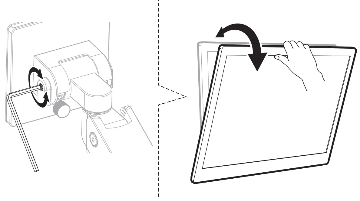
While holding Gas Spring Arm (C) in the horizontal position, adjust the gas spring tension using 6mm Allen Wrench (T-B).

How to adjust if…
ARM DROPS – If the arm drops, turn the adjustment screw counter clockwise until it holds the monitor in a horizontal position.

ARM RISES – If the arm raises up, turn the adjustment screw clockwise until it holds the monitor in a horizontal position.

CAUTION – To avoid damage to the monitor and mount, always keep the arm in a horizontal position while making adjustments.
STEP 7
Remove the cable management cover from Gas Spring Arm (C) using a Phillips screwdriver. Slide The cable management cover from Lower Arm (B) off. Route cables and reattach cable management covers.

STEP 8
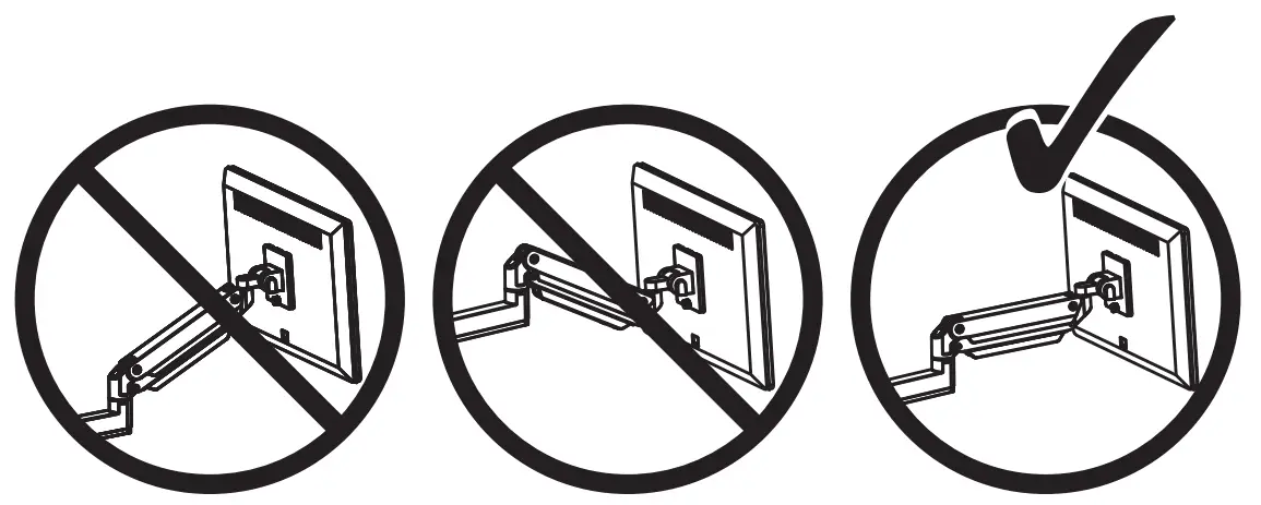
For safety, please do not extend the monitor behind the desk. This may cause instability and tip the desk over.

CUSTOMER SUPPORT
Love your new VIVO setup and want to share?
Tag us in your photo! @vivo_us
Open Monday – Friday 7:00am – 7:00pm CST,
our dedicated support team can offer immediate assistance with rapid response times. If any parts are received damaged or defective, please contact us. We are happy to replace parts to ensure you have a fully functioning product
 www.vivo-us.com
Chat live with an agent!
RESOLUTION TIME (within office hrs): < 15 M
 309-278-5303
AVG. RESOLUTION TIME (within office hrs): 5M 4S
 [email protected]
AVG. RESPONSE TIME (within office hrs): 1HR 8M
- 23% within < 15m
- 38% within < 30m
- 61% within < 1hr
- 83% within < 2hr
- 92% within < 3hr
FOR MORE VIVO PRODUCTS, CHECK OUT OUR WEBSITE AT: www.vivo-us.com
SKU: MOUNT-V101G1/W
Scan the QR code with your mobile device or follow the link for helpful videos and specifications related to this product.
https://vivo-us.com/products/mount-v101g1

GET IN TOUCH | Monday-Friday from 7:00am-7:00pm CST
[email protected]
www.vivo-us.com
309-278-53