![]()
INSTALLATION GUIDE
PUB2022JUN13

Contents
SYSTEM COMPONENTS
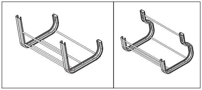
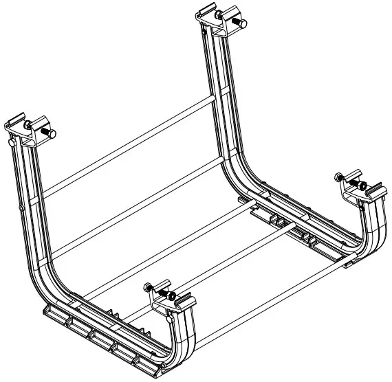
BALLAST Field BAY/North Bay: The Ballast Bay frame is made of a mill finish Aluminum. This roof mount is a modular design that allows for easily getting around roof obstructions and accommodating roof undulations. The Ballast Bays are created such that they nest within each other to optimize shipping logistics. North bay will be only used only on north row.
 OPTIONAL WIRE MANAGEMENT: The Ballast Bay frame runners will accept standard strut-strap wire management solutions, or standard strut nuts, available for purchase through your local electrical supply store.
NOTE: All conduit and wire ways should be grounded & bonded per the (NEC) National Electric Code.

CLAMP ASSEMBLY & SIDE BOLT: The Module Clamp is made of a mill finish Aluminum and engages the return flange underneath the module. A stainless-steel nut with an external tooth washer affixed to the end of a bolt is pre-assembled with the module clamps, which secures and electrically bonds the module. Side bolt is used to connect the clamp assembly to ballast bay.

ROOF PAD: The Roof Pad provides a protective interface between the Ballast Bay and roofing material. Please consult the roofing manufacturer to see whether it is required and to verify compatibility. Additionally, roof pads are required for unattached system installation in certain seismic areas. Refer appendix A for roof pad usage requirements. The Roof Pad snaps into the holes on the bottom side of the Ballast Bay.
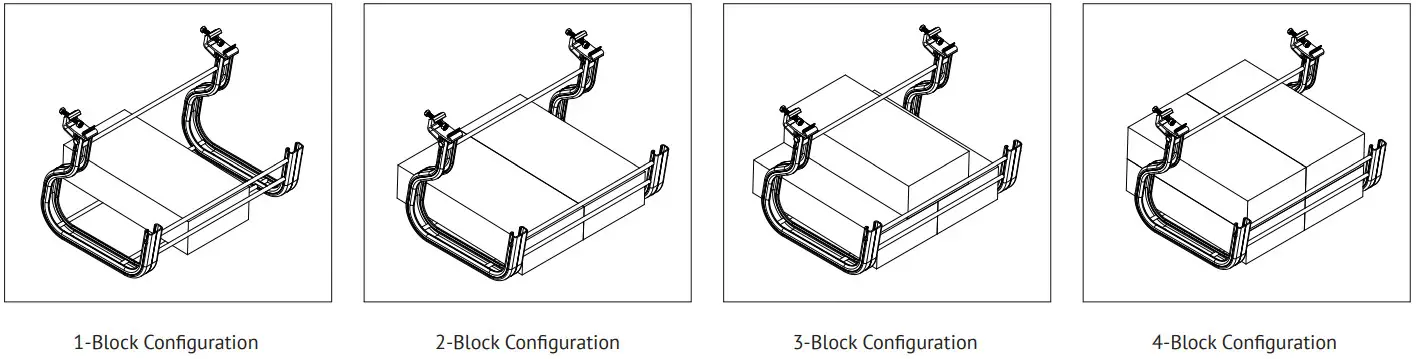
 BALLAST BLOCK: The RM field ballast bay can fit up to 3 and a half standard 4”x8”x16” solid concrete cap blocks (4 blocks on north ballast bay). See Page 5 “Complete Ballast Placement” page of this document for more information. Block weight can range from 26 – 38 lbs. The weight of the block will have a major impact on how many will be required for the project so be sure to verify your block weights before using the U-builder online tool.
NOTE:
- CMU should comply with ASM standard specification for concrete roof pavers designation (C1491 or C90).
- Oxidization of the star washer is possible in high salt environments but does not impact the integrity of bonding or strength.
- System labels for the RM10 and RM10 Evo systems are identical. Visually inspect the system components to distinguish between RM10 and RM10 Evo.
| S.no. | PART NUMBER | DESCRIPTION |
| 1 | 370010 | FIELD BAY |
| 2 | 370011 | NORTH ROW BAY |
| 3 | 370020 | CLAMP ASSEMBLY |
| 4 | 310760 | ROOF PAD |
TOOLS & SPECIFICATIONS
TECHNICAL SPECIFICATIONS:
Material Types: Mill finish aluminum for clampsand ballast bays (6105-T52, 6063-T5, 6061-T6 or 6005A-T61)
Hardware: Stainless Steel
Bonding and Grounding: UL2703 Listed Continuous Bonding Path.
TOOLS REQUIRED OR RECOMMENDED FOR LAYOUT, ATTACHMENTS & INSTALLATION:
- Drill (Do Not Use An Impact Driver)
- Shallow 1/2” Socket
- Torque Wrench
- Optional torque limiter (7 FT-LBS / 25 FT-LBS)
- Tape Measure
- Chalk Reel
- Optional Spacers (See Diagram – Page Right)
SAFETY:
All applicable OSHA safety guidelines should be observed when working on a PV installation job site. The installation and handling of PV solar modules, electrical installation and PV racking systems involves handling components with potentially sharp metal edges. Rules regarding the use of gloves and other personal protective equipment should be observed.
NOTE: The RM10 EVO mounting system may be used as a Ground Mount PV Module Mounting System provided that all relevant requirements from the National Electric Code ANSI/NFPA 70 and other jurisdictional codes are met.
See page 7 for guidelines regarding routine maintenance.
LAYOUT ASSISTANCE TOOL:
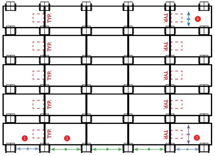
| Module Dimensions: | RM10 EVO | Module location: | Spacing Equations (in Inches): |
| Module Length (ML) = | 1 | Perimeter Column Spacing = | ML+(G/2)-30.37″ |
| Module Width (MW) = | 2 | Interior Column Spacing = | ML+G-19.25″ |
| Prefered module gap? (1/4″ – 1″ is permissible) |
3 | Field Row Spacing = | Fully install one panel in south row, cut spacer to N/S distance for all the bays except north row |
| 4 | North Row Spacing = | Fully install one panel in north row, cut spacer to N/S distance for north row |
|
| East/West Module Gap (G) = |
 The module J-Box in the column nearest the roof’s East or West edge must be oriented away from the edge of the roof in order to meet UL2703. Reference Appendix C.
SPACERS – OPTIONAL
| PERIMETER COLUMN SPACER | |
| COLUMN SPACER | |
| SOUTH ROW SPACER | |
| NORTH ROW SPACER |
ATTACH CLAMPS AND LOCATE ARRAY
 ATTACH CLAMP: Place the clamp on the bay, align the bottom hole on the clamp with the side hole on the bay, and install the side bolt.
Install the side bolt from the direction of the clearance hole.
TORQUE VALUE: 25 FT-LBS
 MARK ROOF WHERE ARRAY WILL START: Use chalk line to mark distances from roof edge ascalled out in construction documents.
 LOCATE ARRAY ON ROOF: Align Ballast Bays with previous chalk lines, using bay spacers as shown on Page 2 if desired.
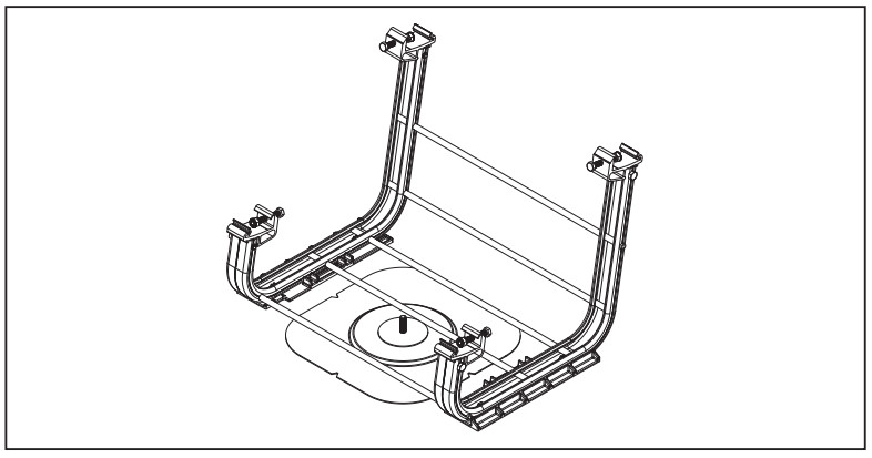
 PLACE SOME BALLAST IN 1ST FOUR BAYS TO RESIST THE BAY FROM ROTATING FOR FIRST MODULE INSTALLATION
NOTE: Refer to Appendix D & E for mid support and supplementary bays installation.
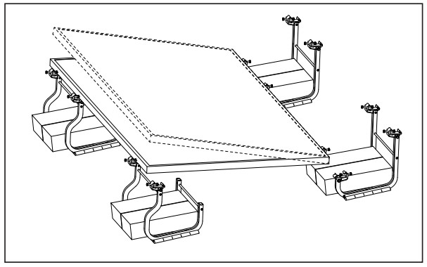 PLACE MODULE IN CLAMPS
 PLACE ANOTHER MODULE IN NEXT BAY CLAMP
COMPLETE ARRAY PLACEMENT
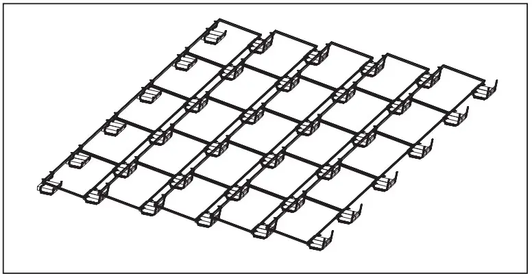 SEAT REMAINING MODULES IN CLAMPS: It is recommended to finish one row before beginning the next.
NOTE: 1/4″ – 1″ gap is required between modules for thermal expansion.
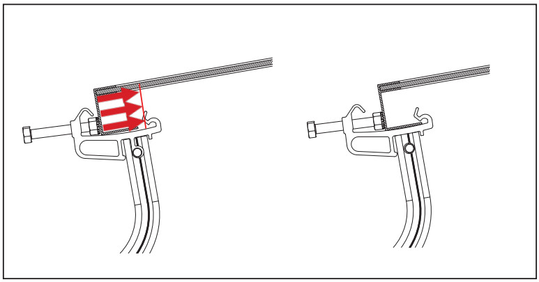 FULLY SEAT MODULE IN CLAMPS AND TIGHTEN BOLTS: A gentle tug on the bays will seat the module into the module Clamp. It is NOT recommended to use the bolt to seat the module.

 TIGHTEN BOLT AND CHECK CLAMP BOLT TORQUE IN SEQUENCE: It is recommended to tighten bolts one row at a time, working outward from the north or south edge of the array.
TORQUE VALUE: 7 FT-LBS
COMPLETE BALLASTED PLACEMENT: Place ballast as required. Deviations from block arrangements shown in this guide may cause shading. Site specific module loading and ballast calculations should be determined for each individual project in accordance with the U-Builder software. This system has been rated for the mechanical load provisions of UL2703. In addition, it has been designed and tested to comply with the more rigorous requirements of SEAOC PV1, PV2 and ASCE 7.
Note: To avoid wind events during installation, ensure bays are ballasted according to the design layout before module installation
COMPLETE BALLAST PLACEMENT
FIELD BAY:
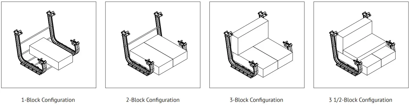
NORTH BAY:
SYSTEM GROUNDING

Although conformance with UL2703 was demonstrated without the use of oxide inhibitor material, it is recommended by Ilsco to provide an optimized bonding solution for their lay-in lug.
GROUNDING LUG MOUNTING DETAILS AS REQUIRED BY CODE & ENGINEER OF RECORD: Details are provided for both the WEEB and Ilsco products. The WEEBLug has a grounding symbol located on the lug assembly. The Ilsco lug has a green colored set screw for grounding indication purposes. One lug is recommended per continuous array, not to exceed 150ft X 150ft.
Unirac Roof Mount is intended to be used with PV arrays that have a system voltage less than or equal to 1500VDC. A min. 10 AWG, 105 degrees Celsius copper grounding conductor should be used to ground a 1500 VDC system, according to the (NEC) National Electric Code and the authority having jurisdiction. It is the installers responsibility to check codes, which may vary.
NOTE: The specific site installation must be conducted in accordance with the National Electric Code ANSI/NFPA 70 and any relevant local jurisdiction codes.
| Ground Lug | Bolt Size | Drift Size | Torque Value |
| WEEB Lug | 1/4″-20 | 17/64″ | 10 ft-lbs |
| lisco Lug | #10-32 | 7/32″ | 5 ft-lbs |
TEMPORARY GROUNDING & BONDING
TEMPORARY GROUNDING & BONDING PROCEDURE:
Periodic inspections should be conducted on the PV array to ensure there are no components damaged, corroded or connected loosely.
Replace the damaged or corroded components and re-tighten loose components according to the instructions.
If removing a module creates a discontinuity in the array which interrupts the ground path, a temporary bonding jumper must be used to ground the isolated array and ensure safety of the personnel and PV system.
NOTE: Removing a PV module from a system is not considered to be routine maintenance. This type of activity should only be performed by trained and qualified installers.
CAUTION: Module removal may disrupt the bonding path and could introduce the risk of electric shock. Additional steps may be required to maintain the bonding path.
Modules should only be removed by qualified persons in compliance with the instructions in this manual.
NOTE: In order to prevent corrosion induced by dissimilar metals, it is important to verify that the bare copper wire does not come into contact with aluminum.
These materials must be kept separate.
 APPROVED LUGS
WEEBLug UNIRAC PN 008002S
See product data sheet
Ilsco lay-in Lug Ilsco PN GBL-4DBT
See product data sheet
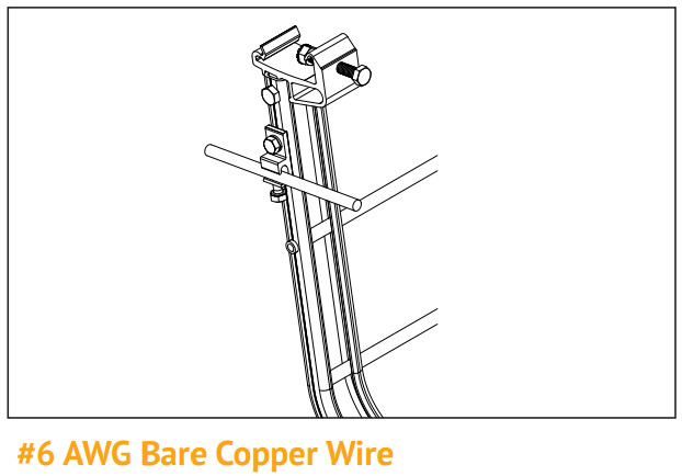 INSERT COPPER WIRE: Insert bare copper (#6 AWG) wire into each lug, providing a bonding jumper across the missing module location.
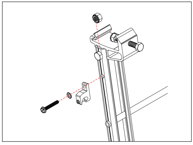 ATTACH LUGS: Use approved lug(s) to install on adjacent bays where the module is being removed.
 REMOVE MODULE & REVERSE THE OPERATION AFTER MAINTENANCE IS COMPLETE
NOTE: Removing a PV module from a system is not considered to be routine maintenance. This type of activity should only be performed by trained and qualified installers.
BONDING & GROUNDING
ELECTRICAL BONDING & GROUNDING TEST MODULES: This racking system may be used to ground and/or mount a PV module complying with UL 1703 only when the specific module has been evaluated for grounding and/or mounting in compliance with the included instructions. The modules selected for UL 2703 bonding & grounding testing were selected to represent the broadest range possible of modules on the market. The tests performed cover the following basic module parameters:
- Frame profile with vertical wall thickness ≥ 1.0mm, overall width ≤ 1.575”, return flange length ≥ 0.45”, and return flange thickness ≤ 2.1mm
- Basic single and double wall frame profile (some complex frame profiles could require further analysis to determine applicability)
- Clear and dark anodized aluminum frames
- The frame profile must not have any feature that might interfere with bonding devices that are integrated into the racking system
VERIFIED COMPATIBLE MODULES:
| Manufacturer | Module Model / Series |
| Astronergy / Chint | CHSM6610M (BF)+HV , AstroSemi CHSM72M-HC |
| AU Optronics (BenQ Solar) | PM Series |
| Auxin | AXN6M610T,MN6P6107,AXN6M6127 & AXN6P612T |
| Axitec | AC-XXXP/156-60, AC-XXXP/72S,AC-XXXM/725 |
| BenQ Solar | PhtaxP01 |
| Bwiet | (40mm) BVM6610(P/M) & BVM6612(P/M) |
| (35mm x 35mm) BVM6610(P/M) & BVM6612(P/M) |
|
| Canadian Solar | CS5A-M,CS6P-M,CS6P-P,C56X-P |
| CS3W-P/MS,CS3U-P (HE), C.53UMS, CS3K-P (HE), CS3K-MS (Black), CS3Y-MB-AG | |
| CS6K-MS (AUBlack) ,CS6K-14, C56K-P (HE), C56K, C56W-MB-AG | |
| CS3U-PB-AG,CS3U-MB-AG, C53K-PB-AG, CS3K-MB-AG, C53W-PB-AG, C53W-MB-AG | |
| CS6U-M,CS6U-P (HE), | |
| CS1K-MS,C.S1H-MS,C51U-MS, CS3W-P-PB-AG, CS3L-P | |
| ELPS C56P-MM, ELPS C56A-I4M | |
| Centrosolar America | C-Series & E-Series |
| CertainTeed | a rwp-OS, a M-02 & a M-03 |
| CSUN | C.SUN-72M,CSUN-72P |
| ET Solar | ET Module (40mm framed) ET AC Module (40mm framed) |
| Flex | FXS 60 |
| GCL | GCL-P6 & GCL-M6 |
| Hansol | UB-AN1. UD-AN1. TD-AN4, TD-AN 3 |
| Hanwha SolarOne | SolarOne HSL 60 SolarOne HSL 72 |
| Heliene | 72M, 72P, 60M & 60P, 72M-360 |
| HT-SAAE | H172-156M-C,HT72-156Me0-C, H172-156M,H172-156M(1), HT72-156P-C, H172-156P(/)-C |
| Hyundai Heavy Industries | TI, RI, KI, HI, MI & MG Series |
| JA Solar | JAP6 60,JAM6-60 /SI, JAM6(K)-60, JAP6(k)-72 /41313,JAP72SYY /ZZ, JAP6(k)-60 /41313,JAP6OSYY /ZZ, JAM6(k)-72 /ZZJAM72SYY /ZZ, Note: YY: 01, 02, 03,09,10 ZZ: SC, PR, BP, HiT, IB, MW |
| Jinko Solar | Standard,JKM P-60B 1KM M-60(3/BL/V/HB/FI/L/HL) 1KM PP-72(Plus) 1KM M-72(V/Plus) 1KM M-72HL4-(V/IV) 1KM PP-72-(L-V/V/EIL-V) 1KMxxxM-72HL4-V |
| Kyocera | KD-F Series |
| LG Electronics | LGooc(E1C/E1K/N1C/N1K/N2T/ N2W/Q1C/Q1K/S1C/S2W)-AS, LGx3ot(N1C/N1K/N2W/Q1C/ Q1K)-VS, LGookl2T-1S, LGxxx(N1K/N2T/N2W)-E6, LGxxx(A1C/M1C/M1K/N1Q)11K/ Q1C/Q1K/QAQQAK)-A6 LGxxxN1K-136 LGxxxN3K-V6 |
| LONGi | (40mm) LRS-72HBD LR6-60 & LR6-72 Series |
| (35mm) LR4-72HPH,LR4-72H1H, LR6-72, LR6-726K, LR6-72HV, LR6-72PE, LR6-72PB, LR6-72PH, LR6-72HPH,LR6-72H1H |
|
| Mission Solar | MSE Series |
| Panasonic | EVPVXXX(H/K/PK) |
| VBHN SA15/16/17(G/E)/18(E) | |
| VBHN KA01/03/04 | |
| Phono Solar Technology | Standard Modules |
| Q-Cells | QPEAK DUO (BLK) (ML) G10(+) |
| Q.PEAK DUO (BLK) ML-G9(+) | |
| Q.PEAK DUO L-G5(.1/.2/.3) | |
| Q.PEAK DUO L-67(.1/.2/.3/.4/.7) | |
| Q.PEAK DUO L-68(.1/.2/.3) | |
| QPEAK DUO L-G4.2 | |
| QPEAK DUO L- G6/L-G6.2/1-66.3 | |
| QPEAK DUO XL 69/G9.2/G9.3 |
- Unless otherwise noted, all modules listed above include all wattages and specific models within that series. Variable wattages are represented as “xxx”
- Items in parenthesis are those that may or may not be present in a compatible module’s model ID
- Slashes “/” between one or more items indicates that either of those items may be the one that is present in a module’s model ID
- Please see the RM10EVO UL2703 Test Report at Unirac.com to ensure the exact solar module selected is approved for use with RM10EVO
ELECTRICAL BONDING & GROUNDING TEST MODULES: This racking system may be used to ground and/or mount a PV module complying with UL 1703 only when the specific module has been evaluated for grounding and/or mounting in compliance with the included instructions. The modules selected for UL 2703 bonding & grounding testing were selected to represent the broadest range possible of modules on the market. The tests performed cover the following basic module parameters:
- Frame profile with vertical wall thickness ≥ 1.0mm, overall width ≤ 1.575”, return flange length ≥ 0.45”, and return flange thickness ≤ 2.1mm
- Basic single and double wall frame profile (some complex frame profiles could require further analysis to determine applicability)
- Clear and dark anodized aluminum frames
- The frame profile must not have any feature that might interfere with bonding devices that are integrated into the racking system
VERIFIED COMPATIBLE MODULES:
| Manufacturer | Module Model / Series |
| Q-Cells Cont. | Q.PEAK L G4.5 |
| Q.PEAK DUO XL – G11.3 BFG | |
| Q.PEAK DUO XL-G10.d / BFG | |
| Q.PLUS L-G4.2/TAA | |
| B.LINE PRO L-G4.1 | |
| Q.PLUS/PEAK/PRO L-G4.2 | |
| Q.PLUS/PEAK/PRO L-G4/L-G4.1 | |
| B.LINE PLUS/PRO L-G4.2 | |
| Q.PEAK DUO G5/G6/G7.x/G8 | |
| B.LINE PEAK DUO G7/G7.2/L-G7/L-G7.1/L-G7.2/L-G7.3 | |
| Q.PEAK DUO XL-G10.3/BFG Q.PEAK DUO XL-(G10.2/G10.3/G10.c/G10.d) |
|
| Renesola | All 60-cell modules |
| REC | Peak & Eco RECxxxAA (72/BLK/Pure) RECxxxNP (N-PEAK) (BLK) RECxxxNP2 (Black) RECxxxPE (BLK), TP2M RECxxxTP2(BLK2) TP2SM72, TP2S72,TP2S72 XV RECxxxTP3M (Black) RECxxxTP4 (Black) |
| Risen | RSM72-6 (P/M), RSM144-6 RSM110-8-XXXBMDG |
| S-Energy | SN P-10, M-10 & SN P-15 |
| Seraphime | SEG-6, SEG-E & SRP-6 Series |
| Sharp | ND-24CQCJ, ND-25CQCS, NDQ235F4, ND-F4Q300 |
| Silfab | SLA & SLG Series, SLA-X SIL-XXX-ML/NL/BL/HL/NT/HC |
| SolarWorld | Sunmodule Protect Sunmodule Plus |
| Solaria | Power XT-XXXC-BD, Power XT-XXXC-PD, Power XT-XXXR-BD, Power XT-XXXR-PD, Power XT-XXXR-AC |
| Sonali | SS-M-360 to 390 Series SS-M-440 to 460 Series SS-M-430 to 460 BiFacial Series |
| Sun Edison | F-Series & R-Series |
| Suniva | OPTIMUS & MV Series |
| SunPower (not compatible with Invisimount frame) | A-Series, X-Series, E-Series, M-Series, AC & Sig Black |
| Suntech | STP Series |
| Talesun Solar | TD6I72M, TD7G72M, TP572, TP596, TP654, TP660, TP672, HIPRO TP660, SMART TP660P |
| Tesla | TxxxH, TxxxS |
| Trina | DE15V(II), DEG19C.20, DE19, DEG15VC.20(II), DEG18MC, DE15H(II), DE15M(II), PA05, PD05, DD05, DE06, DD06 PD14, DD14A(II), DE14A(II), PE14, PD14,DE15 |
| URE | D7 (M/K) H7A, D7 (M/K) H8A |
| Vikram | Eldora, Solivo, Somera |
| Yingli | YGE60/72, YLM60/72, YLM-VG |
| ZN Shine | ZXM6-NHLDD144 |
- Unless otherwise noted, all modules listed above include all wattages and specific models within that series. Variable wattages are represented as “xxx”
- Items in parenthesis are those that may or may not be present in a compatible module’s model ID
- Slashes “/” between one or more items indicates that either of those items may be the one that is present in a module’s model ID
- Please see the RM10 EVO UL2703 Test Report at Unirac.com to ensure the exact solar module selected is approved for use with RM10 EVO
BALLAST BAY ROOF ATTACHMENT
STEP 1 – POSITION ROOF ATTACHMENT: Position Roof attachment under bay requiring attachment and install according to manufacturer installation instructions.
NOTE: Center roof attachment under ballast bay as close as possible.
 STEP 2 – ENGAGE FLANGE NUT: Place 3/8-16 serrated flange nut and 1″ OD washer on the anchor stud approximately halfway down, nut serrations facing up.
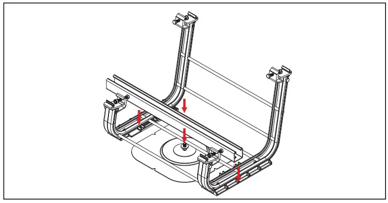
STEP 3 PLACE UNISTRUT: Place 24” Unistrut across RM bay with the anchor stud though a slot.
STEP 4 – SECURE UNISTRUT TO BAY: Place strut nuts inside RM channels under Unistrut, and secure Unistrut with 3/8-16 x 3/4” bolt and 1″ OD washer to 30 ft-lb.
TORQUE VALUE: 30FT-LBS
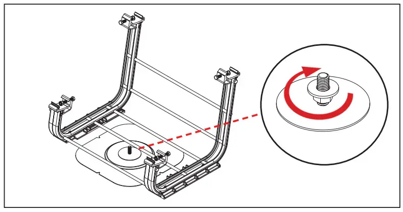
STEP 5 – SECURE UNISTRUT TO U-ANCHOR:
Tighten nut that was placed on roof attachment stud in step 2 until making contact with the underside of the Unistrut. Then place another 3/816 serrated flange nut and 1″ OD washer on the stud, serrations facing down and tighten to 30 ft-lb.
TORQUE VALUE: 30FT-LBS
BALLAST BAY RM FLASHLOC
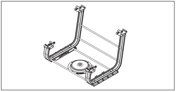
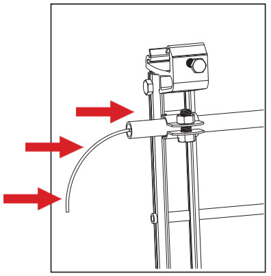
STEP 1 – POSITION FLASHLOC RM: Position Flashloc RM under bay requiring attachment and install according to Unirac installation guide.
NOTE: Center roof attachment under ballast bay as close as possible and remove the tube that interferes with attachment using a tube cutter
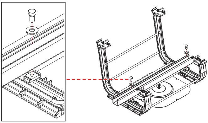
 STEP 2 – REMOVE BOLT AND WASHER: Remove the bolt and washer from Flashloc RM
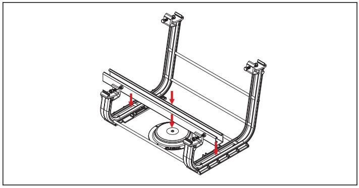 STEP 3 PLACE UNISTRUT: Place 24” Unistrut across RM bay.
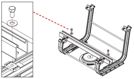 STEP 4 – SECURE UNISTRUT TO BAY: Place strut nuts inside RM channels under Unistrut, and secure Unistrut with 3/8-16 x 3/4” bolt and 1″ OD washer to 30 ft-lb.
TORQUE VALUE: 30FT-LBS
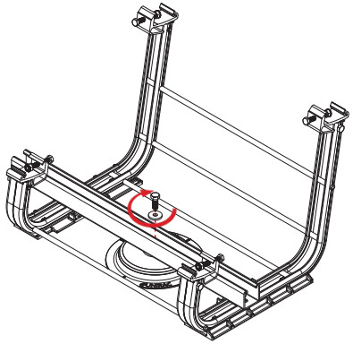
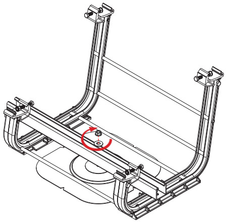
STEP 5 – SECURE UNISTRUT TO FLASHLOC RM:
Tighten bolt and washer removed in step 2.
TORQUE VALUE: 30FT-LBS
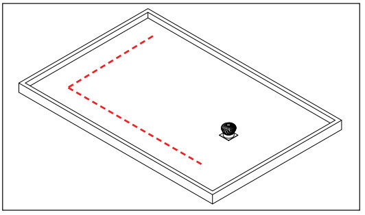
ROOF PAD INSTALLATION

ROOF PAD NOTE:
Roof pads are required for unattached system installation in certain seismic areas or are included upon request, following below guidelines:
- Roof pads are always applied 2 per bay (one on each ski).
- When installing minimum roof pads for friction (at a 1:4 ratio), apply 2 roof pads to every 4th bay, staggering the offset between rows.
- Alternatively, install 2 roof pads to every other bay in a row of bays, then skip a row, and do it again.
- Skip any bays that have mechanical roof attachments (i.e., Anchor Products, OMG, or RM Flashloc attachments).
Compatibility with roofing surfaces
Unirac has thoroughly tested the material of the RM10 Roof Pad. An industry leader in the evaluation of the compatibility of plastic and rubber formulations tested its interaction with numerous roofing types at a range of pressures and high temperatures. No change in surface or visible exchange between raw materials was observed. Here are minimum ratios by main roof types for applications where friction coefficients must be met:
| EPDM | 1:1 | Pads on each bay |
| TPO | 1:4 | Pads on 1of every 4 bays |
| PVC | 1:4 | Pads on 1of every 4 bays |
| Mineral cap | N/A | No pads required |
Further information
Consult our YouTube channel regularly for new Tips & Tricks (https://www.youtube.com/user/uniracsolar1).
BONDING & GROUNDING ELECTRICAL DIAGRAM

| Fault Current Ground Path | |
| Ground Lug | |
| Grounding clamp & bolt | |
| Min. 10 AWG Cooper Wire |
Module Frame
Module Bay w/ Grounding Clamps
FIRE & MLT TESTING
SYSTEM LEVEL FIRE CLASSIFICATION: The system fire class rating is only valid when the installation is conducted in accordance with the assembly instructions contained
in this manual. RM Roof Mount has been classified to the system level fire portion of UL2703. It has achieved Class A performance for low sloped roofs when used in conjunction with the following module constructions:
Type 1
Type 2
Type 3 with an aluminum frame
Type 19
Type 22
Type 25
Type 29
Type 30
In order to maintain the system Class A fire performance rating the following criteria must be met:
- Modules are installed so that the junction box is away from the array perimeter. This can be ignored if the junction boxes are not near the edge of the module
- Minimum and maximum roof slopes are restricted through the system design and layout rules. The fire classification rating is only valid on roof pitches less than 2:12 (slopes < 2 inches per foot, or 9.5 degrees.
- Rack mounting system is to be installed over a fire resistant roof covering rated for the application
MECHANICAL LOAD TEST QUALIFICATION
The Unirac RM system has been tested to the mechanical load provisions of UL2703 and covers the following basic parameters:
- PV module may have reduced load rating, independent of the RM10 EVO rating. please consult the PV module manufacturer’s installation guide for more information.
- Load rating may vary based on PV module area. Please Contact Unirac for more information
- Frame thickness greater than or equal to 1.0mm
- Basic single and double wall frame profiles
| Module Manufacturer | Model / Series | Area [sqft] | Design Load [PSF] |
| Jinko Solar | JKM M-72HL4-V | 27.76 | 15.3 up / 32 down |
| SunPower | SPR-E20-327 / E-Series | 17.54 | 15.0 up / 50 down |
| Canadian Solar | CS3W-PB-AG | 24.05 | 17.0 up / 20.6 down |
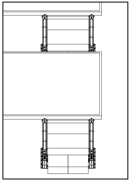
MID SPAN SUPPORT INSTALLATION

MID SPAN SUPPORT INSTALLATION
Use north bays for north rows, field bays for south rows and use field skis for field rows as Mid supports as shown in above figure. Place all the bays and mid supports first and then start installing the modules.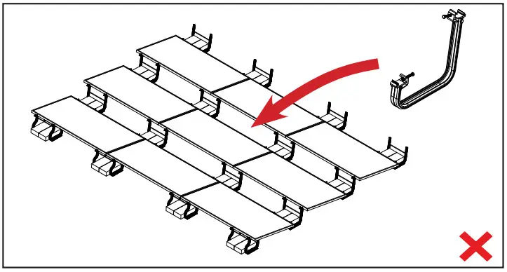
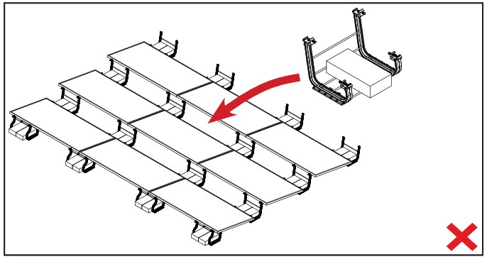
SUPPLEMENTARY BAYS INSTALLATION
 SUPPLEMENTARY INSTALLATION
In few cases tool / U-builder blocks per bay layout shows supplementary bays (additional bays) within the module to accommodate additional ballast required. Place all the bays, supplementary bays and mid supports first and then start installing the modules.

![]()