![]() Instruction Manual
Instruction Manual
Contents
TREND IQ5 I/O Modules Control Systems Launches
Product Information
Specifications:
- Model: IQ5-IO
- Installation Instructions Version: TG201484 Issue 1, 17-Oct-2023
- HOA variants: 67.5 mm (2.66), 119.5 mm (4.70), 131 mm (5.16)
- Non-HOA variants: 105 mm (4.13), 109.5 mm (4.31), 54.5 mm (2.15), 60 mm (2.36)
- Altitude: Up to 4000 m (13124 ft)
- IP Rating: IP20
- UL Rating: UL60730 listed open energy management equipment
Product Usage Instructions
Box Contents
Ensure that the following items are included in the box:
- IQ5-IO I/O Module
StoringWhen storing the IQ5-IO module, make sure to:
- Maintain a humidity level of 95%RH
- Prevent condensation on or within the unit
Installation
Follow these steps to install the IQ5-IO module:
- Ensure that the installation complies with local electrical safety practices.
- For HOA modules, ensure the dimensions are as follows: 67.5 mm (2.66), 119.5 mm (4.70), 131 mm (5.16).
- Mount the IQ5-IO module on a DIN Rail using the provided end stop.
- The maximum distance between IO modules should be 300 meters to maintain communication even if two sequential IO modules lose power.
- Connect the PSU (Power Supply Unit) to the IQ5-IO module.
FAQ
Q: Can I install the IQ5-IO module outdoors?
A: No, the IQ5-IO module is suitable for indoor use only. Q: What is the maximum distance between IO modules?
A: The maximum distance is 300 meters to maintain communication even if two sequential IO modules lose power. Q: What is the UL rating of the IQ5-IO module?
A: The IQ5-IO module is UL60730 listed as open energy management equipment.
Important: Retain these instructions
These instructions shall be used by trained service personnel only. If the equipment is used in a manner not specified by these instructions, the protection provided by the equipment may be impaired.
https://partners.trendcontrols.com

BOX CONTENTS

- 16UIO
- 8UIO-105
- 16DI
- 8DO
- 8DO-HOA
STORING

Note:
For temperatures below 0°C (32°F) special care must be taken that there is no condensation on or within the unit.
INSTALLATION
Labels used on IQ5-IO modules

- It is recommended that the installation should comply with the local electrical safety installation practices (e.g. HSE Memorandum of Guidance on Electricity at Work Regulations 1989, USA National Electric Code).
CAUTION:
- Do Not Inter-connect the Outputs of Different Class 2 Circuits.
- To Reduce the Risk of Electric Shock – Do not connect to a circuit operating at more than 150 volts to ground.
Dimensions

Mounting Requirements
This device is suitable for indoor use only.


Note:
For temperatures below 0°C (32°F) special care must be taken that there is no condensation on or within the unit.
- Protection IP20
- Altitude ≤4000 m (13124 ft)
- Pollution degree 2 (only non-conducting pollution occurs)
Must be installed in an enclosure rated to at least IP20 (or equivalent) or mounted outside normal reach (e.g. in a plenum).

The unit is UL rated as ‘UL60730 listed open energy management equipment’.


Connect I/O Bus – Overview
Depending on the controller licence, up to 300 I/O channels are supported.

It is recommended that the maximum distance between IO modules is *300 meters so that communication between the controller and the IO modules will be maintained even if two sequential IO modules lose power. If more than 2 sequential modules loose power, the communication between the controller and IO modules downstream of the offline IO modules may be compromised. Bus voltage must not be allowed to drop below 19V at full load. See step 4 to determine power requirements.
Cable Length
- Lon cable TP/1/0/16/HF/200 (Belden 8471) – up to 300 m (1000 ft) between modules.
Check Power Requirements

The IQ5 controller can supply 24 Vac/dc to adjacent or remote I/O modules via the power line of the T1L I/O bus. Check that the available current from the controller supply is sufficient to drive the required number and type of I/O modules.

- If more power is required than can be provided by the controller, one or more additional external power supply units must be installed on the I/O bus (see step 9). Note: UL regulations do not allow power from different supplies.
- Note: It may also be necessary to split the I/O bus supply to avoid exceeding the maximum 2 A flowing through any IQ5-IO module.

Switch Off Controller

Mount the Module(s)
Set the rear mounting clips to the correct position

I/O Bus – Install Wiring Adapters (if required)
Unclip and remove the cover from each wiring adapter:
Note:
The cover can be refi tted to either side of the adapter, depending on whether it is located to the left or right hand side of a module (see step 10).

Fit an adapter to the left or right of each module as required, ensuring the correct position of the power and data terminals:

I/O Bus – Fit Interconnecting Cables (if required)
- Plug-in connectors with screw terminals
- Terminal size: 0.2 to 2.5 mm2 (26 to 14 AWG). Terminal torque: 0.5 Nm (4.5 lbf-in) maximum.
Earth / ground Connections
For cables <1 m (39”) and where modules are in the same secondary enclosure, ground terminals may be linked:
For cables >1 m (39”) or where modules are in different secondary enclosures, ground terminals must be separated:

CAUTION:
The 0V terminal AND ground (earth) terminal MUST be connected as shown. Failure to observe correct wiring of I/O modules may result in damage to devices on the I/O bus in the event of a transient high voltage occurring at one of the I/O ports.
I/O Bus – Connect Additional PSUs (if required)
Example:
Group of three modules powered from the controller and two groups of three modules powered from external PSUs:

- IMPORTANT: Not permitted for UL-compliant installations.
- CAUTION: The maximum current flowing through the I/O bus supply on any module must not exceed 2 A.
CAUTION:
The 0V terminal AND ground (earth) terminal MUST be connected as shown. Failure to observe correct wiring of I/O modules may result in damage to devices on the I/O bus in the event of a transient high voltage occurring at one of the I/O ports. The 24 V line of each PSU (including the controller) must be isolated from each other.
I/O Bus – Fit Wiring Adapter Covers (where required)

I/O Bus – Fit End Cover to Last Module
Note:
A cover is supplied with the IQ5 controller. Spare covers are also available to order (e.g. IQ5-IO-END-10). The cover may be fitted to either side of the module as needed.

Remove Module Terminal Covers

Connect Inputs/Outputs – Overview
- Plug-in connectors with screw terminals (as supplied)

- Plugin connectors with push-fit terminals (optional)

| Terminal Type | Conductor Size | Stripping Length | Maximum Torque |
| Screw | IEC: 0.2 to 2.5 mm2UL: 26 to 12 AWG | 6-7 mm | 0.5 Nm (4.5 lbf-in) |
| Push-fit | IEC: 0.2 to 2.5 mm2UL: 26 to 14 AWG | 9 mm | n/a |
Recommended cable:
- DI and UIO: TP/1/1/22/HF/200 (Belden 8761);
Note: For UL rating use 22 to 14 AWG – Cu only cable.
Screened cable is optional and not generally required unless the cable passes through electrically noisy environments. Where it is used the screen must be connected to the local panel/enclosure ground (e.g. using an Auxiliary Terminal Block – see step 14) and left unterminated at the far end.
| Module | Type | Go to step… |
| 16UIO 8UIO | Universal Input/Output | 15 |
| 16DI | Digital Input | 17 |
| 8DO 8DO/HOA | Digital Output | 16 |
Fit Optional Auxiliary Terminal Blocks (if required)
The optional AUX-TRM-16 terminal block has two common groups of 8 push-fit terminals, a maximum of 12 A. It can be clipped onto the IQ5-IO modules and used for distributing 24 Vdc power (on UIO modules) or for connecting cable screens.

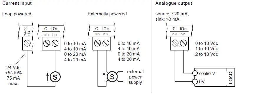
Connect Universal Inputs/Outputs (..UIO modules only)

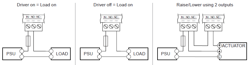
Connect Digital/Relay Outputs (..DO modules only)

- Contact Rating (voltage):
- All channels: 19 to 250 Vac; 12 to 29 Vdc.
- Channels 1-4, 6-9: 5A resistive; 3A inductive.
- Channel 5: 10A resistive; 6A inductive.
- Maximum Inrush
- 7. 5 A (channels 1-4, 6-9);
- Minimum Load 10 mA (all channels).
Ensure that external circuits are suitably protected against fault currents that would exceed the ratings for the switching circuits provided in this product.
Caution:
Mains and low voltage must not be mixed within relay block 1 (ch.1-4) or relay block 2 (ch5-8). If both mains and low voltages are to be switched, connect mains to block 1 and low voltage to block 2, or vice versa. If switching mains, all relays must switch the same phase and polarity. An arc suppression circuit (RC) is recommended for inductive loads (see TG200208). UL rating applies up to 240 Vac (120 VA) maximum.
Example wiring
Fit optional jumper to ‘IN’ terminals (if required)

Note:
If you don’t want one of the relays to be linked, you can break off the corresponding pin using needle nose pliers.

Connect Digital Inputs (..DI modules only)
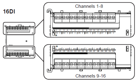
Connecting to volt-free, open collector or logic devices

Refit Terminal Covers
Note:
Spare covers are available to order (e.g. IQ5-TCVR-105-10)
Configure IQ5 Controller and I/O Modules
FIELD MAINTENANCE
The IQ5-IO modules require no routine maintenance.
WARNING:
Contains no serviceable parts. Do not attempt to open the unit. Failure to comply may cause damage to the unit.
REMOVING MODULE FROM DIN RAIL
- Isolate Power (including IO supplies)Warning: Hazardous voltages may be present on I/O terminals. Isolate before touching.
- Unplug Wired I/O Connectors
- Unclip Module from DIN Rail
DISPOSAL
WEEE Directive:
- At the end of their useful life the packaging and product should be disposed of by a suitable recycling centre.
- Do not dispose of with normal household waste. Do not burn.
CHINA HAZARDOUS SUBSTANCES TABLE
| Component Name | Hazardous Substances | |||||
| Lead (Pb) | Mercury (Hg) | Cadmium (Cd) | Chromium VI Compounds (Cr6+) |
Polybrominated Biphenyls (PBB) |
Polybrominated biphenyl Ethers (PBDE) |
|
| Cables | X | 0 | X | 0 | 0 | 0 |
| PCB Assembly | X | 0 | X | 0 | 0 | 0 |
| Connectors | x | 0 | X | 0 | 0 | 0 |
| Enclosures (Plastic) | 0 | 0 | 0 | 0 | 0 | 0 |
| Enclosures (Metal) | x | 0 | 0 | 0 | 0 | 0 |
| This table is prepared in accordance with the provisions of SJ/T 11364. | ||||||
| Indicates that said hazardous substance contained in all of the homogeneous materials for this part is below the limit requirement of GB/T 26572. | ||||||
| Indicates that said hazardous substance contained in all of the homogeneous materials for this part is above the limit requirement of GB/T 26572. | ||||||
| All other components, not listed in the table, do not contain restricted substances above the threshold level | ||||||
Please send any comments about this or any other Trend technical publication to [email protected].
© 2023 Honeywell Products and Solutions SARL, Connected Building Division. All rights reserved. Manufactured for and on behalf of the Connected Building Division of Honeywell Products and Solutions SARL, Z.A. La Pièce, 16, 1180 Rolle, Switzerland by its Authorized Representative, Trend Control Systems Limited. Trend Control Systems Limited reserves the right to revise this publication from time to time and make changes to the content hereof without obligation to notify any person of such revisions or changes.
Trend Control Systems Limited
St. Mark’s Court, North Street, Horsham, West Sussex, RH12 1BW, UK.
Tel: +44 (0)1403 211888,
www.trendcontrols.com.
Read more: 