TOPPING TP129 D70 Pro SABRE Digital an Analog Converter User Manual

Contents
Contents list
TP129: x 1
Remote control: x 1
USB cable: x 1
AC cable: x 1
Bluetooth antenna: x 1
User manual: x 1
Warranty card: x 1
Note: You can download the driver and user manual on https://www.topping.audio/
Part names
Attribute
| Measured | 22.2cm x 17.6cm x 4.8cm (Include protruding parts) |
| Weigh | 1050g |
| Power input | 100-240VAC 50Hz/60Hz |
| Signal input | USB/BT/OPT/COAX/AES |
| Line Out output | XLR/RCA |
| Other interfaces | 12V Trigger In(3.5mm jack) 12V Trigger Out(3.5mm jack) |
| Display | 2inch LCD |
| Bluetooth range | >10 M |
Attribute
| USB IN | PCM 44.1kHz-768kHz/16bit-32bit DSD DSD64-DSD512 (Native) , DSD64-DSD256 (DoP) |
| COAX/OPT/AES IN | PCM 44.1kHz-192kHz/16bit-24bit DSD DSD64 (DoP |
| BT IN | AAC/SBC/APTX/APTX HD/APTX-Adaptive/LDAC |
Front panel

Rear panel


- Screen
- Remote control receiver
- Menu Enter/exit the setup menu or return to the upper menu
- Input channel switching
- Home page switching
- Volume knob & User-defined button Rotate the knob: Adjust the volume. Press the knob: User-defined function. Please set at [Setup Menu- Advanced-Button].
- Right channel balanced XLR output
- Left channel balanced XLR output
- Left channel single-ended RCA output
- Right channel single-ended RCA output
- Coaxial SPDIF input
- Optical SPDIF input
- Bluetooth input
- USB input
- AES input
- 12V Trigger IN/OUT The 12V Trigger IN/OUT allows the TP129 to be activated by other devices or to activate other devices via a 3.5mm mini phone plug cable. The connected device must be equipped with a 12V Trigger In/Out to use this feature. *Before using the Trigger IN function, you need to set the [Setup Menu- On/Off trigger] to “12V”
- Power input(AC 100-240V 50Hz/60Hz)
- Power switch
Display
There are three types of home page displays: Normal, VU and FFT, which can be switched by pressing the  button on the front panel or can be set in the menu [Setup Menu – Display – Home].
The home page display in DAC mode and PRE mode will be slightly different. [Setup menu-Advanced-DAC mode]
PRE mode: Volume is adjustable.
DAC mode: TP129 keeps the maximum volume output and the volume is not adjustable
PRE mode

DAC mode

*VU Meter, FFT and Level meter monitor or reflect TP129’s output level under the current input.
TP129 has 3 output modes: SE, BAL and ALL [Setup menu- Output select]. In SE output mode, the VU Meter, FFT and Level meter reflect RCA output level. In BAL/ALL mode, the output level of XLR is reflected.
*VU Meter, FFT and Level meter do not support DSD512.
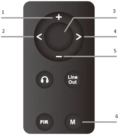
Remote control

 See “4. On/Off trigger” in the “Setup Menu”, below.
See “1-2 Brightness” in the “Setup Menu”, below
Connection
Connect to the input source

Support USB, Coaxial, Optical, Bluetooth, AES input.
Connect to amplifier or active speakers
Use XLR or RCA cables to connect to the amplifier or active speakers. In order to avoid damage to your devices, please turn off the amplifier or active speakers before you connect them to TP129.
Operation
Power on & off / standby operation
- Power on & off: Press the power switch on the rear panel to turn TP129 on or off.
- Standby setting: When it is working, press and hold the knob on the front panel to enter standby state and press to exit standby state when it is in standby. Or you can directly press the standby button
 on remote control to enter or exit standby state.
Volume setting
- The enter and exit of mute state: Press the mute button
 on the remote control to set mute, press the mute button again or adjust the volume to exit mute state.
 - Volume adjusting: You can directly turn the volume knob or press the
 and
and  button on the remote control to adjust the volume. Note that long pressing the and button on the remote control will quickly adjust the volume, so please be careful in order to protect your hearing.
Note: Volume is fixed to 0dB in DAC mode and volume adjusting is invalid in this mode. [Setup menu-Advanced-DAC mode].
Input channel switching
Press the touch button on the front panel or the or
or  button on the remote control to switch the input in cycle.
Output channel switching
Press the button on the remote control to switch the output in cycle. You could also switch the output channel by pressing the knob, but note that you need to set [Setup Menu-Advanced-Button] to “Output select”. (Default)
Setup Menu
Enter menu and change settings
The knob on the front panel
Press![]() : Enter/exit the setup menu or return to the upper menu
: Enter/exit the setup menu or return to the upper menu
Press : Exit the setup menu
Rotate the knob: Enter the previous/next setting item
Press the knob: Change the setting/OK/Enter the lower menu
The remote control
- Enter the previous setting item
- Change the setting
- Enter the setup menu/ OK
- Change the setting
- Enter the next setting item
- Enter/exit the setup menu or return to the upper menu
Setup menu

Display
Home
Home page display
Normal (Default), VU, FFT
Brightness
Low, Medium (Default), High, Auto Auto has the same brightness as Medium. The differences lie in when there is no operation after 30 seconds under Auto mode, the screen will be automatically turned off, only displays the current input. You can press any button to light up the screen

Classic VU 0dB
Set 0dB reference voltage for VU meter, such as if set to +4dBu, when the pointer swings to 0dB, the current output level of the TP129 is
+4dBu.
+4dBu(Default), +10dBu
Level meter
All on (Default), Normal page, FFT page, All of
Input select
USB (Default), OPT, COAX, AES, BT
Output mode
SE: only RCA output
BAL: only XLR output
ALL (Default): RCA and XLR output simultaneously
On/Off trigger
Signal Default): Trigger turn on or standby based on input signal. If the current input is not connected or input signal is invalid in 1 minute, it will automatically enter the standby state. Once having detected valid signal, it will automatically return to working state.
12V: Trigger turn on or standby based on 12V signal. When TP129’s Trigger In is connected to another device’s 12V Trigger Out, TP129’s power on/standby can be controlled through this device. The TP129 will remain in standby state until Trigger In detects the signal change from 0V to 12V. When changing back to 0V, the TP129 will return to standby state. Off: Disabled this function.
PCM filter
F-1: Minimum Phase Default)
F-2: Linear Phase Anodizing
F-3: Linear Phase Fast Roll-off
F-4: Linear Phase Slow Roll-off
F-5: Minimum Phase Fast Roll-off
F-6: Minimum Phase Slow Roll-off
F-7: Minimum Phase Slow Roll-off Low Dispersion
Advanced
Channel balance
Setting range: C (Balance), L+0.5~9.5dB or R+0.5~9.5dB. (Default: C) *When using the knob, press the knob to enter the setting, rotate the knob to set the parameter, and press the knob again to exit the setting.
Sound mode
Off (Default), Valve, Transistor
Output level
Maximum output level at 0dBFS
4V(Default),5V
DAC mode
PRE (Default): Volume is adjustable.
DAC: Keep the maximum volume output and the volume is not adjustable.
Bluetooth
DAC: Keep the maximum volume output and the volume is not adjustable . Enable (Default), Disable
Remote
Enable (Default), Disable
Button
Customize the function of the press knob. Output select (Default), Home select, Brightness select, Dim the screen, Filter select, Mute, Input select
Bandwidth
Customized settings from 4 to 15, the larger the number is, the stronger the range to adapt to jitter, and the smaller the number, the better the performance. (default: 5) *When using the knob, press the knob to enter the setting, rotate the knob to set the parameter, and press the knob again to exit the setting.
Language
Scan the QR code on the right for the video.

Factory rese
Select factory reset will have a pop-up prompt, select Yes/No (selected for blue), then press the middle button of the remote or the front panel knob to confirm the selection.

Trouble shooting
| Phenomenon | Cause | Solution |
| No sound | Wrong input was selected | Select the correct input |
| Wrong output was selected | Select the correct output | |
| Incorrect cable connections | Check and reconnect | |
| Sound is muted | Turn up the audio | |
| Audio source no output | Adjust or check it | |
| USB did not recognize | USB cable did not connected properly | Check or change the cable |
| PC’s USB port damaged | Change another port | |
| The PC does not work | Check or try with another PC | |
| The OTG function of the phone is not enabled | Enable OTG function | |
| USB input, no sound | Too low volume on PC | Adjust volume |
| Tp129 is not selected as the output device on the PC | Set the TP129 as the default output device | |
| Cannot pair TP129 Bluetooth | Bluetooth is disabled on TP129 | Enable Bluetooth in the setup menu [Setup menu-Advanced-Bluetooth] |
| TP129 is already connected to other Bluetooth device | Let TP129 enter pairing mode first. | |
| Weak signal due to long distance | Take the device closer to TP129 and connect again | |
| Bluetooth input, no sound | Too low volume on phone | Adjust volume |
| DAC abnormal | DAC abnormal | Do not connect the TP129 to any other devices, unplug and re-plug the power cable and reboot the unit. |
| DIR abnormal | DIR abnormal | |
| PN voltage abnormal/ low /high | PN voltage abnormal/low /high | |
| 5V voltage abnormal/ low /high | 5V voltage abnormal/low /high | |
| Ak4377 abnormal | AK4377 abnormal | |
| If you still have problems or questions, please contact us([email protected]) | ||
FCC WARNING
This device complies with part 15 of the FCC Rules. Operation is subject to the following two conditions: (1) this device may not cause harmful interference, and (2) this device must accept any interference received, including interference that may cause undesired operation. Any changes or modifications not expressly approved by the party responsible for compliance could void the user’s authority to operate the equipment.
NOTE: This equipment has been tested and found to comply with the limits for a Class B digital device, pursuant to Part 15 of the FCC Rules. These limits are designed to provide reasonable protection against harmful interference in a residential installation. This equipment generates, uses and can radiate radio frequency energy and, if not installed and used in accordance with the instructions, may cause harmful interference to radio communications. However, there is no guarantee that interference will not occur in a particular installation. If this equipment does cause harmful interference to radio or television reception, which can be determined by turning the equipment off and on, the user is encouraged to try to correct the interference by one or more of the following measures:
- Reorient or relocate the receiving antenna.
- Increase the separation between the equipment and receiver.
- Connect the equipment into an outlet on a circuit different from that to which the receiver is connected.
- Consult the dealer or an experienced radio/TV technician for help.
To maintain compliance with FCC’s RF Exposure guidelines, This equipment should be installed and operated with minimum distance between 20cm the radiator your body: Use only the supplied antenna.
![]()