![]()
MODEL RTA-913D
ASSEMBLY INSTRUCTIONS
Thank you for purchasing our product.

Contents
RTA-913D Home Office Workstation with Storage

- Please read carefully the assembly instructions before the installation.

- Do not discard this manual or any of the packaging material until the unit has been completely assembled.

- Might require two people.

- We have added QR Codes to some steps for your assistance. If a QR code is provided on a step, scan it to view the assembly video online.
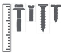
MAIN PARTS LIST

LIST OF HARDWARE, SCREWS AND FITTINGS
| PART | QTY | ITEM | |
| A | 10 | M6x30 Wooden dowels |
 |
| B | 14 | M5x31 Bolts |
 |
| C | 14 | M12x9 Cam locks |
 |
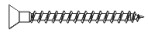
| D | 8 | ST3.5×40 (Flanged head) |
 |
| E | 4 | ST3.5×40 (Flat head) |
 |
| F | 4 | ST3.5×25 |  |
| G | 16 | ST4x12 |  |
| H | 16 | ST3x12 |  |
| I | 14 | 15mm plastic adhesive covers |  |
| J | 40 | M4x23 nails |
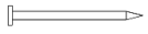 |
| K | 6 | 12x12x6mm Nail-in glide stud |
 |
| L | 2 | 128mm Handle |
 |
| M | 1 | Touch-Up |  |
| N | 4 | 15x15x40mm Angle bracket |
 |
| O | 2 Set |
Sliders |  |
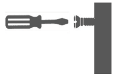
NOTE: You will need for the assembly a Phillips screwdriver and mallet/hammer (not included).
MAIN PARTS LAYOUT (FOR REFERENCE):

 This unit uses cam bolts and locks. The following explains how to use them.
This is not an assembly step; it is a guide for when you are actually doing the assembly using this kind of hardware.

- Screw the bolt into the corresponding hole on panel “A”.
- Join panel “B” to panel “A”. If panel “B” comes with the cam lock pre-installed, make sure it is aligned to receive the bolt’s head (refer to point 3). There might be a very small gap between the panels which is normal.

- Insert the cam lock on panel “B” making sure it goes aligned to receive the bolt’s head.
- Turn the cam lock clockwise. This will lock the parts together and will close any gaps.

BEFORE YOU START THE ASSEMBLY, PLEASE READ THE FOLLOWING TIPS AND WARNINGS.
Do a quick inventory to make sure the package contains all the parts and hardware listed in the assembly instructions.

Missing, damaged and defective parts can be replaced at no cost to you. Please refer to the last pages on this manual.
 The replacement parts service is limited to the 48 contiguous United States.
If you reside in Alaska, Hawaii, Puerto Rico, U.S. territories or other countries, please contact the supplier from where the unit was purchased.

If during assembly you find an issue or need clarification, please contact our Customer Service for assistance.
Please refer to the last pages on this manual.

On each step read the instructions and analyze the illustrations thoroughly before proceeding to do the assembly.

Make sure you understand which hardware will be used on each step. Using the wrong size of screw, bolt or pin might strip the threads or cause damage to the part in which it is being used.
To avoid misalignments, always leave the screws loose and tighten them until all pieces are positioned correctly.
Do not overtighten or force the screws as they might break, strip, damage the threads of the holes or get stuck inside the part.
Sometimes the laminate might cover partially or entirely the hole on a panel. If there is no visible hole for the screw, pass and press the tip of your finger over the area where the hole should be located to feel the indentation, and once found, carefully pierce the laminate to reveal the hole underneath.

# If the hole seems too small for the screw, first make sure you are using the correct size of screw and that it’s been installed in the correct hole. If the hole still appears to be too small, carefully pierce the laminate to reveal the hole’s actual size.

ASSEMBLY STEPS
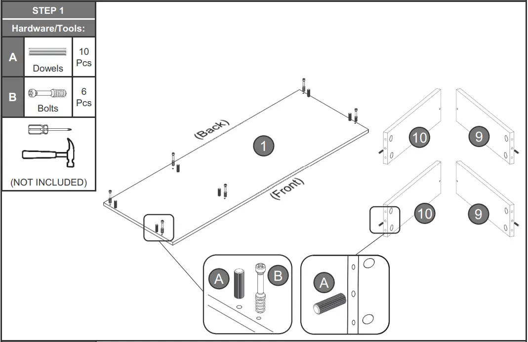
Place the main panel 1 upside-down over a blanket to protect its finish, and attach the dowels A into the innermost holes, and the bolts B into the outermost holes as shown. Then attach the dowels A into the center hole on the profile of panels 9 and 10.
With the help of another person, insert and align the cam locks C into panel 2 and assemble it to the main panel 1 as shown and as explained in page 4. Then cover the cam locks with the stickers I. Finally, assemble the back panel 3 to panel 2 with screws D from the exterior.

Separate all the sliders pieces O according to their shape (no assembly is done here):
-The “Flat” ones will be used in the next step.
-The “L” shaped go on the drawer and will be used until step 15.

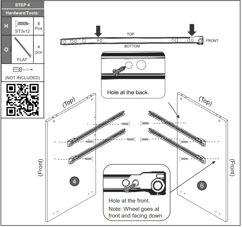
With panels 4 and 6 oriented as shown, attach to them the flat sliders O with screws H. The wheels go towards the front and facing down. For best results, attach at the front of the panels first.
Insert and align the cam locks C into panel 4 and assemble it to the main panel 1 as shown and as explained in page 4. Then cover the cam locks with the stickers I. Finally, secure the panel 4 to panel 3 with screws D as shown.

Assemble the lower panel 5 to panel 4 with screws D from the inside.

Insert and align the cam locks C into panel 6 and assemble it to the main panel 1 as shown and as explained in page 4. Then cover the cam locks with the stickers I. Finally, secure the panel 6 to panel 5 with screws D as shown.

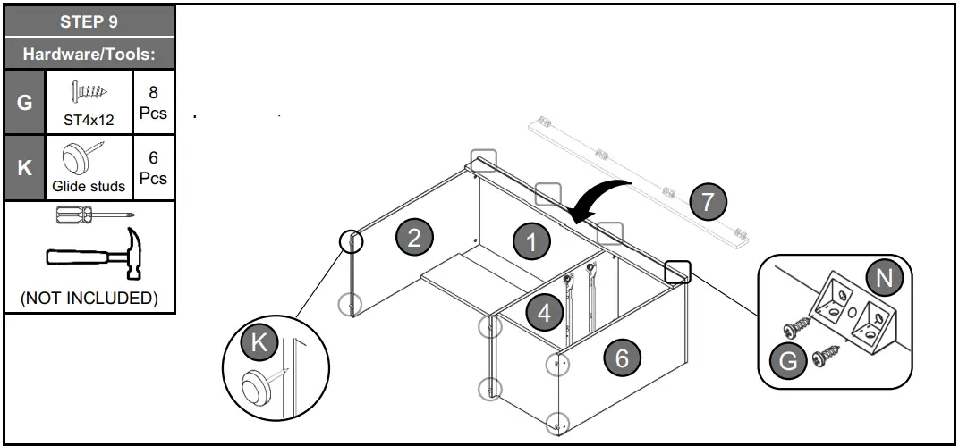
Align the corner of the brackets N along the edge of the top front panel 7 and secure them with screws G as shown.

Place panel 7 over the unit making sure it is flushed with the main panel 1 and that it aligns on both ends, and secure it to panel 1 with screws G through the brackets N. Then attach the glide studs K on the bottom of panels 2, 4 and 6 as shown.
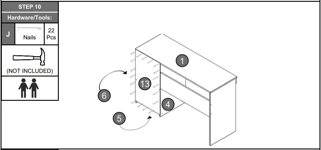
With the help of another person, bring the unit to the upright position, then assemble the back panel 13 with nails J making sure the panel aligns and fit over all the profiles of panels 1, 4, 5 and 6 as shown.
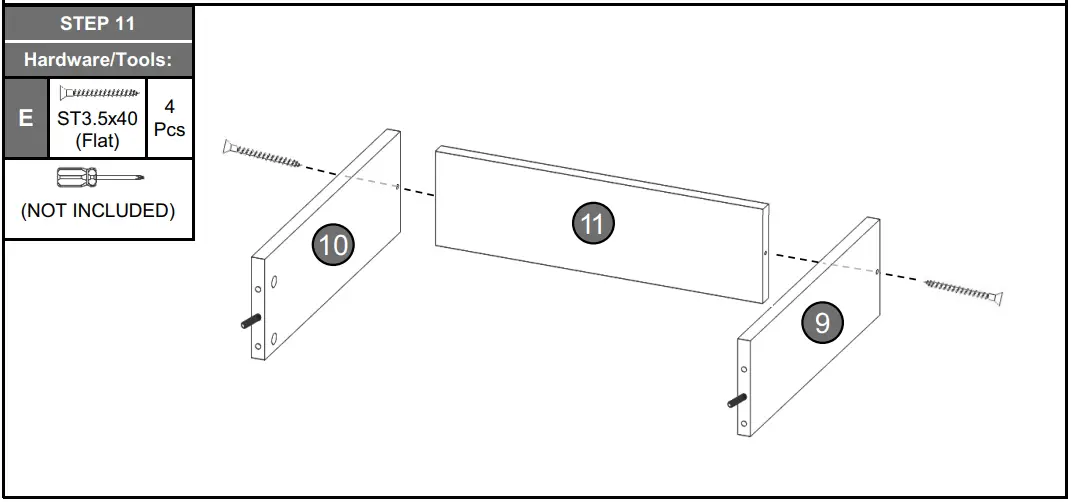
For each drawer, assemble panels 9 and 10 to panel 11 with screws E as shown.
 For each drawer, attach the bolts B to the indicated holes on panel 8. Then insert and align the cam locks C into panels 9 and 10 and assemble them to panel 8 as shown and as explained in page 4. Finally, cover the cam locks with the stickers I.
 For each drawer, assemble the handle L to the drawer front panel 8 with screws F from inside.
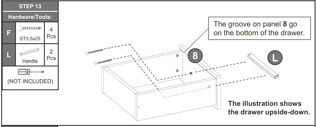 For each drawer, place the panel 12 on the bottom of the drawer making sure it enters into the groove of panel 8, then secure panel 12 to panels 9, 10and 11 with nails J as shown.
 For each drawer, assemble the L-Shaped sliders O to the bottom of the drawer with screws H.
IMPORTANT: Please pay attention to the orientation of the sliders as indicated.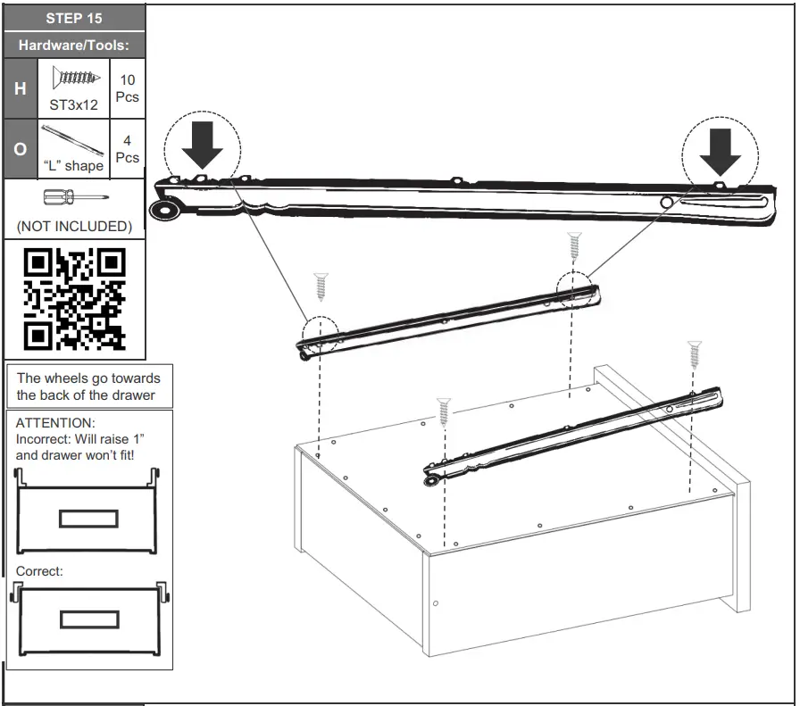
Insert the drawers into the unit starting with the bottom one. You might need to insert them an angle with the front facing down.
If the drawers don’t fit, please review the assembly of the steps 4 and 15.  AFTER THE ASSEMBLY IS DONE, PLEASE READ CAREFULLY THE FOLLOWING CARE AND MAINTENANCE WARNINGS:
- Do not exceed the indicated weight limits.
- Do not expose the surfaces to direct sunlight or to extreme environmental conditions.
- Clean the surfaces preferable with a clean cloth damped in a solution of mild soap and ater, then dry with a clean towel.
- Do not use solvents or abrasive materials to clean the unit.
- If you decide to use a cleaning agent, test first on an area hidden from view such as underneath the tabletop.
- Do not sit on the unit or lean against it.
- Do not allow small children to play under or over the unit.
- Do not allow small children to reach inside the drawers without your supervision.
- Do not pull, push or drag the unit to move it for more than 1 feet. The unit must be lifted by at least 2 persons when moving in the same or adjacent rooms.
- Before moving the unit, make sure to secure or remove any object that is heavy or might fall off.
- When lifting the unit, use both hands and bend your knees, not your backs.
- When transporting the unit to places far away, protect and secure the unit to avoid damage in transit.
- Shall any part of the unit become defective during the warranty period, replacement parts might be available to you at no charge. Please refer to the last pages on this manual.
- The warranty does not extend to regular wear and tear, nor the manufacturer assumes liability for damages or consequences due to accidents, incorrect assembly, negligence, improper use, modifications, or not heeding the above warnings.
Replacement parts can only be supplied if parts are available. Items out of production may be unavailable. This warranty will be effective for the applicable time period beginning the date of purchase on your original sales receipt. RTA product’s obligation under this warranty is limited to repairing or replacing products or parts as provided herein. This product has been designed for and is intended for office and home-office use only. This warranty is Original Purchaser’s sole remedy for product defects, and this warranty does not extend to any product, or damage to any product, caused by or attributed to abuse or misuse, products used for commercial or rental purposes, use modifications of, or attachments to the product, and products or parts not used, maintained, or extended hereunder is in lieu of any and all other warranties, express or implied, including without limitations any implied warranty or merchantability or of fitness for a particular purpose. Please note, all desks made with PVC Laminate surface should not be exposed to direct sunlight, as it may damage the material. Damage of this nature is not covered under this warranty.
RTA Products will not be responsible for indi rect, special, incidental or consequential damages. This warranty is limited to merchandise purchased in the Continental United States, excludes AK, HI and PR. Some States do not allow the exclusion or limitation of
incidental or consequential damages, so the above limitations or exclusions may not apply to you. This warranty gives you specific legal rights. You may also have other rights that may vary from state to state.
RTA Products will advise you of the procedure to follow in making warranty claims. The following are the procedures for warranty claims:
a. Call us Monday – Friday, from 9am-5pm (Eastern Time) at 866-782-5520 to explain the defect and give your name, address and phone number. Please have ready the model number of our product, date and place of purchase. You can also write to us by e-mail to [email protected] and include the same information.
b. If we determine that replacement will remed tyhe situation, and in order to determine the extent or the cause of the defect, purchaser will need to send the part in question at purchaser’s expense. Once we receive the part, we will examine it and determine whether the claim is valid (or not), and then proceed to send the replacement. We will ship the replacement at our expense.
INCLUDING REPLACEMENT PARTS ORDERS
VISIT: WWW.TECHNIMOBILI.COM
 https://technimobili.com/pages/order-parts
Scan QR Code to order replacement parts
OR EMAIL US: [email protected]