SBP 1000-1500 E Buffer Cylinder
Instruction Manual » SBP 1000 E » SBP 1010 E » SBP 1500 E » SBP 1000 E SOL
» SBP 1500 E SOL » SBP 1000 E cool » SBP 1010 E cool » SBP 1500 E cool
OPERATION AND INSTALLATION
Buffer cylinder
Contents
General information
The chapter “Operation” is intended for appliance users and heating contractors.
The chapter “Installation” is intended for heating contractors.
Note
Read these instructions carefully before using the appliance and retain them for future reference.
Pass on the instructions to a new user if required.
1.1 Safety instructions
1.1.1 Structure of safety instructions
KEYWORD Type of risk
Here, possible consequences are listed that may result from failure to observe the safety instructions.
- Steps to prevent the risk are listed.
1.1.2 Symbols, type of risk
| Symbol | Type of risk |
| Injury | |
| Burns (burns, scalding) |
1.1.3 Keywords
| KEYWORD | Meaning |
| DANGER | Failure to observe this information will result in serious injury or death. |
| WARNING | Failure to observe this information may result in serious injury or death. |
| CAUTION | Failure to observe this information may result in nonserious or minor injury. |
1.2 Other symbols in this documentation
Note
General information is identified by the symbol shownon the left.
- Read these texts carefully.
| Symbol | Meaning |
| Material losses (appliance, consequential, environment) | |
| Appliance disposal |
This symbol indicates that you have to do something. The action you need to take is described step by step.
1.3 Units of measurement
Note
All measurements are given in mm unless stated otherwise.
Safety
2.1 Intended use
This appliance is generally intended to be used for the storage, heating and cooling of process water.
SBP E cool appliances are also permitted to store cooled process water down to + 7 °C.
Any other or additional use is inappropriate, in particular usage with alternative storage media. Observation of these instructions and of instructions for any accessories used is also part of the correct use of this appliance.
2.2 General safety instructions
WARNING Burns
There is a risk of scalding at outlet temperatures in excess of 43 °C.
WARNING Injury
The appliance may be used by children aged 8 and up and persons with reduced physical, sensory or mental capabilities or a lack of experience provided that they are supervised or they have been instructed on how to use the appliance safely and have nderstood the resulting risks.
Children must never play with the appliance.
Children must never clean the appliance or perform user maintenance unless they are supervised.
Appliance description
Suitable heat exchangers, flanged and threaded immersion heaters can be fitted by contractors.
This must be combined with thermal insulation WD cool.
Cleaning, care and maintenance
- Have a contractor regularly check the appliance, the safety assembly and all fitted accessories.
- Never use abrasive or corrosive cleaning agents. A damp cloth is sufficient for cleaning all plastic parts.
Troubleshooting
6.1 General safety instructions
We can only guarantee trouble-free function and operational reliability if riginal spare parts intended for the appliance are used.
6.2 Regulations, standards and instructions
Observe all applicable national and regional regulations and instructions.
Appliance description
Delivered with the appliance:
– additional type plate only SBP 1010 E:
– Insulation set for blank flange (nominal diameter DN 80)
7.2 Accessories
7.2.1 Required accessories
Depending on the static pressure, safety assemblies and pressure reducing valves are available. These type-tested safety assemblies protect the appliance against unacceptable excess pressure.
7.2.2 Further accessories
In addition, heat exchangers, flanged and threaded immersion heaters and thermal insulation are available as accessories.
Preparations
8.1 Installation site
- Always install the appliance in a room free from the risk of frost.
- Ensure the floor has sufficient load bearing capacity and evenness (see chapter “Specification / Data table”).
- Observe the room height and height when tilted (see chapter “Specification / Data table”).
Minimum clearances Maintain the minimum clearances.
8.2 Transport
Use the lifting eyes at the top of the appliance to assist handling.
Preparing for installation
- Position the appliance in its intended site.
- Fit the thermal insulation according to the instructions supplied.
For this, ensure that there is enough space for the installation task. You can then link the appliance into the heating system.
- Cover
- Top thermal insulation section (only WDH cool)
- Top thermal insulation section
- Top thermal insulation ring
- Convection brake (only WDH cool)
- R.h. thermal insulation section
- Cover strip
- Flange thermal insulation ring
- Connection cover (including insulation)
- Flange cover
- Thermal insulation, flange
- Plastic cover with insulation sections
- Fleece strip
- Thermal insulation section, bottom
- Thermal insulation ring, bottom
- Rose
- Left thermal insulation section
- On cylinders supplied horizontally, insert the bottom thermal insulation section inside the support ring, prior to positioning the cylinder. Slightly tip the vertically delivered cylinder in order to position the bottom thermal insulation section.
- Surround the support ring with the bottom thermal insulation ring and secure it with adhesive tape.
- Remove the foil from the 5 foam strips (convection brakes) and stick them around the cylinder in the positions shown (only WDH cool).
- Prior to fitting them, shape the right hand and left hand thermal insulation sections into a semi-circular form for approx. 10 seconds. A pressure-activated adhesive then holds the thermal insulation sections in the required shape and makes fitting them easier. Please note that the use of tensioning straps may damage the thermal insulation.
- Push the thermal insulation sections over the connections on the appliance.
- Connect the thermal insulation sections at the front by clipping the hook closure strip into the last hook strip. If necessary, the short black cover strips can be used to temporarily hold the hook closure strips together.
- Position the thermal insulation sections around the cylinder and connect the thermal insulation sections at the back by clipping the hook closure strip into the first or second hook strip.
- Adjust the thermal insulation sections on the appliance by patting and pressing them down with the palm of the hand.
- Starting from the top, retighten the hook closure strip from the top until it hooks into the final hook strip.
- Place the thermal insulation ring around the flange to completely fill the gap to the side insulation segments.
- Place the thermal insulation ring and the two thermal insulation sections on the top.
- Place the cover over the thermal insulation sections.
- Fit the cover strips onto the hook closure strips. If required, the cover strips can be trimmed to size.
- Fill the hollow spaces near the connections with the soft foam inserts.
- Push the roses and caps into the apertures. SBP 1010 E:
- Wrap the fleece strip around the neck of the blank flange (DN 80).
- Place the plastic cover together with the thermal insulation onto the blank flange (DN 80).
Affix the additional type plate in a clearly visible position on the thermal insulation.
9.2 Installing the manual air vent valve
- Install a manual air vent valve at the air vent valve connection.
9.3 Fitting the temperature sensor
- Fill the protective pipe with heat conducting paste.
- Insert the sensor into the protective pipe until it bottoms.
- Prior to inserting contact sensor AVF 6 into the protective pipe, bend the bias spring forward.
9.4 Where appropriate, fit the flanged or threaded immersion heater.
- Remove the dummy flanges and plugs in order to mount the heat exchanger, flanged or threaded immersion heater. Maintain the DC separation towards the cylinder.
Commissioning
A glycol/water mixture of up to 60 % is permitted for the indirect coil in the solar circuit if only dezincification-resistant metals, glycol-resistant gaskets and diaphragm expansion vessels suitable for glycol are used throughout the installation.
Oxygen diffusion
Material losses
Avoid open heating systems and plastic pipes in underfloor heating systems which are permeable to oxygen.
In underfloor heating systems with plastic pipes that are permeable to oxygen and in open vented heating systems, oxygen diffusion may lead to corrosion on the steel components of the heating system (e.g. on the indirect coil of the DHW cylinder, on buffer cylinders, steel heating elements or steel pipes).
Material losses
The products of corrosion (e.g. rusty sludge) can settle in the heating system components and can result in a lower output or fault shutdowns due to reduced cross-sections.
Material losses
Avoid open vented solar thermal systems and plastic pipes which are permeable to oxygen.
Material losses
A safety valve is required.
- Fill and vent the appliance.
- Carry out a tightness check.
- Vent the internal indirect coil.
- Switch the mains power ON if required.
- Check the function of the safety assembly.
- Check the function of fitted accessories.
- Then check the function of the solar thermal system, if appropriate.
- If relevant, check that the DHW temperature displayed on the heat source control unit is correct.
- Explain the appliance function to users and familiarise them with its operation.
- Make users aware of potential dangers, especially the risk of scalding.
- Hand over these instructions.
See chapter “Commissioning”.
Shutting down
- If necessary, disconnect any accessories installed from the mains at the MCB/fuse in the fuse box.
- Drain the appliance. See chapter “Maintenance / Draining the appliance”.
Maintenance
No special maintenance is required for the appliance. A regular visual check is sufficient.
12.1 Draining the appliance
WARNING Burns
Hot water may escape during the draining process.
If the appliance needs to be drained for maintenance or to protect the whole installation when there is a risk of frost, proceed as follows:
- For draining the appliance, remove the thermal insulation around the drain connector.
Specification
SBP 1000 E | SBP 1000 E SOL
| SBP 1000 E | SBP 1000 E SOL | ||||
| d01 | Heat pump flow | Nominal diameter | DN 80 | DN 80 | |
| d02 | Heat pump return | Nominal diameter | DN 80 | DN 80 | |
| d25 | Solar flow | Female thread | G 1 | ||
| d26 | Solar return | Female thread | G 1 | ||
| d35 | Heat source flow optional | Female thread | G 1 1/2 | G 1 1/2 | |
| d36 | Heat source return optional | Female thread | G 1 1/2 | G 1 1/2 | |
| d46 | Ventilation | Female thread | G 1/2 | G 1/2 | |
| d47 | Drain | Male thread | G 3/4 A | G 3/4 A | |
| e01 | Heating flow | Nominal diameter | DN 80 | DN 80 | |
| e02 | Heating return | Nominal diameter | DN 80 | DN 80 | |
| h02 | Sensor heat pump return | Diameter | mm | 9.5 | 9.5 |
| h22 | Sensor heat source | Diameter | mm | 9.5 | 9.5 |
| h28 | Sensor solar cylinder | Diameter | mm | 9.5 | 9.5 |
| h43 | Thermometer | Diameter | mm | 14.5 | 14.5 |
| i01 | Flange | Diameter | mm | 280 | 280 |
| Pitch circle diameter | mm | 245 | 245 | ||
| Screws | M 14 | M 14 | |||
| i07 | Electric emergency/booster heater | Female thread | G 1 1/2 | G 1 1/2 |
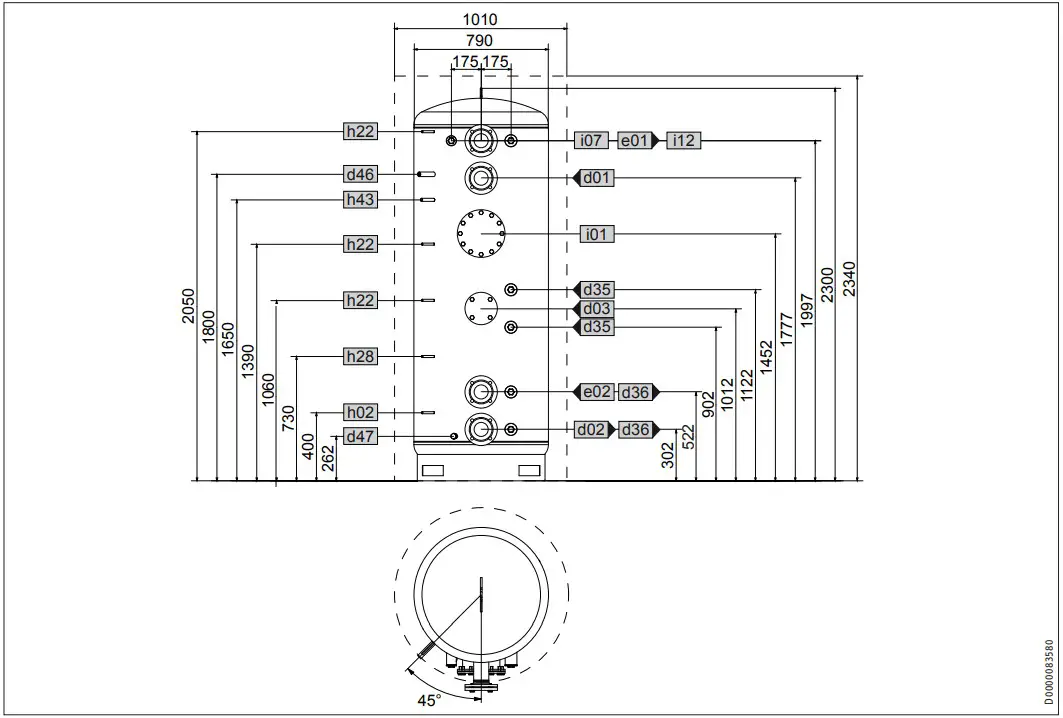
| SBP 1010 E | ||||
| d01 | Heat pump flow | Internal diameter | DN 80 | |
| d02 | Heat pump return | Internal diameter | DN 80 | |
| d03 | Heat pump flow optional | Internal diameter | DN 80 | |
| Pitch circle diameter | mm | 150 | ||
| Screws | M 16 | |||
| Female thread | G 2 | |||
| d35 | Heat source flow optional | Female thread | G 2 | |
| d36 | Heat source return optional | Female thread | G 1/2 | |
| d46 | Ventilation | Male thread | G 3/4 A | |
| d47 | Drain | Internal diameter | DN 80 | |
| e01 | Heating flow | Internal diameter | DN 80 | |
| e02 | Heating return | Diameter | mm | 9,5 |
| h02 | Sensor heat pump return | Diameter | mm | 9,5 |
| h22 | Sensor heat source | Diameter | mm | 9,5 |
| h28 | Sensor solar cylinder | Diameter | mm | 14,5 |
| h43 | Thermometer | Diameter | mm | 280 |
| i01 | Flange | Pitch circle diameter | mm | 245 |
| Screws | M 14 | |||
| i07 | elec. emergency/booster heater | Female thread | G 1 1/2 | |
| i12 | Heat generator, opt. | Female thread | G 2 |
SBP 1500 E | SBP 1500 E SOL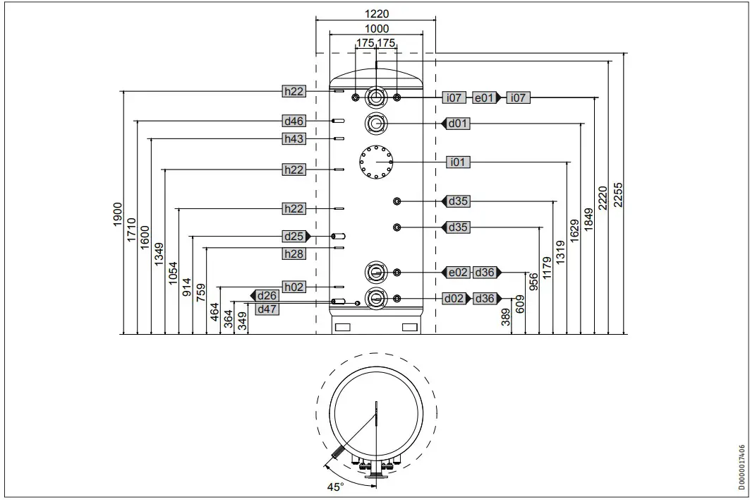
| SBP 1500 E | SBP 1500 E SOL | ||||
| d01 | Heat pump flow | Nominal diameter | DN 80 | DN 80 | |
| d02 | Heat pump return | Nominal diameter | DN 80 | DN 80 | |
| d25 | Solar flow | Female thread | G 1 | ||
| d26 | Solar return | Female thread | G 1 | ||
| d35 | Heat source flow optional | Female thread | G 1 1/2 | G 1 1/2 | |
| d36 | Heat source return optional | Female thread | G 1 1/2 | G 1 1/2 | |
| d46 | Ventilation | Female thread | G 1/2 | G 1/2 | |
| d47 | Drain | Male thread | G 3/4 A | G 3/4 A | |
| e01 | Heating flow | Nominal diameter | DN 80 | DN 80 | |
| e02 | Heating return | Nominal diameter | DN 80 | DN 80 | |
| h02 | Sensor heat pump return | Diameter | mm | 9.5 | 9.5 |
| h22 | Sensor heat source | Diameter | mm | 9.5 | 9.5 |
| h28 | Sensor solar cylinder | Diameter | mm | 9.5 | 9.5 |
| h43 | Thermometer | Diameter | mm | 14.5 | 14.5 |
| i01 | Flange | Diameter | mm | 280 | 280 |
| Pitch circle diameter | mm | 245 | 245 | ||
| Screws | M 14 | M 14 | |||
| i07 | Electric emergency/booster heater | Female thread | G 1 1/2 | G 1 1/2 |
SBP 1000 E cool | SBP 1010 E cool
| SBP 1000 E cool | SBP 1010 E cool | ||||
| d01 | Heat pump flow | Internal diameter | DN 80 | DN 80 | |
| d02 | Heat pump return | Internal diameter | DN 80 | DN 80 | |
| d03 | Heat pump flow optional | Internal diameter | DN 80 | ||
| d35 | Heat source flow optional | Female thread | G 1 1/2 | G 1 1/2 | |
| d36 | Heat source return optional | Female thread | G 1 1/2 | G 1 1/2 | |
| d46 | Ventilation | Female thread | G 1/2 | G 1/2 | |
| d47 | Drain | Male thread | G 3/4 A | G 3/4 A | |
| e01 | Heating flow | Internal diameter | DN 80 | DN 80 | |
| e02 | Heating return | Internal diameter | DN 80 | DN 80 | |
| h02 | Sensor heat pump return | Diameter | mm | 9.5 | 9.5 |
| h22 | Sensor heat source | Diameter | mm | 9.5 | 9.5 |
| h28 | Sensor solar cylinder | Diameter | mm | 9.5 | 9.5 |
| h43 | Thermometer | Diameter | mm | 14.5 | 14.5 |
| i01 | Flange | Diameter | mm | 280 | 280 |
| Pitch circle diameter | mm | 245 | 245 | ||
| Screws | M 14 | M 14 | |||
| i07 | elec. emergency/booster heater | Female thread | G 1 1/2 | G 1 1/2 |
SBP 1500 E cool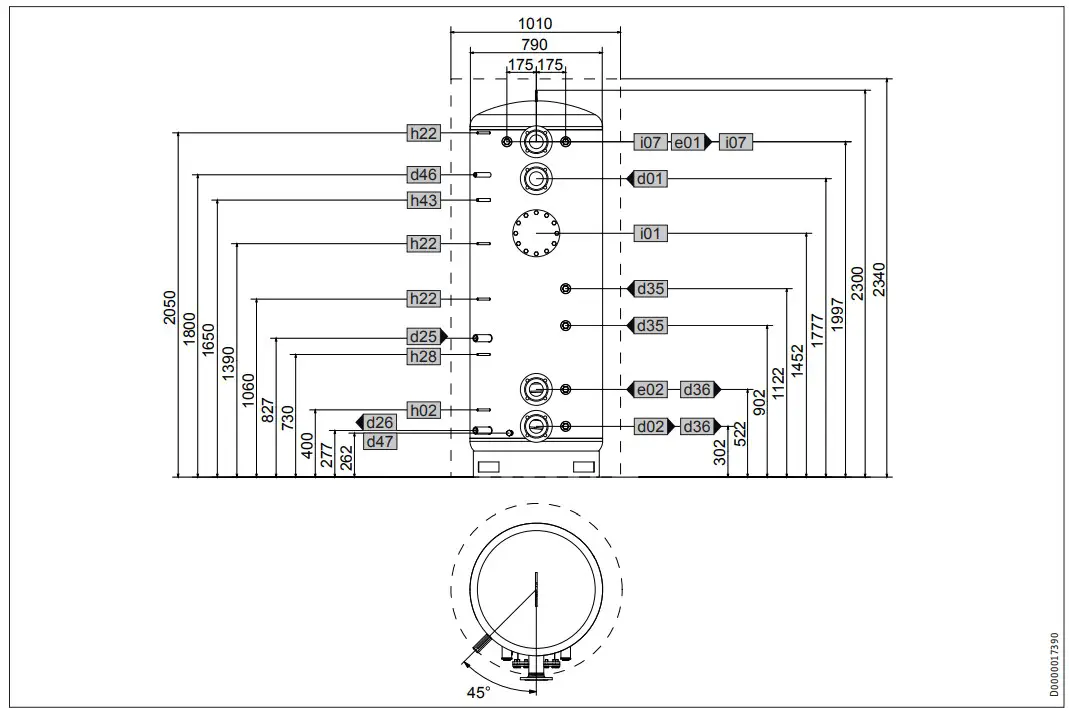
| SBP 1500 E cool | ||||
| d01 | Heat pump flow | Nominal diameter | DN 80 | |
| d02 | Heat pump return | Nominal diameter | DN 80 | |
| d35 | Heat source flow optional | Female thread | G 1 1/2 | |
| d36 | Heat source return optional | Female thread | G 1 1/2 | |
| d46 | Ventilation | Female thread | G 1/2 | |
| d47 | Drain | Male thread | G 3/4 A | |
| e01 | Heating flow | Nominal diameter | DN 80 | |
| e02 | Heating return | Nominal diameter | DN 80 | |
| h02 | Sensor heat pump return | Diameter | mm | 9.5 |
| h22 | Sensor heat source | Diameter | mm | 9.5 |
| h28 | Sensor solar cylinder | Diameter | mm | 9.5 |
| h43 | Thermometer | Diameter | mm | 14.5 |
| i01 | Flange | Diameter | mm | 280 |
| Pitch circle diameter | mm | 245 | ||
| Screws | M 14 | |||
| i07 | Electric emergency/booster heater | Female thread | G 1 1/2 |
13.2 Fault conditions
In the event of a fault, temperatures of up to 95 °C at 1.0 MPa can occur depending on the type of heart source used.
13.3 Data table
| SBP 1000 E | SBP 1010 E | SBP 1500 E | SBP 1000 E | SBP 1500 E | SBP 1000 E | SBP 1010 E | SBP 1500 E | ||
| SOL | SOL | cool | cool | cool | |||||
| 227564 | 236569 | 227565 | 227566 | 227567 | 227588 | 236570 | 227589 | ||
| Hydraulic data | |||||||||
| Rated capacity | l | 1006 | 1006 | 1503 | 979 | 1473 | 1006 | 1006 | 1503 |
| Capacity, lower indirect coil | l | 25.9 | 22.5 | ||||||
| Surface area, lower indirect coil | m² | 3 | 3.6 | ||||||
| Pressure drop at 1.0 m³/h, indirect coil, bottom | hPa | 8 | 9 | ||||||
| Application limits | |||||||||
| Max. permissible pressure | MPa | 0.3 | 1.0 | 0.3 | 0.3 | 0.3 | 0.3 | 1.0 | 0.3 |
| Test pressure | MPa | 0.45 | 1.5 | 0.45 | 0.45 | 0.45 | 0.45 | 1.5 | 0.45 |
| Maximum charge / discharge flow rate | m³/h | 12.5 | 12.5 | 15 | 12.5 | 15 | 12.5 | 12.5 | 15 |
| Max. permissible temperature | °C | 95 | 95 | 95 | 95 | 95 | 95 | 95 | 95 |
| Max. recommended collector aper- ture area | m² | 20 | 30 | ||||||
| Dimensions | |||||||||
| Height | mm | 2300 | 2300 | 2220 | 2300 | 2220 | 2300 | 2300 | 2220 |
| Height incl. thermal insulation | mm | 2340 | 2340 | 2255 | 2340 | 2255 | 2340 | 2340 | 2255 |
| Diameter | mm | 790 | 790 | 1000 | 790 | 1000 | 822 | 822 | 1032 |
| Diameter incl. thermal insulation | mm | 1010 | 1010 | 1220 | 1010 | 1220 | 1010 | 1010 | 1220 |
| Height of unit when tilted | mm | 2335 | 2335 | 2250 | 2335 | 2250 | 2335 | 2335 | 2250 |
| Weights | |||||||||
| Weight (wet) | kg | 1178 | 1239 | 1703 | 1224 | 1780 | 1187 | 1248 | 1742 |
| Weight (dry) | kg | 172 | 233 | 229 | 219 | 285 | 181 | 242 | 239 |
Guarantee
The guarantee conditions of our German companies do not apply to appliances acquired outside of Germany. In countries where our subsidiaries sell our products a guarantee can only be issued by those subsidiaries. Such guarantee is only granted if the subsidiary has issued its own terms of guarantee. No other guarantee will be granted.
We shall not provide any guarantee for appliances acquired in countries where we have no subsidiary to sell our products.
This will not affect warranties issued by any importers.
Environment and recycling
We would ask you to help protect the environment. After use, dispose of the various materials in accordance with national regulations.
Deutschland
STIEBEL ELTRON GmbH & Co. KG
Dr.-Stiebel-Straße 33 | 37603 Holzminden
Tel. 05531 702-0 | Fax 05531 702-480
[email protected]
www.stiebel-eltron.de
Verkauf
Tel. 05531 702-110 | Fax 05531 702-95108
[email protected]
Kundendienst
Tel. 05531 702-111 | Fax 05531 702-95890
[email protected]
Ersatzteilverkauf
www.stiebel-eltron.de/ersatzteile
[email protected]
| Australia STIEBEL ELTRON Australia Pty. Ltd. 294 Salmon Street | Port Melbourne VIC 3207 Tel. 03 9645-1833 | Fax 03 9644-5091 [email protected] www.stiebel-eltron.com.au |
Netherlands STIEBEL ELTRON Nederland B.V. Daviottenweg 36 | 5222 BH ‘s-Hertogenbosch Tel. 073 623-0000 | Fax 073 623-1141 [email protected] www.stiebel-eltron.nl |
| Austria STIEBEL ELTRON Ges.m.b.H. Gewerbegebiet Neubau-Nord Margaritenstraße 4 A | 4063 Hörsching Tel. 07221 74600-0 | Fax 07221 74600-42 [email protected] www.stiebel-eltron.at |
New Zealand Stiebel Eltron NZ Limited 61 Barrys Point Road | Auckland 0622 Tel. +64 9486 2221 [email protected] www.stiebel-eltron.co.nz |
| Belgium STIEBEL ELTRON bvba/sprl ‘t Hofveld 6 – D1 | 1702 Groot-Bijgaarden Tel. 02 42322-22 | Fax 02 42322-12 [email protected] www.stiebel-eltron.be |
Poland STIEBEL ELTRON Polska Sp. z O.O. ul. Działkowa 2 | 02-234 Warszawa Tel. 022 60920-30 | Fax 022 60920-29 [email protected] www.stiebel-eltron.pl |
| China STIEBEL ELTRON (Tianjin) Electric Appliance Co., Ltd. Plant C3, XEDA International Industry City Xiqing Economic Development Area 300385 Tianjin Tel. 022 8396 2077 | Fax 022 8396 2075 [email protected] www.stiebeleltron.cn |
Russia STIEBEL ELTRON LLC RUSSIA Urzhumskaya street 4, building 2 | 129343 Moscow Tel. +7 495 125 0 125 [email protected] www.stiebel-eltron.ru |
| Czech Republic STIEBEL ELTRON spol. s r.o. Dopraváků 749/3 | 184 00 Praha 8 Tel. 251116-111 | Fax 235512-122 [email protected] www.stiebel-eltron.cz |
Slovakia STIEBEL ELTRON Slovakia, s.r.o. Hlavná 1 | 058 01 Poprad Tel. 052 7127-125 | Fax 052 7127-148 [email protected] www.stiebel-eltron.sk |
| Finland STIEBEL ELTRON OY Kapinakuja 1 | 04600 Mäntsälä Tel. 020 720-9988 [email protected] www.stiebel-eltron.fi |
South Africa STIEBEL ELTRON Southern Africa (PTY) Ltd 30 Archimedes Road Wendywood Johannesburg, 2090 Tel. +27 10 001 85 47 [email protected] www.stiebel-eltron.co.za |
| France STIEBEL ELTRON SAS 7-9, rue des Selliers B.P 85107 | 57073 Metz-Cédex 3 Tel. 0387 7438-88 | Fax 0387 7468-26 [email protected] www.stiebel-eltron.fr |
Switzerland STIEBEL ELTRON AG Industrie West Gass 8 | 5242 Lupfig Tel. 056 4640-500 | Fax 056 4640-501 [email protected] www.stiebel-eltron.ch |
| Hungary STIEBEL ELTRON Kft. Gyár u. 2 | 2040 Budaörs Tel. 01 250-6055 | Fax 01 368-8097 [email protected] www.stiebel-eltron.hu |
Thailand STIEBEL ELTRON Asia Ltd. 469 Moo 2 Tambol Klong-Jik Amphur Bangpa-In | 13160 Ayutthaya Tel. 035 220088 | Fax 035 221188 [email protected] www.stiebeleltronasia.com |
| Japan NIHON STIEBEL Co. Ltd. Kowa Kawasaki Nishiguchi Building 8F 66-2 Horikawa-Cho Saiwai-Ku | 212-0013 Kawasaki Tel. 044 540-3200 | Fax 044 540-3210 [email protected] www.nihonstiebel.co.jp |
United States of America STIEBEL ELTRON, Inc. 17 West Street | 01088 West Hatfield MA Tel. 0413 247-3380 | Fax 0413 247-3369 [email protected] www.stiebel-eltron-usa.com |
United Kingdom and Ireland
STIEBEL ELTRON UK Ltd.
Unit 12 Stadium Court
Stadium Road | CH62 3RP Bromborough
Tel. 0151 346-2300 | Fax 0151 334-2913
[email protected]
www.stiebel-eltron.co.uk
Subject to errors and technical changes!
Stand 9734