SPECIALIZED Mountain and Active Electric Bike

Contents
INTRODUCTION
THIS BRIEF ASSEMBLY GUIDE CONTAINS IMPORTANT INFORMATION. PLEASE READ CAREFULLY AND STORE IN A SAFE PLACE.
This Assembly Guide shows you how to build your bicycle from out of the box. The directions covered in this guide are general guidelines and apply to all Specialized flat bar (mountain/active) bicycles. If you’re unsure of the correct setup of your bicycle, contact Specialized Rider Care or visit an Authorized Specialized Retailer.
This document is not intended as a use, service, repair, or maintenance guide. Please visit an Authorized Specialized Retailer for all service, repairs, or maintenance.
Some bicycles come with a specific User Manual. This assembly guide is not a replacement for your bicycle’s User Manual. The user manual contains important safety, performance, and technical information specific to your bicycle, which you should read and keep for reference.
You should also read the entire Specialized Bicycle Owner’s Manual (“Owner’s Manual”) as it has additional important, general information and instructions you should follow. If you don’t have a copy of the Owner’s Manual, you can download it at www.specialized.com or obtain it from Specialized Rider Care or your nearest Authorized
Specialized Retailer.
Additional safety, performance, and service information for specific components such as suspension or pedals on your bicycle or accessories such as helmets or lights, may also be available. In case of a conflict between the information in this assembly guide and information provided by a component manufacturer’s manuals, please contact Specialized Rider Care or an Authorized Specialized Retailer.
Please note all instructions and notices are subject to changes and updates without notice. Please visit www.specialized.com for periodic tech updates.
SYMBOLS
When reading this assembly guide, you will note various important symbols and warnings, which are explained below:
 |
WARNING! The combination of this symbol and word indicates a potentially hazardous situation which, if not avoided, could result in serious injury or death. Many of the Warnings say “you may lose control and fall.” Because any fall can result in serious injury or even death, we do not always repeat the warning of possible injury or death. |
 |
CAUTION: The combination of the safety alert symbol and the word CAUTION indicates a potentially hazardous situation, which, if not avoided, may result in minor or moderate injury, or is an alert against unsafe practices. |
| The word CAUTION used without the safety alert symbol indicates a situation which, if not avoided, could result in serious damage to the bicycle or the voiding of your warranty. | |
 |
This symbol alerts the reader to information that is particularly important. |
 |
This symbol means that high-quality grease should be applied as illustrated |
 |
This symbol means that carbon friction paste should be applied as illustrated to increase friction. |
 |
Tech tips are helpful tips and tricks regarding installation and use. |
 |
Refer to the Owner’s Manual supplied with your bicycle for more specific information. |
| Where applicable, refer to the User Manual supplied with your bicycle for more specific information. |
This assembly guide was drafted in the English language and may have been translated into other languages as applicable.
ADDITIONAL LANGUAGES ARE AVAILABLE FOR DOWNLOAD AT www.specialized.com.
ASSEMBLY
WARNING! Proper assembly requires basic mechanical skills and a set of high-quality tools such as a torque wrench. If you are unsure about the proper setup of your bicycle, it should be assembled by an Authorized Specialized Retailer.
BIKE INSPECTION
- When removing all the parts from the packaging, ensure nothing was damaged during shipping. Call Specialized Rider Care if you notice any damage.
TORQUE SPECIFICATIONS
- The torque specifications for the bicycle build can be found in the user manual supplied with the bicycle (where applicable) or printed on the part near the bolt you are torquing.
- General torque specifications may also be found in the Owner’s Manual.
WARNING! Correct tightening force on fasteners (nuts, bolts, screws) on your bicycle is important for your safety. If too little force is applied, the fastener may not hold securely. If too much force is applied, the fastener can strip threads, stretch, deform or break.
An incorrect tightening force can result in component failure, which can cause you to lose control and fall. Where indicated, ensure each bolt is torqued to specification. After your first ride, and consistently thereafter, recheck the tightness of each bolt to ensure secure attachment of the components.
PACKAGING
- Please keep all your packaging as you can reuse it to transport your bicycle.
 RECYCLE: Please follow your local recycling guidelines to dispose of the packaging responsibly.
WIRELESS COMPONENTS
- Bicycles equipped with wireless components must be charged before use. Please see the component manufacturer’s user manual for more information.
- When shipping the bicycle, ensure the component batteries are below 30% charge level.
REQUIRED TOOLS
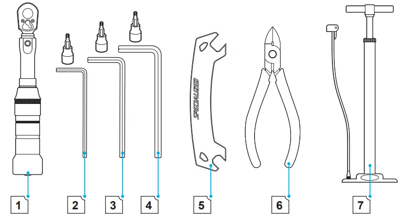
- Torque wrench (0 – 10 Nm)
- 4 mm hex key/bit
- 5 mm hex key/bit
- 6 mm hex key/bit
- 8 mm hex key/bit
- Flat wrench
- Side cutters
- Bicycle floor pump (with gauge)
WHAT’S IN THE SMALL PARTS BOX
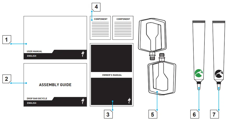
- User Manual (where applicable)
- Assembly Guide
- Component manuals
- Owner’s Manual
- Pedals (optional)
- High-quality grease
- High-quality carbon assembly paste (if your bicycle has a carbon frame).
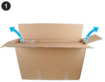
LET’S GET STARTED
The assembly of this bicycle is best completed with the help of another person.
- Remove any tape and open the top of the box.
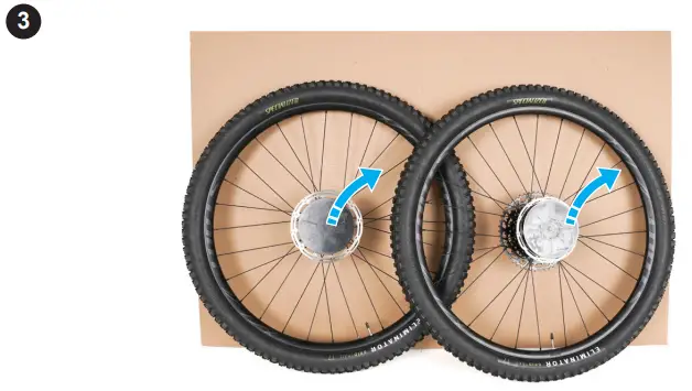
- Remove wheels with their packaging from the box and place them within easy reach.
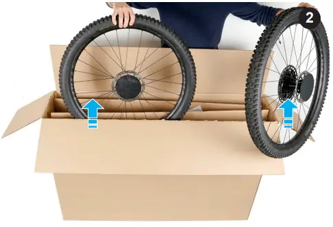
- Remove the hub protectors (A) from the axles.
When removing the hub protectors, ensure any hub end caps are not removed with the protector.
- Lift the bicycle and packaging out of the outer box.
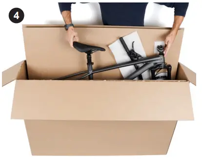
- Lay the bicycle and packaging on the ground in an open area with the frame facing up.
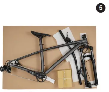
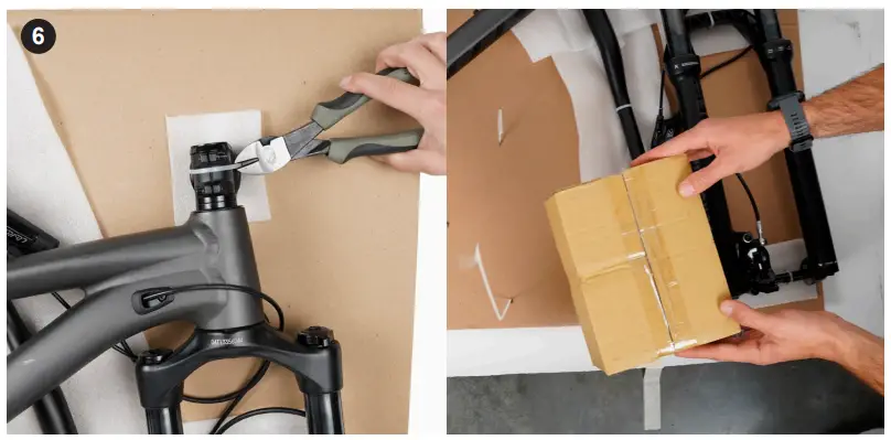
- Remove the zip ties from the frame and the packaging, then remove all the protective packaging. Locate and remove the small parts box, then remove all the parts supplied to assemble your bicycle.
CAUTION: Be careful not to damage the bicycle when removing zip ties.
CREATE THE BICYCLE ASSEMBLY STAND
- Lift the flap on the end of the outer box, push the inner cutout of the flap toward the inside of the box, then close the flap inward to create a cradle for the fork.
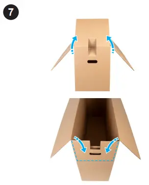
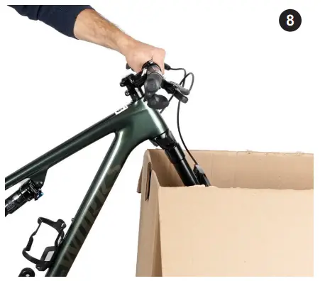
- Remove the bicycle from the packaging, then hang the fork and down tube in the cradle.
To hold the rear of the bicycle off the ground, place some extra packaging under the bottom bracket.
INSTALL THE REAR WHEEL
WARNING! A wheel attachment device that is not properly secured can allow the wheel to loosen or come off, suddenly stop the wheel, decrease your control, and cause you to fall, resulting in serious personal injury.
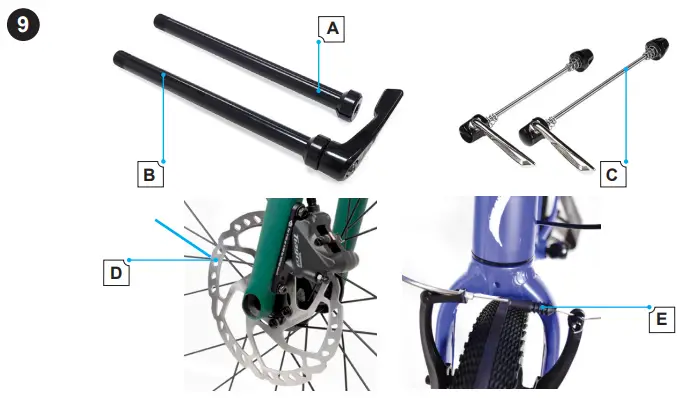
For more information on removing and installing wheels, please refer to the Owner’s Manual. - Determine which type of axle you have: (A) bolt-on thru-axle (BOTA), (B) fixed-lever thru-axle (FLTA) and adjustable-lever thru-axle (ALTA), or a (C) quick release skewer (QR-Skewer). Then determine what type of brakes you have: (D) DISC or (E) RIM. Follow the instructions for that type.
ALTA and FLTA have the same function; however, you are able to adjust the lever position of the ALTA after tightening - (DISC) Remove the rear brake pad spacer from the caliper.
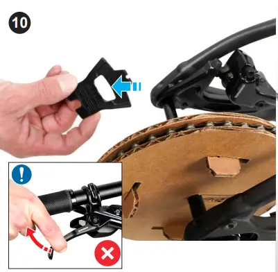
CAUTION: Do not pull the brake lever with the wheel removed and without a brake pad spacer installed.
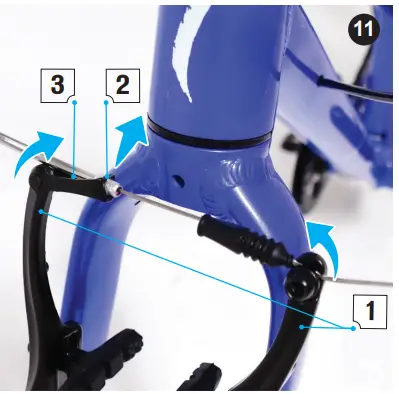
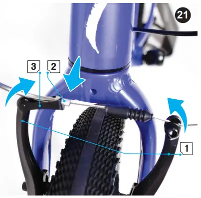
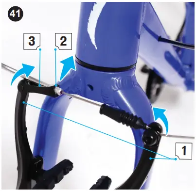
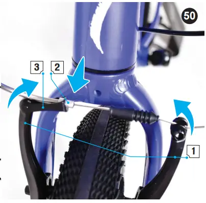
If the brake lever is accidentally pulled and the pads close, refer to the component manufacturer’s manual for more information. - (RIM) Disconnect the front brake cable by squeezing the brake arms together (1) and unhook the noodle end (2) from the quick release cradle (3).
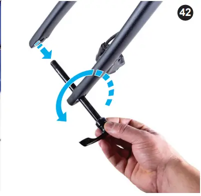
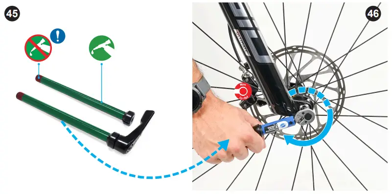
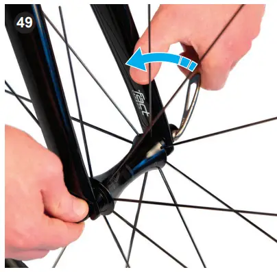
- (FLTA & ALTA) Rotate the lever (counter clockwise) on the thru-axle to loosen it and remove it from the frame.
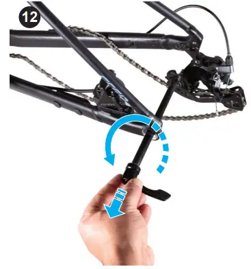
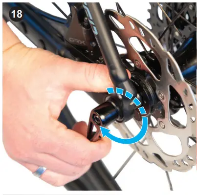
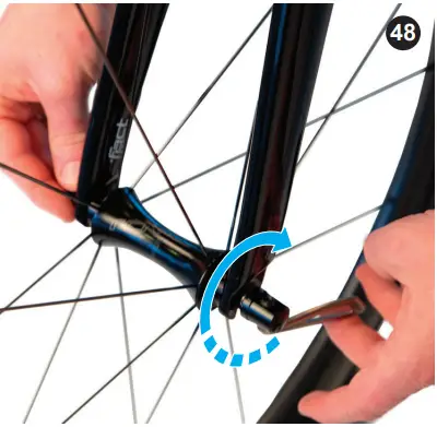
- (BOTA) Using the corresponding hex key, remove the thru-axle from the frame.
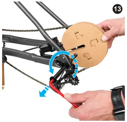
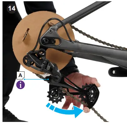
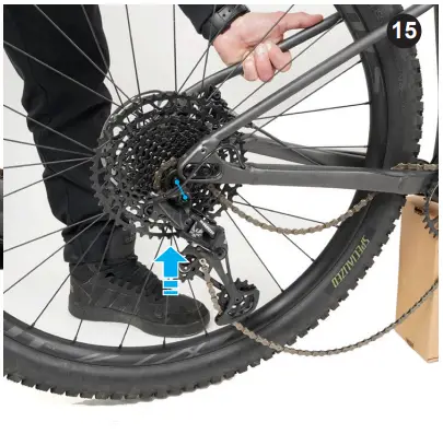
- Rotate the rear derailleur downward to release the tension on the chain. If there is a cage lock button (SRAM) (A) on the rear derailleur, press it to lock the derailleur open.
- Install the rear wheel into the rear frame, ensuring the disc brake is between the brake pads. Place the chain on the sprocket, then pull the wheel back until the chain is taut and the wheel is centered.
Ensure the derailleur is in the highest gear (smallest cog) before inserting the rear wheel.
- (BOTA, FLTA, and ALTA) Lightly grease the shaft of the thru-axle and slide it through the frame from the left (non-drive side) of the bicycle.
Do not grease the threads of the thru-axle. - (BOTA) Using a torque wrench and the corresponding hex bit, tighten the thru-axle (clockwise) to the specified torque setting found on the axle and/or in the user manual (where applicable).
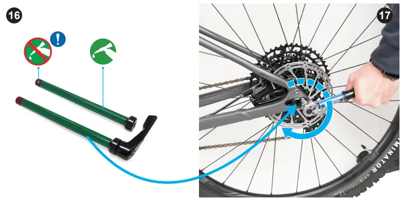
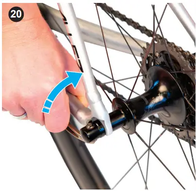
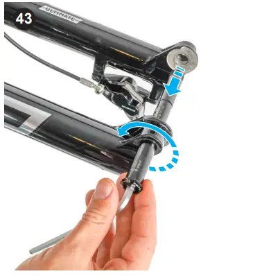
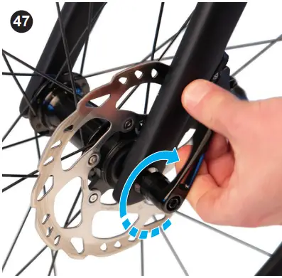
- (FLTA and ALTA) Rotate the lever (clockwise) into the frame. The lever leaves a clear imprint in the palm of your hand when sufficiently tightened.
- (QR-Skewer) Hold the skewer nut on the right side (drive-side) of the axle to stop it from rotating, then rotate the QR lever (clockwise) to lightly tighten the skewer until some resistance is felt.
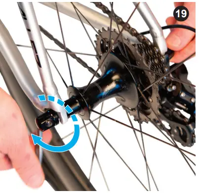
- (QR-Skewer) Close the lever. The lever leaves a clear imprint in the palm of your hand when sufficiently tightened.
WARNING: Securely clamping the wheel with a cam action retention device takes considerable force. If you can fully close the cam lever without wrapping your fingers around the seat stay or chainstay for leverage, the lever does not leave a clear imprint in the palm of your hand, and the serrations on the wheel fastener do not emboss the surfaces of the dropouts, the tension is insufficient. Open the lever, turn the tension adjusting nut clockwise a quarter turn, then try again.
- (RIM) Reconnect the front brake cable by squeezing the brake arms together (1) and inserting the cable noodle end (2) into the quick release cradle (3) .
ASSEMBLE THE HANDLEBAR
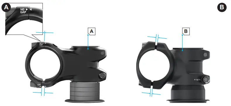
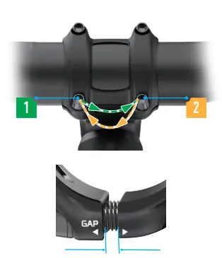
IDENTIFY THE STEMDetermine which type of stem you have: standard (A) or “No Gap”(B). Follow the instructions for that type.
STANDARD STEMS - Using the corresponding hex key, loosen (counterclockwise) and remove the four bolts on the stem faceplate, then remove the stem faceplate from the stem.
- Place the handlebar against the stem, then place the stem faceplate holes over the handlebar with the stem faceplate and stem holes aligned.
- Add a washer to each bolt and thread the bolts through each of the stem faceplate holes into the stem body making sure they are equally fingertightened.
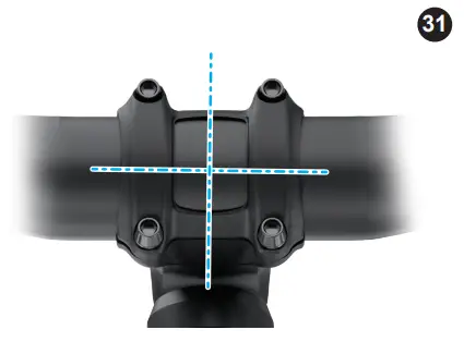
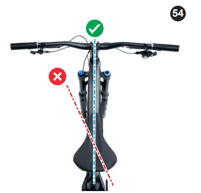
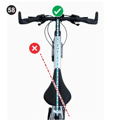
- Adjust the handlebar to the desired position making sure it is aligned with the center of the bicycle.
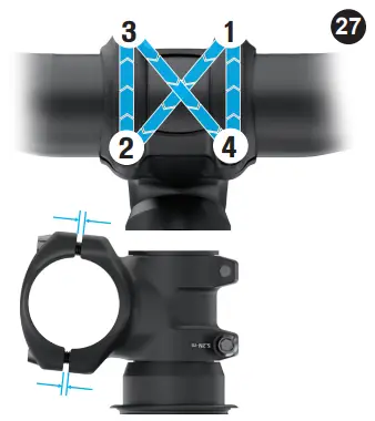
- Using a torque wrench and corresponding hex bit, torque each faceplate bolt approximately 1/2 turn at a time in an alternating (cross) pattern to the specified torque setting found on the stem and/or in the user manual (where applicable).
- The gap between the stem and faceplate should be even on the top and the bottom.
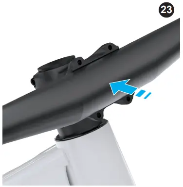
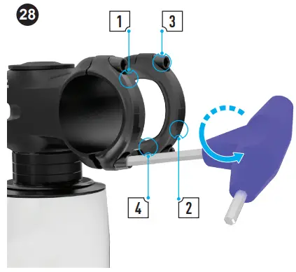
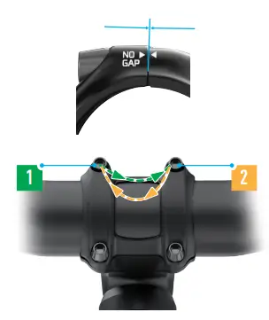
ALLOY TRAIL STEM (NO GAP STEM)
WARNING! The stem is designed without a gap between the stem body and the faceplate at the upper bolt area. The upper bolts must be tightened so the faceplate is flush against the stem body before being torqued. Failure to do this can result in structural damage to the handlebar.
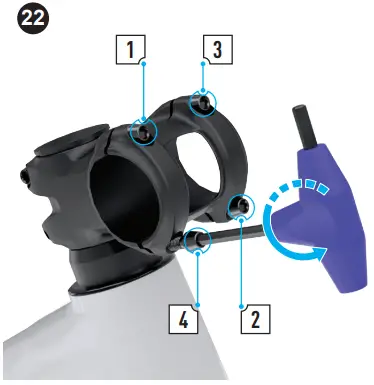
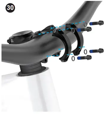
- Using the corresponding hex key, loosen (counterclockwise) and remove the four bolts on the stem faceplate, then remove the stem faceplate from the stem.
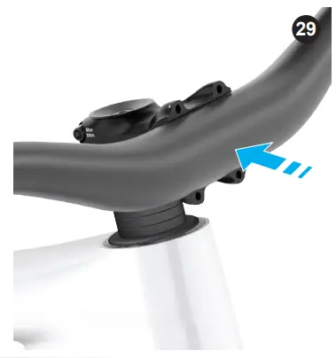
- Place the handlebar against the stem, then place the stem faceplate over the handlebar with the stem faceplate and stem holes aligned.
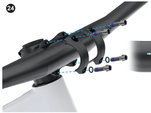
- Add the washer to each bolt and starting with the upper bolts, then thread the bolts through each of the stem faceplate holes into the stem body making sure they are equally finger-tightened.
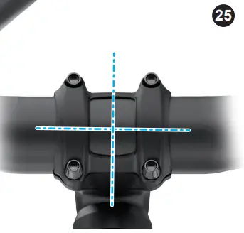
- Adjust the handlebar to the desired position making sure it is centered.
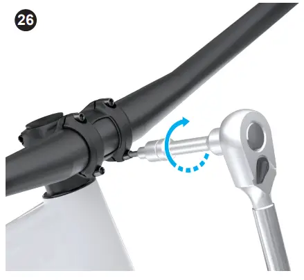
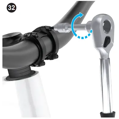
- Using a torque wrench and the corresponding hex bit, gradually torque the upper bolts, alternating from the left to the right, to the specified torque setting found on the stem and/or in the user manual (where applicable.
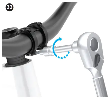
- Using a torque wrench and the corresponding hex bit, gradually torque the lower bolts, alternating from the left to the right, to the specified torque setting found on the stem and/or in the user manual (where applicable).
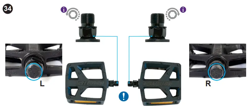
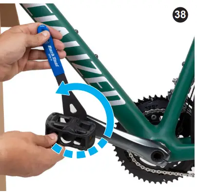
INSTALL THE PEDALS
Depending on the type, pedals are installed using either flat wrench or hex key.
CAUTION: Make sure to install the pedals correctly. The left and right pedals have opposite threads and can damage the cranks if installed on the wrong side.
When tightening, both pedal threads will rotate toward the front of the bicycle. - Remove the pedals from their packaging and locate the “L” and “R” markings.
- Lightly grease the threads on the “L” pedal and insert it into the left (non-drive side) crank arm.
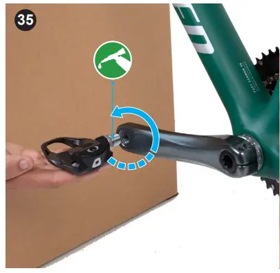
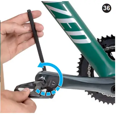
- HEX KEY PEDALS: Using the corresponding hex key inserted from the inside of the crank arm, tighten the pedal in place (counter-clockwise rotation). The tool leaves a clear imprint in the palm of your hand when sufficiently tightened.
- FLAT WRENCH PEDALS: Using the flat wrench, tighten the pedal in place (counter-clockwise rotation). The tool leaves a clear imprint in the palm of your hand when sufficiently tightened.
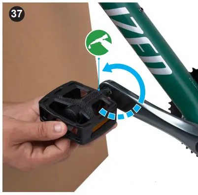
- Repeat these steps for the right “R” pedal on the right crank arm (drive side, clockwise rotation).
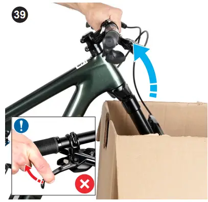
INSTALL THE FRONT WHEEL
WARNING! A wheel attachment device that is not properly secured can allow the wheel to loosen or come off, suddenly stop the wheel, decrease your control, and cause you to fall, resulting in serious personal injury.
For more information on removing and installing wheels, please refer to the Owner’s Manual.
Determine which type of axle you have: (A) bolt-on thru-axle (BOTA), (B) fixed-lever thru-axle (FLTA) and adjustable-lever thru-axle (ALTA), or a (C) quick release skewer (QR-Skewer). Then determine what type of brakes you have: (D) DISC or (E) RIM. Follow the instructions for that type. (Image 9) . - Lift the fork out of the packaging and remove the protective brace.
- (DISC) Remove the front brake pad spacer from the caliper.
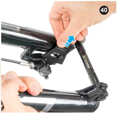
CAUTION: Do not pull the brake lever with the wheel removed and without a brake pad spacer installed.
- (RIM) Release the quick release lever on the side of the brake caliper to the upward position.
- (FLTA & ALTA) Rotate the lever on the thru-axle to loosen it and remove it from the fork.
- (BOTA) Using the corresponding hex key, remove the thru-axle from the fork.
- Install the front wheel into the fork ensuring the disc brake or tire is between the brake pads.
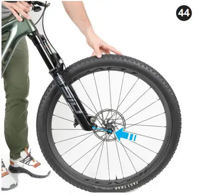
- Lightly grease the shaft of the thru-axle and slide it through the frame from the left (non-drive) side of the bicycle.
CAUTION: Do not grease the threads on the thru-axle.
- (BOTA) Using a torque wrench and corresponding hex bit, tighten the thru-axle (clockwise) to the specified torque setting found on the axle and/or in the user manual (where applicable).
- (FLTA & ALTA) Rotate the lever (clockwise) into the axle nut. The lever leaves a clear imprint in the palm of your hand when sufficiently tightened.
- (QR-Skewer) Hold the skewer nut on the drive side of the axle to stop it from rotating, then rotate the QR lever (clockwise) to lightly tighten the skewer until some resistance is felt.
- (QR-Skewer) Close the lever. The lever leaves a clear imprint in the palm of your hand when sufficiently tightened.
WARNING: Securely clamping the wheel with a cam action retention device takes considerable force. If you can fully close the cam lever without wrapping your fingers around the seatstay or chainstay for leverage, the lever does not leave a clear imprint in the palm of your hand, and the serrations on the wheel fastener do not emboss the surfaces of the dropouts, the tension is insufficient. Open the lever, turn the tension adjusting nut clockwise a quarter turn, then try again. - (RIM) Close the quick release lever on the side of the brake caliper to the downward position.
SEATPOST MINIMUM INSERTIONTo prevent damage to the frame and/or seatpost, it’s important to have a minimum amount of seatpost insertion in the seat tube. This minimum insertion must meet the following requirements:
- The seatpost must be inserted into the frame deep enough so the minimum insertion/maximum extension (min/max) mark, where applicable, on the seatpost is not visible (A) .
- The seatpost must also be inserted into the seat tube deep enough to meet or exceed (B) the minimum measured insertion depth required by the frame (C) .
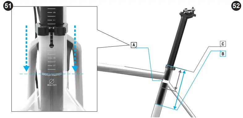
 Refer to the User Manual supplied with your bicycle (where applicable) for more specific information on the seatpost maximum and minimum insertion depths
WARNING! Failure to follow the outlined seatpost insertion requirements may result in damage to the frame and/or seatpost, which could cause you to lose control and fall.
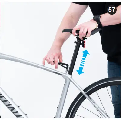
ADJUST THE SEATPOST HEIGHT
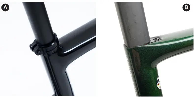
Determine which type of seat post you have; seatpost collar (A), or seatpost wedge (B). Follow the instructions for that type.
Shimano Di2. If the battery is located in the seatpost, follow the connection instructions shown in the bicycle’s user manual (where applicable).
Refer to the Owner’s Manual for more information on setting up your saddle height.
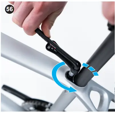
SEATPOST COLLAR - Using the corresponding hex key, loosen the seatpost collar bolt and set the saddle height to your desired position, then lightly tighten the seatpost collar bolt.
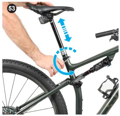
DROPPER SEATPOST: While raising or lowering the seatpost, push or pull the excess dropper cable from the front of the bicycle. - Align the saddle with the centerline of the bicycle.
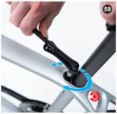
- Using the torque wrench and corresponding hex bit, torque the seatpost collar bolt to the specified torque setting found on the seatpost collar and/or in the user manual (where applicable).
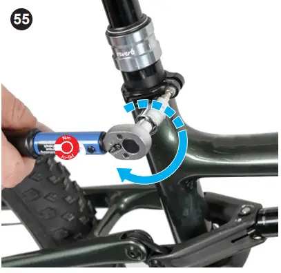
SEATPOST WEDGE
Front and rear seatpost wedges are adjusted the same way.
Shimano Di2. If the battery is located in the seatpost, follow the connection instructions shown in the bicycle’s user manual (where applicable). - Using the wrench and corresponding hex bit, loosen the seatpost wedge bolt.
- Adjust the seatpost to the desired height.
- Align the saddle with the centerline of the bicycle.
- Once the seatpost height is set, use a torque wrench and corresponding hex bit to torque the seatpost wedge bolt to the specified torque setting found on the wedge and/or in the user manual (where applicable).
PUMPING THE TIRES
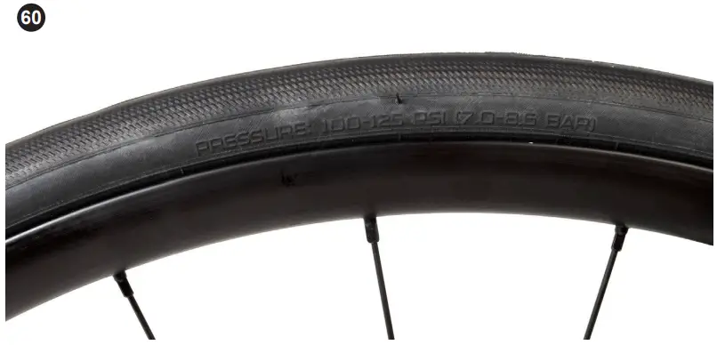
The tires must be inflated and periodically checked and reinflated using a pump with an accurate pressure gauge.
- . Pump the tires up to your desired pressure. Refer to the tires’ sidewall for pressure range. Check your wheel manual or decal on the rim itself to see if your wheels have a maximum pressure limit. Do not exceed it.
Please refer to the Tires and Tubes section of the Specialized Bicycle Owner’s Manual for additional information.
WARNING! Never inflate a tire beyond the maximum pressure marked on the tire’s sidewall or the maximum pressure limit specified by the wheel manufacturer, whichever is lower. Failure to follow this warning may cause the tire to blow off the rim and may result in serious personal injury.
SAFETY CHECK
WARNING! Before the first ride and routinely thereafter before each ride, perform the below safety check as well as any additional safety checks outlined in the Owner’s Manual to ensure the bicycle is safe to ride. Failure to follow this warning can result in serious personal injury.
- Nuts, bolts, screws, and other fasteners: Ensure the seatpost, stem, and handlebar are properly tightened. You can check the tightness of the handlebar, stem, and seatpost by securing the bicycle between your legs and trying to twist, push, and pull the handlebar and saddle. The handlebar and saddle should not move. If any components move, realign the part, increase the bolt tension, and try again. Repeat as necessary until there is no movement. Periodically check all the bolts on the bicycle to ensure they are torqued to specification using a torque wrench.
- Seatpost: Ensure the saddle height is appropriate. Adjust as necessary.
- Tires and wheels: Ensure the wheels spin freely and do not wobble. The wheels should be centered in the frame and fork. If the wheels wobble and are not centered, please contact Rider Care or visit an Authorized Specialized Retailer.
- Tire pressure: The tires must be inflated and periodically checked and re-inflated using a pump with an accurate gauge. Please refer to the Tires and Tubes section of the Specialized Bicycle Owner’s Manual supplied with your bicycle for additional information.
- Brakes: The brakes are pre-adjusted and aligned out of the box. If the brake pads or arms are misaligned, please contact Rider Care or visit an Authorized Specialized Retailer. Check the brake pads periodically for wear. Brake pads should be replaced once they wear down to the wear line. If the brake pads need to be replaced, but you do not have experience replacing brake pads, please contact Rider Care or visit an Authorized Specialized Retailer. Test the brakes by lifting one end of the bicycle at a time, spinning each wheel, and squeezing the brake lever. If the brakes are not working correctly, please contact Rider Care or visit an Authorized Specialized Retailer.
Regularly inspect the bicycle to ensure there is no damage to any of the components. Replace any worn or damaged components or have them replaced by an Authorized Specialized Retailer.