selec MV15 Voltmeter Instruction Manual
Contents
Voltmeter
(48 x 96)
(48 x 48)
(72 x 72)
(96 x 96)

| SPECIFICATIONS | |||||||
| AC MODEL | |||||||
| Product Name | MV15 | MV205 | MV305 | MV507 | MV207 | MV23073 Ø Digital voltmeter with Selector switch | |
| Description | 1 Ø Digital voltmeter | ||||||
| Display | 3 Digit 7 segment LED display 3 Digit, LCD with Analog style bar graph indication0 to 516V 0 to 300V (L-N)0 to 516V (L-L)50 to 480V AC50 / 60Hz516V“Or” for input > 516V 1M (±5%)1V | ||||||
| Display range | |||||||
| Input range | |||||||
| Input Frequency | |||||||
| Max continuous Input range | |||||||
| Over range indication | |||||||
| Input impedance | |||||||
| Resolution | |||||||
| Electrical connection | 1 Ø – 2 wire240V AC (± 20%), 50 / 60Hz ; 110V AC (± 20%), 60Hz | 3 Ø-4wire, 3 Ø-3wire 206gm |
|||||
| Supply Voltage(Vn) | |||||||
| Weight | 170gm | 180gm | 180gm | 165gm | 194gm | ||
| CE and UL Certification | YES | YES | CE ONLY | YES | YES | YES | |
| DC MODEL | AC MODEL ( AUTO RANGING TYPE ) | |||||
| Product Name | MV15-DC-20V | MV15-DC-200V | MV15-DC-200mV | MV15-DC-2V | MV15-AC-20/200V | MV15-AC-200/2000mV |
| Description | Digital voltmeter
3 ½ digit 7 Segment LED Display |
|||||
| Display | ||||||
| Display range | -19.99V to
+19.99V |
-199.9V to
+199.9V |
-199.9mV to
+199.9mV |
-1999mV to
+1999mV |
0 to 19.99/199.9V | 0 to 199.9/1999mV |
| Input range | 0 to ±20V | 0 to ±200V | 0 to ±200mV | 0 to ±2000mV | 0 to 20/200V | 0 to 200/2000mV |
| Input Frequency | 50 / 60Hz | |||||
| Max continuous Input range | ±19.99V | ±199.9V | ±199.9mV | ±1999mV | 19.99/199.9V | 199.9/1999mV |
| Over range Indication | “Or” for input> ±19.99V | “Or” for input> ±199.9V | “Or” for input> ±199.9mV | “Or” for input> ±1999mV | “Or” for input> 199.9V | “Or” for input> 1999mV |
| Resolution | 0.01 | 0.1 | 1 | 0.01/0.1 | 0.1/1 | |
| Electrical connection | 1 Ø – 2 wire240V AC (± 10%), 50 / 60Hz ; 110V AC (± 10%), 60Hz | |||||
| Supply Voltage(Vn) | ||||||
| Weight | 170gm | 170gm | 170gm | 170gm | 170gm | 170gm |
| CE and UL Certification | YES | YES | YES | YES | YES | YES |
Accuracy
Measurement Method: : ±0.5% of full scale over rated operating conditions
Sampling Rate: True RMS
Power consumption:3 samples / second
Measuring input overvoltage: 1.5 x Vn continuous, 2 x Vn (3s)
Environmental Conditions
Temperature: Operating: -10°C to 55°C Storage : -20°C to 75°C
Humidity: : Up to 95% RH(non condensing)
Altitude: Up to 2000 meters
Pollution degree: II
Installation Category: III (600V)
Protection Class: II
Mounting: Panel mounting
Ordering Information
Note : For CE and UL certified product, Add-CE ; -CU suffix to order code. For example MV15-DC-20V-CU ; MV305-CE For 110V Supply add -110V in order code For example MV15-DC-20V-110V-CU ; MV305-110V-CE
SAFETY PRECAUTIONS
All safety related codifications, symbols and instructions that appear in this operating manual or on the equipment must be strictly followed to ensure the safety of the operating personnel as well as the instrument. If the equipment is not used in a manner specified by the manufacturer it might impair the protection provided by the equipment.
- Do not use the equipment if there is any mechanical damage.
- Ensure that the equipment is supplied with correct voltage.
CAUTION
- Read complete instructions prior to installation and operation of the unit.
- Risk of electric shock.
- The equipment in its installed state must not come in close proximity to any heating sources, caustic vapors, oils, steam, or other unwanted process by products.
WIRING GUIDELINES
WARNING
- To prevent the risk of electric shock, power supply to the equipment must be kept OFF while doing the wiring arrangement.
- Wiring shall be done strictly according to the terminal layout. Confirm that all connections are correct.
- Use lugged terminals.
- To reduce electromagnetic interference use of wires with adequate ratings and twists of the same in equal size shall be made with shortest connections.
- Layout of connecting cables shall be away from any internal EMI source.
- Cable used for connection to power source, must have a 2 2 0 crosssectionof 0.5mm to 2.5mm (20 to 14AWG; 75 C(min)). The sewires shall have current carrying capacity of 6A.
- Copper cable should be used (Stranded or Single core cable)
- Before attempting work on device, ensure absence of voltages using appropriate voltage detection device.
NSTALLATION GUIDELINES
CAUTION :
- This equipment, being built-in-type, normally becomes a part of main control panel and in such case the terminals do not remain accessible to the end user after installation and internal wiring.
- Conductors must not come in contact with the internal circuitry of the equipment or else it may lead to a safety hazard that may in turn endanger life or cause electrical shock to the operator.
- Circuit breaker or mains switch must be installed between power source and supply terminals to facilitate power ‘ON’ or ‘OFF’ function. However this switch or breaker must be installed in a convenient position normally accessible to the operator. 4.
- Before disconnecting the secondary of the external current transformer from the equipment, make sure that the current transformer is short circuited to avoid risk of electrical shock and injury
- The equipment shall not be installed in environmental conditions other than those mentioned in this manual.
- The equipment does not have a built-in-type fuse. Installation of external fuse of rating 275V AC / Amp for electrical circuitry is highly recommended.
MECHANICAL INSTALLATION
For installing the meter
- Prepare the panel cutout with proper dimensions as shown below.
- Push the meter into the panel cutout. Secure the meter in its place by pushing the clamp on the rear side. The clamps must be secured in diagonally opposite slots.
- For proper sealing, tighten the screws evenly with required torque. Terminal screw tightening torque : 0.68 N-m to 0.79 N-m (6.018 In-Lb to 6.992 In-Lb) Screw clamp tightening torque : 0.1N-m (0.885 Lb-inch)
Outline Dimensions (in mm)
Panel cutout Dimensions (in mm)
MV507 MV15 MV305 MV2307
MAINTENANCE
- The equipment should be cleaned regularly to avoid blockage of ventilating parts.
- Clean the equipment with a clean dry or damp cloth.
Do not useany cleaning agent other than water.
TERMINAL CONNECTIONS
MV2307
MV15 / MV305 / MV15-AC
MV205
MV507

MV207
MV15-DC
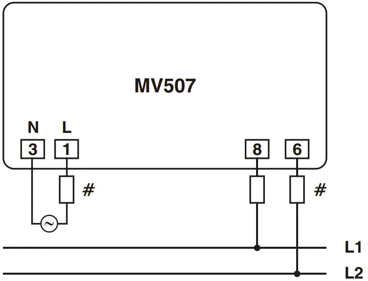
WIRING DIAGRAM
Case 1 for MV15 / MV305 / MV15-AC
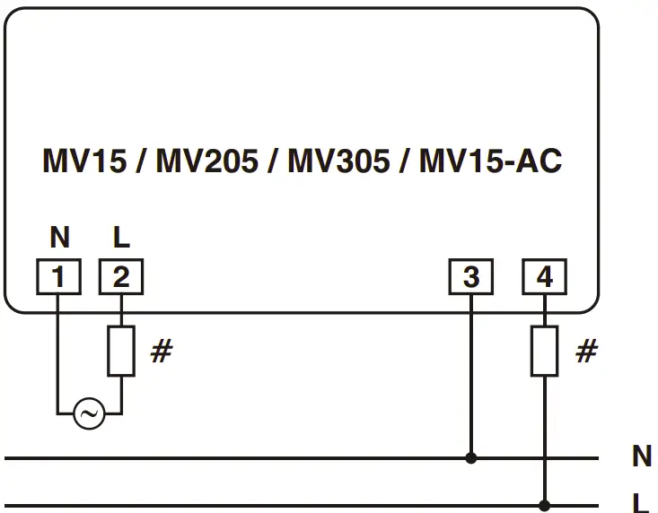
Case 2 for MV15 / MV205 / MV305

Case 1 for MV50

Case 2 for MV507
Case for MV205

Case 1 for MV207
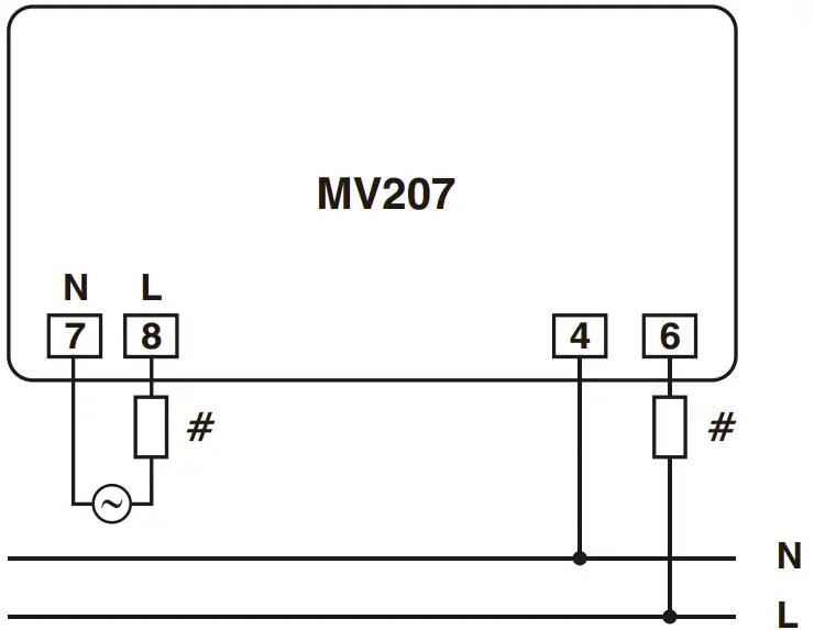
Case 2 for MV207
MV15 DC MODELS

MV2307

- All fuse types : 0.5A class CC UL type ; 0.5A fast acting 600V
MODE DESCRIPTION FOR MV2307 :
- Press ( ) key for 3 sec. to toggle between L-L and L-N pages.
- Page scrolling can be done with every press of the key
Selec Controls Pvt. Ltd., India
Factory Address : EL-27/1, Electronic Zone, TTC Industrial Area, MIDC, Mahape, Navi Mumbai – 400 710, INDIA.
Tel. No. : +91-22-28476443 / 1882
Fax No. : +91-22-28471733 I Toll free : 1800 227 353
Website: www.selec.com
Email: [email protected]