![]() Q.PEAK DUO M-G11.X Module Series Solar
Q.PEAK DUO M-G11.X Module Series Solar
Instruction Manual
DOCUMENT REVISION 04
This Manual is valid for Africa, Asia, Europe, Latin America and South America as of July 1st 2022 for Q.PEAK DUO M-G11.X(30T) solar modules, and replaces all earlier versions.
DISCLAIMER
This manual is subject to change. The data sheets and customer information valid at the point in time when the relevant module was manufactured apply to the installation, mounting, and maintenance procedures for the respective solar modules, as far as no updated document is provided.
Contents
Introduction
With solar modules from Hanwha Q CELLS GmbH (hereafter referred to as “Qcells”) you can directly transform the sun’s limitless energy into environmentally-friendly solar electricity. In order to ensure the maximum performance of your Qcells solar modules, please read the following instructions carefully and observe all guidelines. Non-compliance may result in damage and / or physical injury.
This installation and operation manual (hereafter also referred to as the “Manual”) provides instructions for the safe installation and operation of crystalline solar modules.
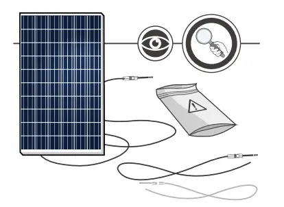
![]() Please read these instructions carefully before proceeding with your installation.
Please read these instructions carefully before proceeding with your installation.
![]() Please retain these instructions for the life of the solar modules.
Please retain these instructions for the life of the solar modules.
![]() Please ensure that this Manual is available to the operator at all times.
Please ensure that this Manual is available to the operator at all times.
![]() This Manual should be given to all subsequent owners or users of the solar modules.
This Manual should be given to all subsequent owners or users of the solar modules.
![]() All supplements received from the manufacturer should be included.
All supplements received from the manufacturer should be included.
![]() Please observe all other applicable documents.
Please observe all other applicable documents.
![]() If your questions are not satisfactorily answered in the manual, please contact your system supplier.
If your questions are not satisfactorily answered in the manual, please contact your system supplier.
Additional information can be found on our website at www.qcells.com.
Intended use
This manual is valid for Africa, Asia, Europe, Latin America, South America. These instructions contain information regarding the safe handling and use of quality crystalline solar modules from Qcells and their installation, mounting, wiring, maintenance and disposal.
Symbols and Labels
The following symbols and labels are used throughout the Manual for ease of use.
| Procedure with one or more steps. | |
| Lists of items. | |
| Ensure that when carrying out a procedure, you check the results of said procedure. | |
| Prohibited. | |
| Beware of possible danger or damage. Categories: ■ Danger: Risk of fatal injury ■ Attention: Risk of serious injury or damage to property ■ Note: Risk of damage to product |
Safety Regulations
In particular the installer as well as the operator of a module is responsible for compliance with all applicable statutory requirements and regulations.
![]() Unless otherwise specified by any laws or regulations, the following stipulations must be upheld at all times during the installation, operation, and maintenance of the solar modules:
Unless otherwise specified by any laws or regulations, the following stipulations must be upheld at all times during the installation, operation, and maintenance of the solar modules:
- This manual.
- Other applicable stipulations (such as country-specific regulations for pressure equipment, operational safety, hazardous goods, and environmental protection).
- Regulations and requirements specific to the system.
- Any applicable laws and requirements, in particular international, country specific, regional laws and stipulations governing the planning, installation, and operation of solar power systems and work on roofs.
- Any valid international, national and regional regulations governing work with direct current, especially those applicable to the installation of electrical devices and systems, and regulations issued by the respective energy provider governing the parallel operation of solar power systems.
- Any international, country specific and regional accident prevention regulations.
- Other applicable stipulations provided by the relevant national institutions regarding safety in the installation and operation of electrical items.
Qualified and Skilled Personnel
Both, the installer and operator are responsible for ensuring that the installation (including connection to the grid), maintenance and dismantling are carried out by trained and qualified specialists with approved training certificates (issued by a state or federal organization) for the respective specialist trade. Electrical work may only be performed by an officially certified tradesperson in accordance with the stipulations applicable in the relevant country with regard to standard and regulations (in Germany e. g. DIN standards, VDE regulations) and the stipulations of the local grid operator and/or energy provider.
Validity
These instructions are only valid for crystalline solar modules from the company Qcells as specified at chapter “2.1 Technical specifications”. Qcells assumes no liability for damage resulting from failure to observe these instructions.
![]() Please observe the wiring and dimensioning of the system.
Please observe the wiring and dimensioning of the system.
![]() The installer of the system is responsible for compliance with all necessary safety regulations during set-up and installation.
The installer of the system is responsible for compliance with all necessary safety regulations during set-up and installation.
Qcells assumes no liability on the basis of these instructions. Qcells is only liable in the context of contractual agreements or in the context of accepted guarantees. Qcells accepts no other responsibility for the functionality and safety of the modules.
![]() Please observe the instructions for any other system components that may be part of the complete solar power system. It may be necessary to carry out a structural analysis for the entire project.
Please observe the instructions for any other system components that may be part of the complete solar power system. It may be necessary to carry out a structural analysis for the entire project.
Additional information for the Operator
![]() Please keep this manual for the entire life of the solar power system.
Please keep this manual for the entire life of the solar power system.
![]() Please contact your system supplier for information concerning the formal requirements for solar power systems.
Please contact your system supplier for information concerning the formal requirements for solar power systems.
![]() Please be sure to contact the relevant local authorities and energy providers regarding regulations and permit requirements prior to installation of the solar power system. Your financial success depends on the fulfillment of these requirements.
Please be sure to contact the relevant local authorities and energy providers regarding regulations and permit requirements prior to installation of the solar power system. Your financial success depends on the fulfillment of these requirements.
Other applicable documents
In addition to this Manual following technical information are relevant:
Document type
Product data sheet
Packaging and transport information
MISUSE OR INCORRECT USE OF SOLAR MODULES VOIDS THE LIMITED WARRANTY AND MAY CREATE A SAFETY HAZARD AND RISK PROPERTY DAMAGE. THIS INCLUDES IMPROPER INSTALLATION OR CONFIGURATION, IMPROPER MAINTENANCE, UNINTENDED USE, AND UNAUTHORIZED MODIFICATION.
![]() Attention!
Attention!
This marking indicates that this product should not be disposed of with other household waste within the EU. Recycle this product properly to prevent possible damage to the environment or a risk to human health via uncontrolled waste disposal and in order to promote the sustainable reuse of material resources. Please return your used product to an appropriate collection point or contact the retailer where you purchased this product. Your retailer will accept used products and return them to an environmentally-sound recycling facility.
Planning
2.1 Technical specifications
For additional information see the relevant datasheet of the module provided at www.qcells.com.
| PRODUCT LINE | Q.PEAK DUO M-G11 Q.PEAK DUO M-G11+ |
Q.PEAK DUO BLK M-G11 Q.PEAK DUO BLK M-G11+ |
| Type | Q.ANTUM DUO Z | |
| Length | 1692mm | |
| Width | 1134 mm | |
| Frame height | 30 mm | |
| Area | 1.92 m² | |
| Weight | 21.2 kg | |
| Max. system voltage VSYS | 1000 V | |
| Max. reverse current | 25 A | |
| Permissible temperature range | –40 °C to +85 °C (–40 °F to +185 °F) | |
| Junction box protection class | IP67 with bypass diode | |
| Connector protection class | IP68 | |
| Fire rating based on ANSI / UL 61730 | C / Type 2 | |
| Max. test load Push / Pull1 | 5,400 Pa / 3,600 Pa | |
| Max. design load Push / Pull1 | 3,600 Pa / 2,400 Pa | |
| Certificates | CE-compliant; IEC 61215:2016; IEC 61730:2016; PV module classification: Class II; QCPV | |
| 1 Test and design load in accordance with IEC 61215:2016, depending on mounting options (see section “2.3 Mounting options”) | ||
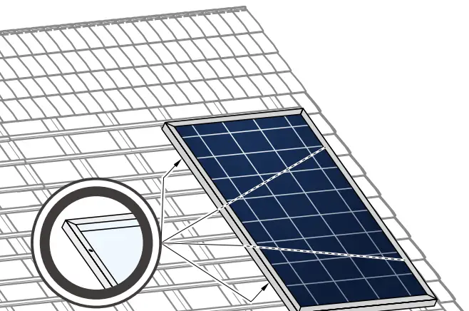
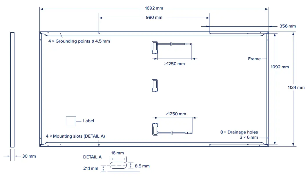 Fig. 1: External dimensions and components for
Q.PEAK DUO M-G11/Q.PEAK DUO BLK M-G11/Q.PEAK DUO M-G11+/Q.PEAK DUO BLK M-G11+
2.2 Requirements
Installation Site
Please note the following guidelines that apply to the installation site:
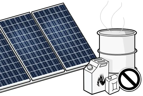
■ Solar modules are not explosion-proof and are not suitable for use in explosive environments.
![]() Do not operate solar modules near highly flammable gas and vapors (e.g. gas tanks, gas stations).
Do not operate solar modules near highly flammable gas and vapors (e.g. gas tanks, gas stations).
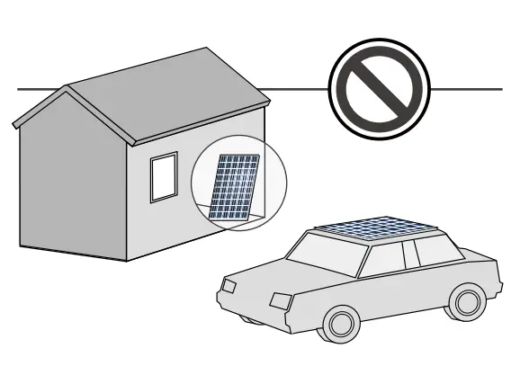
![]() Do not install modules in enclosed space.
Do not install modules in enclosed space.
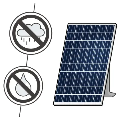
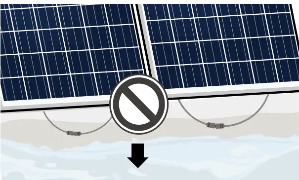
![]() Do not install modules in locations where they may be submerged in water (e.g. floodplains).
Do not install modules in locations where they may be submerged in water (e.g. floodplains).
![]() Do not use modules as a substitute for the normal roofing (e.g. modules are not watertight).
Do not use modules as a substitute for the normal roofing (e.g. modules are not watertight).
![]() Do not install modules in close proximity to air conditioning systems.
Do not install modules in close proximity to air conditioning systems.
![]() Do not install modules above 4000 m (13120 ft) altitude above sea level.
Do not install modules above 4000 m (13120 ft) altitude above sea level.
![]() Contact with saline water (e.g. spray water from the sea) and salt aggregation on the modules must be avoided.
Contact with saline water (e.g. spray water from the sea) and salt aggregation on the modules must be avoided.
![]() Do not bring any chemical substance (e.g. oil, solvent etc.) into contact with any part of the panel. Only substances, which are released by Qcells, are allowed to be used during installation, operation and maintenance.
Do not bring any chemical substance (e.g. oil, solvent etc.) into contact with any part of the panel. Only substances, which are released by Qcells, are allowed to be used during installation, operation and maintenance.
![]() Any installation of modules on surfaces of water is prohibited. This includes installations on floating as well as pile-based platforms. Qcells may extend the coverage of its warranty to such installations, based on a case by case assessment of the system design and location. A prior written consent by the warrantor is required in any case.
Any installation of modules on surfaces of water is prohibited. This includes installations on floating as well as pile-based platforms. Qcells may extend the coverage of its warranty to such installations, based on a case by case assessment of the system design and location. A prior written consent by the warrantor is required in any case.
The solar modules are designed for the following applications:
- Operating temperatures from –40 °C to +85 °C (–40 °F to +185 °F).
- Pull loads up to max. 3,600 Pa and push loads up to max.5,400 Pa (see chapter “Mounting options”).
- Installation using a mounting structure for solar modules.
Prevention of Shadowing Effects
Optimal solar irradiation leads to maximum energy output:
![]() For this reason, install the modules so that they face the sun.
For this reason, install the modules so that they face the sun.
![]() Avoid shadowing (due to objects such as buildings, chimneys or trees).
Avoid shadowing (due to objects such as buildings, chimneys or trees).
![]() Avoid partial shading (for example through overhead lines, dirt, snow).
Avoid partial shading (for example through overhead lines, dirt, snow).
Mounting Structure Requirements
The Modules shall be installed and operated on mounting structures that comply with any applicable laws and stipulations as well as with the following:
- Conform to the necessary structural requirements.
- Compliant with local snow and wind loads.
- Properly fastened to the ground, the roof, or the façade.
- Forces acting on the module are relayed to the mounting substructure.
- Ensures sufficient rear ventilation of the module.
- Avoid the usage of different metals to prevent contact corrosion.
- Allows for stress-free expansion and contraction due to temperature fluctuations.
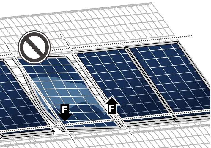
![]() Ensure that no additional forces are applied through the mounting system into the module except for the wind and snow loads. Additional forces and moments of torque at the mounting positions caused by torsions, displacements or vibrations in the mounting system are not allowed.
Ensure that no additional forces are applied through the mounting system into the module except for the wind and snow loads. Additional forces and moments of torque at the mounting positions caused by torsions, displacements or vibrations in the mounting system are not allowed.
![]() Ensure that the clamps and the mounting frame are compatible.
Ensure that the clamps and the mounting frame are compatible.
Clamp System Recommendations
Use customary clamps that satisfy the following requirements:
- Clamp width: ≥ 40 mm.
- Clamp height compliant with a 30 mm frame height.
- Clamp depth: 7-12 mm. (applicable for all CL clamping mounting options at section “2.3 Mounting options”)
- Clamps are not in contact with the front glass.
- Clamps do not deform the frame.
- Clamps that satisfy the structural requirements based on the conditions of the installation site according to the applicable regulations and technical standards.
- Long-term stable clamps that securely affix the module to the mounting frame.
Module Orientation Requirements
- Vertical or horizontal installation is permitted.
![]() Ensure that rain and melting snow can run off freely. No water accumulation.
Ensure that rain and melting snow can run off freely. No water accumulation.
![]() Ensure that the drainage holes in the frame are not covered. No sealing.
Ensure that the drainage holes in the frame are not covered. No sealing.
![]()
![]() Maintain the permissible angle of inclination.
Maintain the permissible angle of inclination.
- Minimum angle of inclination: 3°
- Inclination angles above 75° may be limited by local regulations
![]() Standing water on the modules glass needs to be avoided.
Standing water on the modules glass needs to be avoided.

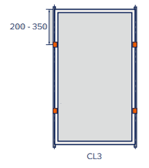
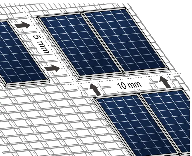
2.3 Mounting options
Fig. 2: Installation options for crystalline Qcells modules. All dimensions are given in mm. Also observe the maximum test loads and clamping range as specified on the following page.
The illustrated installation options apply for both horizontal and vertical module orientation.
 |
Module |  |
Sub construction |
 |
Clamp |  |
Mounting profile |
| TYPE OF INSTALLATION | POINT MOUNTING SYSTEM | LINEAR MOUNTING SYSTEM |
| Installation with clamps | 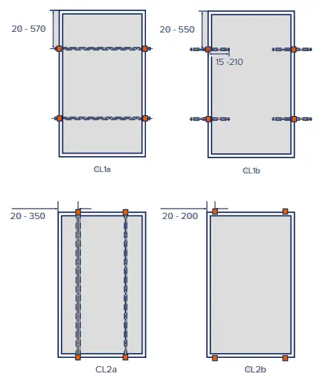 |
 |
| Hybrid clamping |  |
|
| Installation on mounting points |  |
 |
| Installation with insertion profiles | not permitted |  |
Specifications
| MOUNTING OPTION | POSITION OF CLAMPS* [MM] | TEST LOAD PUSH/PULL** [Pa] | DESIGN LOAD PUSH/PULL** [Pa] | SAFETY FACTOR |
| CL1a | 100 – 450 | 5400 / 3600 | 3600 / 2400 | 1.5 |
| 20 – 570 | 2400 / 2400 | 1600 / 1600 | ||
| CL1b | 200 – 350 | 2400 / 3300 | 1600 / 2200 | |
| CL2a | 20 – 150**** | 2400 / 2400 | 1600 / 1600 | |
| CL2b | 20 – 200 | 2400 / 2400 | 1600 / 1600 | |
| CL3 | 200 – 350 | 3600 / 3600 | 2400 / 2400 | |
| CL5 | short side: 20 – 100 long side: 300 – 450 |
3000 / 3000 | 2000 / 2000 | |
| FB1 | 356 | 5400 / 3600 | 3600 / 2400 | |
| FB2 | 356 | 3000 / 3000 | 2000 / 2000 | |
| IP1 | – |
![]() The below mounting options are only possible under certain conditions.
The below mounting options are only possible under certain conditions.
| MOUNTING OPTION | POSITION OF CLAMPS* [MM] | TEST LOAD PUSH/PULL*** [Pa] | DESIGN LOAD PUSH/PULL*** [Pa] | SAFETY FACTOR |
| CL1b | 20 – 550 | 1600 / 2400 | 1060 / 1600 | 1.5 |
| CL2a | 20 – 350**** | 2400 / 2000 | 1600 / 1330 | |
| IP2 | – | 2400 / 1800 | 1600 / 1200 | |
| * Distance between outer edge of module and middle of the clamp; consider further details below. ** Loads according to IEC 61215-2:2016 and UL 61730-2:2020 *** Test procedure according to IEC 61215-2:2016 and UL 61730-2:2020. Loads for these mounting options do not fulfill the requirements of the standards. **** Rails must not be under the junction box. |
||||
| MOUNTING OPTION | REQUIREMENTS |
| All | |
| CL1a, CL2a, CL3, FB1, FB2 | |
| CL1b | |
| CL1b, CL2b, CL3, FB2 | |
| CL5 | |
| IP1, IP2 | |
| FB1, FB2 |
2.4 Electrical layout
Module Selection
For detailed key electrical data, please refer to the actual data sheet referring to the relevant Module (available at www.qcells.com).
For maximum energy yields, mismatches of specified electric current (IMPP) of more than 5 % should be avoided for all modules connected in series.
Safety Factor
For detailed key electrical data, please refer to the actual data sheet referring to the relevant Module (available at www.qcells.com).
- During normal operation, a module may generate a greater current and/or higher voltage than that determined under standardized test conditions. Please use a safety factor of 1.25 for the following:
Calculating the voltage measurement values (VOC) of components
- Calculating the current measurement values (ISC) of conductors
- Sizing of control systems connected to the outlets of the solar modules
![]() Please follow the valid national guidelines for the installation of electrical systems.
Please follow the valid national guidelines for the installation of electrical systems.
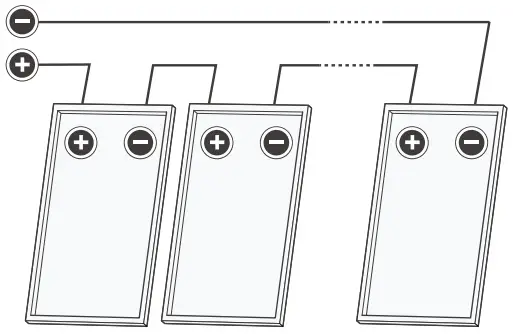
Series Connection
Connection of modules in series is only permitted up to the maximum system voltage as listed in the applicable data sheet of all the relevant modules to be installed.
![]() Take into account all possible operating situations and all relevant technical norms and regulations when designing the system. It has to be ensured that the maximum system voltage, including all necessary safety margins, is not exceeded.
Take into account all possible operating situations and all relevant technical norms and regulations when designing the system. It has to be ensured that the maximum system voltage, including all necessary safety margins, is not exceeded.
![]() Take the voltage limit of the inverter into account when determining the maximum number of modules in the string.
Take the voltage limit of the inverter into account when determining the maximum number of modules in the string.
Parallel Connection
Modules may be damaged by the occurrence of reverse currents (caused by module defects, ground leaks, or defective insulation).
Ensure that the maximum reverse current load capacity indicated in the data sheet is met.
In order to limit reverse currents that may occur, we recommend using the following safety options:
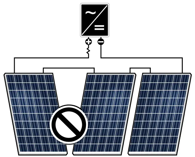
- Layout with a limited number of parallel connected strings :
Without undertaking further current blocking measures, a maximum of two module strings may be operated in parallel on a single inverter or MPP tracker. - Layout with string fuses :
Use overcurrent devices (e.g. fuses) according to the relevant standards in each string. Use gPV-fuses according to IEC 60269-6. Observe the maximum permitted number of strings as indicated in the specifications provided by the respective string fuse manufacturer and the technical guidelines.
NOTE!
When installing different product versions, the lowest minimum permitted reverse current load capacity applies.
Inverters
Inverters with or without transformers may be used.
Installation
3.1 Safety and transport
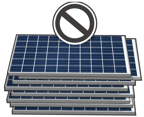
 |
 |
 |
 |
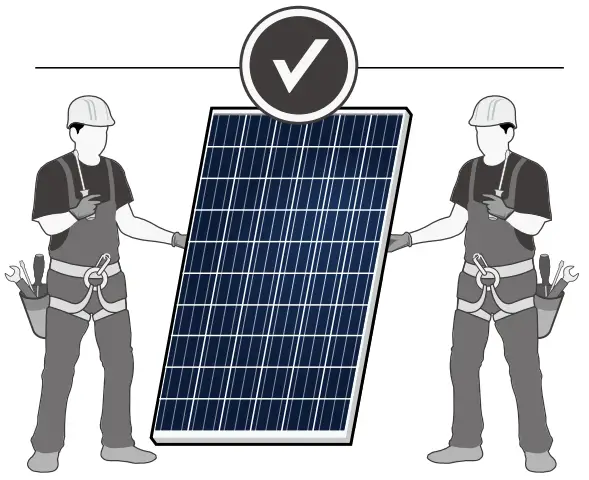
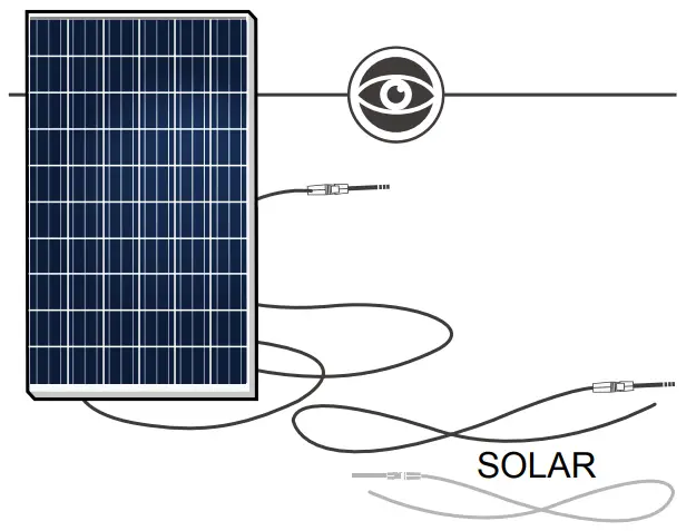
Never lift or move the module with the connection cables or junction box. |
|
 |
 |
 |
 |
 |
 |
 |
|
3.2 Preparation of installation
 |
 |
 |
 |
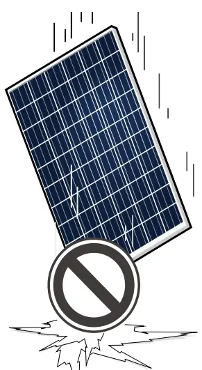
■ Only install undamaged modules and components. (e.g. do not drill any additional holes). |
|
 |
 |
3.3 Module installation
 |
|
 |
|
 |
|
 |
|
 |
Electrical connection
4.1 Safety
Danger!
Risk of fatal injury due to electric shock!
When disconnecting an electric circuit carrying direct current, electric arcs can occur that may result in life-threatening injuries.
![]() Do NOT unplug the cable when under load.
Do NOT unplug the cable when under load.
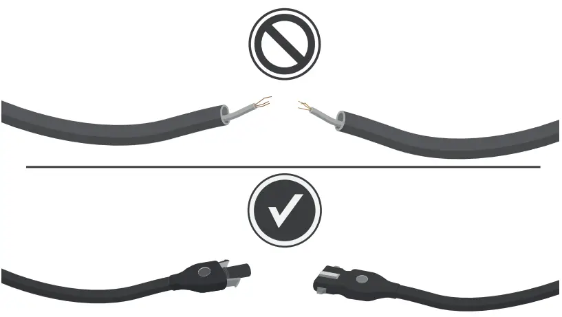
![]() Do NOT connect any exposed cable ends.
Do NOT connect any exposed cable ends.
![]() Electrical work may only be performed by qualified and skilled personnel (see page 3).
Electrical work may only be performed by qualified and skilled personnel (see page 3).
A solar module generates electrical current and voltage even at a low intensity of illumination. Sparks and electric arcs may result from the separation of a closed circuit. These can result in life-threatening injuries. The danger increases when several modules are connected in series.
![]() Please be aware of that the entire open circuit voltage is active even at low levels of solar irradiation.
Please be aware of that the entire open circuit voltage is active even at low levels of solar irradiation.
![]() Please follow the valid national regulations and safety guidelines for the installation of electrical devices and systems.
Please follow the valid national regulations and safety guidelines for the installation of electrical devices and systems.
![]() Please make sure to take all necessary safety precautions. With module or phase voltages of more than 120 V, the safety extralow voltage range is exceeded.
Please make sure to take all necessary safety precautions. With module or phase voltages of more than 120 V, the safety extralow voltage range is exceeded.
![]() Carry out work on the inverter and the wiring with extreme caution.
Carry out work on the inverter and the wiring with extreme caution.
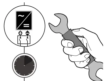
![]() Ensure that the modules are disconnected at the inverter prior to separation.
Ensure that the modules are disconnected at the inverter prior to separation.
![]() Be sure to observe the time intervals specified by the inverter manufacturer after switching off the inverter.
Be sure to observe the time intervals specified by the inverter manufacturer after switching off the inverter.
![]() Make sure that the plugs can not be connected unintentionally.
Make sure that the plugs can not be connected unintentionally.
![]() Before working on the contacts, check them for safety extralow voltage.
Before working on the contacts, check them for safety extralow voltage.
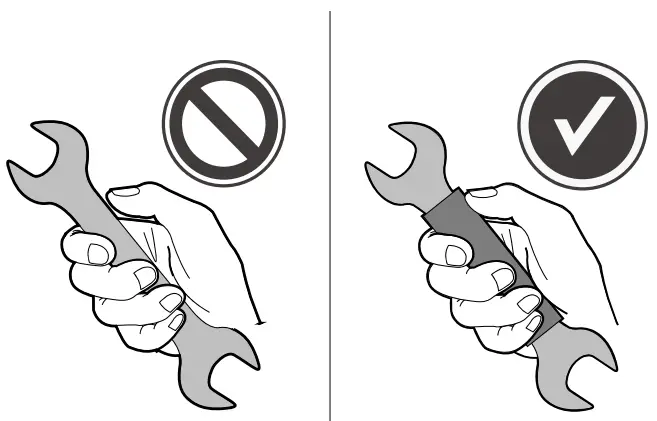
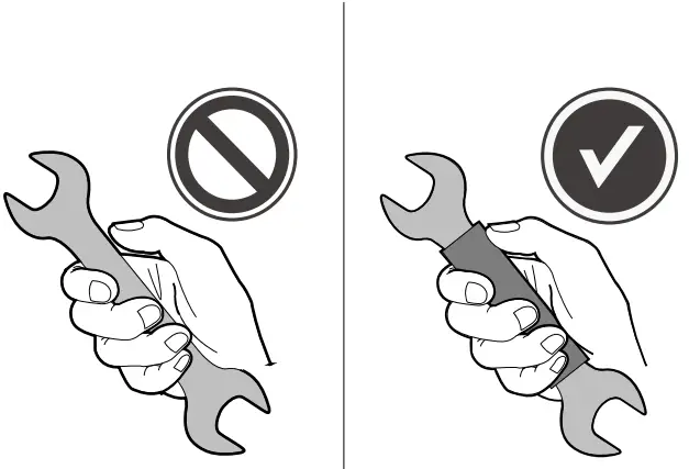
Only use dry, insulated tools for electrical work. |
|
 |
 |
 |
 |
4.2 Electrical installation safety
 |
 |
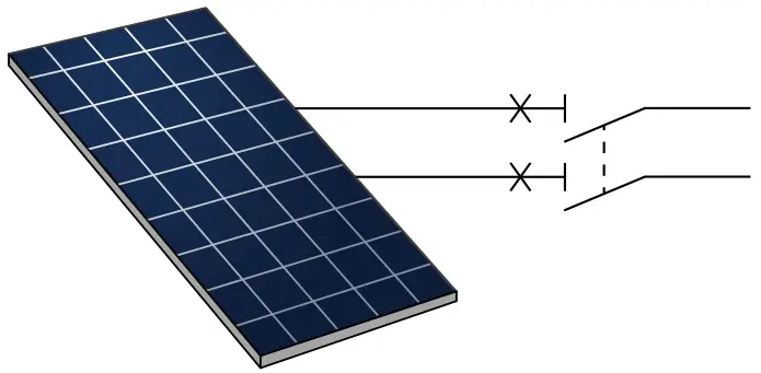
1. Switch off the inverter. |
3. Measure shutdown in DC String. (no DC current flow). 4. Disconnect plugs by the use of appropriate and qualified tools of the manufacturer. 5. When connecting the modules proceed in reverse order. |
 |
 |
4.3 Connection of modules
 |
 |
 |
 |
 |
 |
4.4 After installation
 |
|
 |
|
 |
|
 |
|
 |
Grounding
Protective Grounding
![]() The modules must be grounded in accordance with the local statutory regulations.
The modules must be grounded in accordance with the local statutory regulations.
Faults and defects
![]() Danger!
Danger!
Risk of fatal injury due to electric shock!
![]() Do not attempt to fix any problems yourself (e.g., glass cracks, damaged cables).
Do not attempt to fix any problems yourself (e.g., glass cracks, damaged cables).
![]() Please contact an installer or Qcells Technical Customer Service Department.
Please contact an installer or Qcells Technical Customer Service Department.
Disposal
![]() Do not disconnect modules by yourself.
Do not disconnect modules by yourself.
![]() Please contact an installer or Qcells Technical Customer Service Department.
Please contact an installer or Qcells Technical Customer Service Department.
![]() Dispose of modules in accordance with the local disposal regulations.
Dispose of modules in accordance with the local disposal regulations.
Maintenance and cleaning
Qcells solar modules are known for a long operating life and minimal maintenance effort and expense. Dirt and grime are usually washed away by rain. If the module is fully or partially shaded by dirt or debris (e.g., plants, bird droppings), it needs to be cleaned to prevent a loss of performance.
Maintenance
![]() The PV system has to be inspected regularly by certified personnel
The PV system has to be inspected regularly by certified personnel
![]() The time intervals and extent of the inspection can depend on local circumstances (e.g. salt, ammonia content in the air, high humidity etc.). The customer / operator must inform himself about time intervals and extend of necessary inspections.
The time intervals and extent of the inspection can depend on local circumstances (e.g. salt, ammonia content in the air, high humidity etc.). The customer / operator must inform himself about time intervals and extend of necessary inspections.
![]() Inspections have to be performed especially after extraordinary events (e.g. storm, hail, high snow loads etc.)
Inspections have to be performed especially after extraordinary events (e.g. storm, hail, high snow loads etc.)
![]() During the inspections it has to be checked that the components are secure, undamaged and clean
During the inspections it has to be checked that the components are secure, undamaged and clean
Cleaning
![]() WARNING!
WARNING!
Risk of injury due to hot and live modules!
![]() Only clean modules that have cooled down.
Only clean modules that have cooled down.
![]() Do not carry or wear any electrically conductive parts.
Do not carry or wear any electrically conductive parts.
![]() WARNING!
WARNING!
Risk of falling due to unsecured access!
![]() Never access the installation area alone or without taking adequate security precautions.
Never access the installation area alone or without taking adequate security precautions.
![]() Please commission a trade specialist.
Please commission a trade specialist.
![]() NOTE!
NOTE!
Module surface damage may occur!
![]() Remove snow and ice carefully without force (e.g. with a very soft broom).
Remove snow and ice carefully without force (e.g. with a very soft broom).
![]() Do not scratch off dirt.
Do not scratch off dirt.
![]() Module cleaning has to be done by qualified personnel according to the state of the art and taking into account all relevant safety issues and general product properties, e.g., but not restricted to:
Module cleaning has to be done by qualified personnel according to the state of the art and taking into account all relevant safety issues and general product properties, e.g., but not restricted to:
- electrical safety
- mechanical stability (load limits depending on the actual mounting options)
- chemical suitability (no effect to any of the module‘s components, e.g. cable, connector, silicone)
- no abrasive materials.
![]() NOTE!
NOTE!
Dust and dirt are abrasive materials!
![]() The situation for each individual project (or type of dirt) must always be professionally evaluated.
The situation for each individual project (or type of dirt) must always be professionally evaluated.
![]() Wrong cleaning may cause damages such as, but not limited to, damages to the glass surface (e.g. scratches) and AR coating, power loss, delamination, loss of frame-to-laminate bond, reduced snow and wind load capability etc.
Wrong cleaning may cause damages such as, but not limited to, damages to the glass surface (e.g. scratches) and AR coating, power loss, delamination, loss of frame-to-laminate bond, reduced snow and wind load capability etc.
Apart from the above, each customer is free to choose the method of cleaning. However, possible damages, caused by the cleaning or related to the cleaning tools or agents shall not be covered by the module‘s Product and Performance Warranty. Therefore it is recommended to use only the tools and agents which have already been successfully tested and used with PV modules, to prevent possible damage.
Isopropyl alcohol (IPA) can be used selectively to remove stubborn dirt and stains within one hour after emergence.
 |
 |
![]() Hanwha Q CELLS GmbH
Hanwha Q CELLS GmbH
OT Thalheim Sonnenallee 17 – 21 06766 Bitterfeld-Wolfen Germany
EMAIL: [email protected]
WEB: www.qcells.com
TEL: +49 (0)3494 66 99 – 23222
FAX: +49 (0)3494 66 99 – 23000
Subject to change without notice.
© Qcells Installation manual solar modules Q.PEAK_DUO_M-G11.X_modules_series_30T_2022-07_Rev04_EN