![]() INSTALLATION INSTRUCTIONS
INSTALLATION INSTRUCTIONS
PT-BLP6-3CP (EM) SERIES
PT-BLP6-24 / PT-BLP6-22 / PT-BLP6-14

![]()
Contents
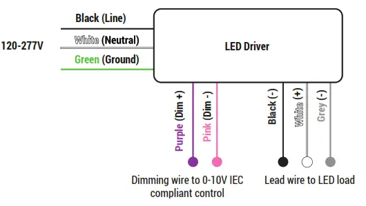
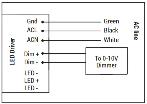
GENERAL WIRING DIAGRAM
WARNING
- TO REDUCE THE RISK OF DEATH, PERSONAL INJURY OR PROPERTY DAMAGE FROM FIRE, ELECTRIC SHOCK, FALLING PARTS, CUTS/ABRASIONS, AND OTHER HAZARDS READ ALL WARNINGS AND INSTRUCTIONS INCLUDED WITH AND ON THE FIXTURE BOX AND ALL FIXTURE LABELS.
- BEFORE INSTALLING, SERVICING, OR PERFORMING ROUTINE MAINTENANCE UPON THIS EQUIPMENT, FOLLOW THESE GENERAL PRECAUTIONS.
- COMMERCIAL INSTALLATION, SERVICE AND MAINTENANCE OF LUMINAIRES SHOULD BE PERFORMED BY A QUALIFIED LICENSED ELECTRICIAN.
- FOR THE INSTALLATION: IF YOU ARE UNSURE ABOUT THE INSTALLATION OR MAINTENANCE OF THE LUMINAIRES, CONSULT A QUALIFIED LICENSED ELECTRICIAN AND CHECK YOUR LOCAL ELECTRICAL CODE.
- TO PREVENT WIRING DAMAGE OR ABRASION, DO NOT EXPOSE WIRING TO EDGES OF SHEET METAL OR OTHER SHARP OBJECTS.
- DO NOT MAKE OR ALTER ANY OPEN HOLES IN AN ENCLOSURE OF WIRING OR ELECTRICAL COMPONENTS DURING KIT INSTALLATION.
WARNING
- TURN OFF ELECTRICAL POWER AT FUSE OR CIRCUIT BREAKER BOX BEFORE WIRING FIXTURE TO THE POWER SUPPLY.
- TURN OFF THE POWER WHEN YOU PERFORM ANY MAINTENANCE.
- VERIFY THAT SUPPLY VOLTAGE IS CORRECT BY COMPARING IT WITH THE LUMINAIRE LABEL INFORMATION.
- ALL WIRING CONNECTIONS SHOULD BE CAPPED WITH UL APPROVED WIRE CONNECTORS.
CAUTION
- AVOID DIRECT EYE EXPOSURE TO THE LIGHT SOURCE WHILE IT IS ON.
- ACCOUNT FOR SMALL PARTS AND DESTROY PACKING MATERIAL, AS THESE MAY BE HAZARDOUS TO CHILDREN.
- RISK OF BURN. DISCONNECT POWER AND ALLOW FIXTURE TO COOL BEFORE CHANGING BULB OR HANDING FIXTURE.
INSTALLATION
(ALWAYS TURN OFF THE POWER SUPPLY FROM MAIN CIRCUIT BREAKER FIRST!)
- Carefully unpack unit and properly inspect for defects before installing. Wear work gloves to prevent dirt and oil from being transferred to the luminaire. If cleaning is needed, use gloves and a dry cotton cloth. It is not recommended to use hazardous chemicals.

- Lift up four mounting clips on the sides of the luminaire. You can do it by hand (Do wear work gloves) or use pliers.

- Insert luminaire into T-bar ceiling grid. Secure safety cable to connection hole as needed to meet local seismic requirements. Safety cable and method of attachment to the building provided by contractor according to local building codes.

- Remove electrical enclosure cover. Carefully remove knockout for AC line input wires and 0-10V control line. Install listed electrical fittings in the knockout holes for wire protection if needed.
- Plug in AC line(L and N,and GND) to the LED Driver using 18-14AWG Wire. When connecting 0-10Vdimming controller, wires must run through a separate knockout hole equipped with an appropriate electrical fitting.

- Follow wire connection instructions. When using the 0-10V dimming controller Run wires from controller through a different knockout than the AC input wire. Don t forget to return the electrical enclosure cover and tighten the screws.
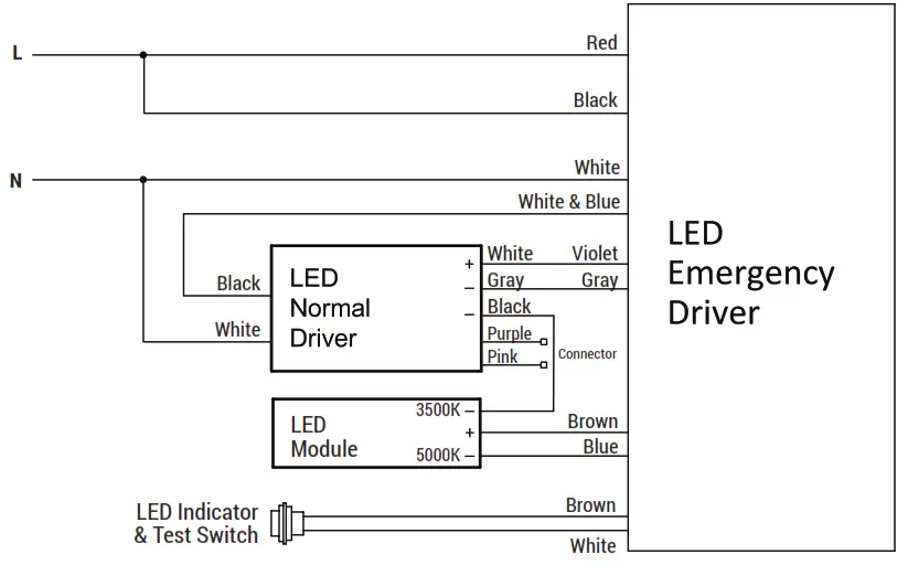
EMERGENCY BATTERY BACK-UP

WIRING DIAGRAM
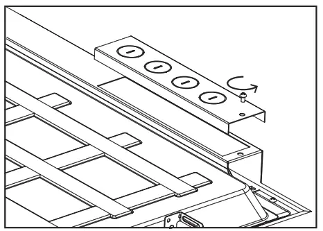
CCT TUNABLE AND WATTAGE SELECTOR
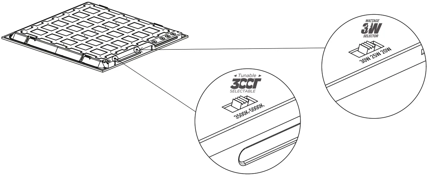
FACTORY SETTINGS: 5000K @ 25W
- DIP switches are located onto the drive box.
- Select a wattage and color temperature by sliding switch left or right respectively to the desired value.
![]() www.portorlighting.com
www.portorlighting.com
Specification subject to change without notice