![]() WiFi 2.4G RJ45 D WiFi Adapter
WiFi 2.4G RJ45 D WiFi Adapter
Instruction Manual
Contents
WiFi 2.4G RJ45 D WiFi Adapter
※ Thank you for selecting this WiFi 2.4G RJ45 D adapter; please read this manual carefully before using the product.
※ Do not install the product in humid, salt spray, corrosion, greasy, flammable, explosive, dust accumulative, or other severe environments.
WiFi Adapter
WiFi 2.4G RJ45 D
Overview
Through a local 2.4G WiFi network, the WiFi 2.4G RJ45 D can transmit all operational data from the solar controller, inverter, or inverter/charger to the cloud server in real-time.
Users can remotely monitor connected devices and program parameters via the server platform and mobile app.
Features
- Suitable for controllers, inverters, or inverter-chargers with RJ45 port
- Can be used immediately after connecting, with easy and convenient operation
- Directly powered by the communication port
- Up to 20 meters of communication distance
- Supports the “Local” monitoring and “Cloud” working modes.
Appearance

- RJ45 connector: Connect to the RJ45 port of the controller, inverter, or inverter/charger. RJ45 Pin Definition:
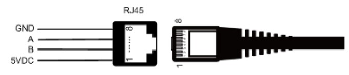
| Pin | Definition |
| 1 | +5VDC |
| 2 | +5VDC |
| 3 | RS485-B |
| 4 | RS485-B |
| 5 | RS485-A |
| 6 | RS485-A |
| 7 | GND |
| 8 | GND |
Specifications
| Model Parameter | WiFi 2.4G RJ45 D |
| Working voltage | 5V± 0.5V(Powered by RS485 com. port) |
| Power consumption | Peak: 150mA; Idle: 310uA |
| Enclosure | IP30 |
| Communication method | RS485 |
| Communication parameters | 115200Bps, 8N1 |
| Interface standard | Communication standard V1-1.0 |
| Work frequency | 2.4 ~ 2.4835 GHz |
| Work temperature range | -40℃~ 85℃ |
| Dimension | 63mm x 19mm x 10mm |
| Net weight | 7.7g |
Note: The WiFi adapter working voltage is 4.5V~5.5V and peak consumption is 150mA, so it is only suitable for devices that meet this requirement.
Working processes

- Connect the WiFi adapter to the RJ45 port of the device. ② Add the WiFi adapter into the cloud by the PC or mobile app. WARNING: The WiFi adapter is not compatible with the PU1024B/PU2024B, PU1024BW/PU2024BW and LS-B series controllers. If
the WiFi adapter is installed in a metal cabinet, the signal strength and distance will be reduced, depending on the material and size of the cabinet.
Scenario 1: There is a local 2.4G WiFi network. The WiFi adapter can upload the collected data to the cloud automatically.
Step1: Turn on the WiFi switch on the mobile phone, and connect to the local WiFi network (a 2.4G WiFi network is a must).
 |
|
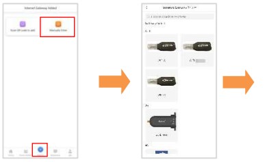
| Step2: Log into the app and click the icon to add a new gateway. | Step3: Select the gateway model. |
 |
|
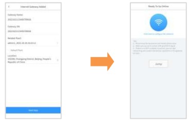
| Step4: Input the gateway data (“Gateway SN” is the 22-digit number of the gateway WiFi name), and click “Next Step” to enter the device adding page. |
Step5: After adding the device, click “Next Step” to enter the above page. |
 |
|
| Step6: Input the local WiFi password and click “Next Step.” |
Step7: Click “Go to set up Wi-Fi” to connect phone to the gateway WiFi (HN_EPSN: xxxxxx,password:12345678). Return to the app after connection, and click “Next Step.” |
Scenario 2: There is no local 2.4G WiFi network. The WiFi adapter cannot upload the collected data to the cloud.
 |
|
| Step1: Login to the app and click “My>Collect Data. ” Select all products and click “Synchronize data” to download data. |
Step2: After all data is downloaded, return to the app. Click “Home > Offline.” |
 |
|
| Step3: Select the module type (WIFI) | Step4: Turn on the phone WiFi switch and connect the phone to the gateway WiFi(HN_EPSN: xxxxxx, password: 12345678). |
 |
|
| Step5: Return to the app and click “Equipment>Add equipment” (“Gateways” is the 22-digit number of the gateway WiFi name).Click “Confirm” to add the device. |
Step6: On the “Device List” page, click the gateway SN to enter the device’s real-time monitoring page. |
![]() Please note that changes can be made without prior notice.
Please note that changes can be made without prior notice.
Version number: V1.1