PHENYX PRO PTM-10 Stereo and Mono Mode Professional UHF Wireless In Ear Monitor System Owner’s Manual
Contents
System Description
System overview
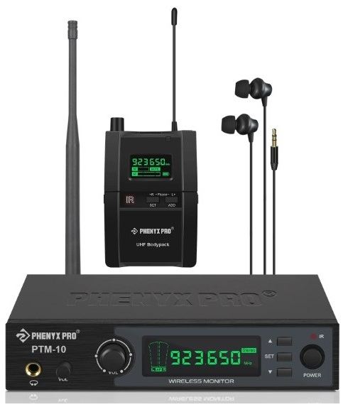
The Phenyx Pro PTM-10 passes the right of sound monitoring into your hands. It is a practical solution to block out excess stage noise and provide consistent sound wherever you go on stage, enabling stage arrangement, increasing freedom of movement, and enhancing sound performance. This system uses advanced circuit design to make the received signal steady and improve the anti-interfer-ence function to show the perfect original sound. This IEM system features the stereo function to transmit undisturbed and separate mixing sound (up to 93% separation). It recreates a live stage-like immersive listening experience, frees you from wire entanglement, and offers you more options to control sound monitoring, ideal for stages, bands, gigs, studios. etc.
System features
•Clear, pure, distortion-free sound performance. • Painless IR synchronization makes operation a piece of cake.
• 89 adjustable UHF frequency in 900 MHz bands for multiset operation.
• Up to 160ft/50m free operation range.
• The adapter cord tie-off renders manageable cables.
•The powerful receiver features multiple practical functions, including stereo/mono selection, balance, equalizer, limiter, and lock functions
• Metal rackmount kit is included to provide the professional option.
• The black PVC carrying case to protect the system while in transit.
System components
I PMT-1 I In-Ear Monitor Transmitter
Receiver
I PMR-1 I Bodypack Receiver
Accessories
| ANTB-900 | Antennas for 900 UHF Band |
| PTA-01 | Power Adapter |
| PTA-03 | Carrying Case |
| PME-1 | Earphone |
| AA Batteries | |
| Metal Rackmount Kit | |
| User’s Manual |
Function of Parts
Transmitter
PMT-1
- Audio output jack (1/4 Inch TRS): Connect to a headphone, earphone, or wedge speaker for direct monitoring.
- Output level control: Adjust the level of the output audio signal to the audio output jack (1/4 inch TRS, Balanced).
- Input level control: Adjust the level of the input audio signal from microphones, mixers, and other devices.
- LCD display: Displays audio, RF, and system information.
- Set button: Short press (tap) this button for mode selection.
- Up button: Short press (tap) this button for frequency increment and menu setup.
- Down button: Short press (tap) this button for frequency decrement and menu setup.
- IR window: For infrared synchronization setup.
*NOTE: Please short press (tap) the SET button to initiate IR synchronization (LCD shows ” “). Then vertically aim the IR window of the transmitter to that of the receiver for pairing them up. II’ - Power button: Long press it for 2 seconds to power the unit on and off. When it is on, the LCD screen lights up.
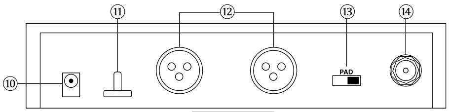
- to Power jack
- Adapter cord tie-off: For managing cable.
- Audio input jacks (XLR, Balanced): Connect to mixer outputs or other audio sources for monitoring by the performers.
- PAD switch: Adjust output gain. Turn it on to cut gain and set it to (-12dB). the default setting of 0dB will have no effect on gain.
Transmitter display
- Antenna jack: For connecting detachable antenna and transmitting signals to bodypack receivers.
- AF signal indicator: For indicating the input audio signal of the left and right channels.
- Frequency number
- Lock indicator: It appears to indicate that the setting is locked and disappears to unlock.
- Mode indicator: For indicating the mono or stereo mode to output the audio signal.
Bodypack receiver
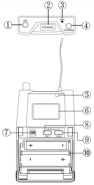
- Volume control: Twist the knob clockwise/counterclockwise to increase/ decrease the volume.
- Power button: Long press it for 2 seconds to power the unit on and off.
- Antenna
- PHONE jack
- Battery light: For indicating the battery status. It lights green to indicate sufficient battery and lights red to indicate low battery.
- LCD display: Displays audio, RF, and system information.
- IR window: For infrared synchronization setup. *NOTE: Please vertically aim the IR window on the bodypack receiver to that of the transmitter for pairing them up.
- SET button: Short press (tap) it to enter menus for BAL function and FOC function. Long press it for 1 second to enter other functions (see page 6 for more details).
- ADD button: Short press (tap) it for menu setup.
- Battery compartment: Install batteries with the correct polarity.
Reveiver display
- Frequency number MRF signal indicator: For indicating
- RF signal strength between the bodypack receiver and transmitter. ” iriFi ri” indicates high RF signal level, and “IRF111-01” indicates low RF signal level (-‘) Audio signal progress bar: It flashes to indicate the
- audio signal level. When it is blank, the bodypack receiver receives no sound.
- MUTE indicator: To indicate that the receiver receives no RF signal. It appears when the bodypack receiver is not paired up with the transmitter successfully.
- Stereo mode indicator: ” sr ” appears to indicate the bodypack receiver receives a stereo audio signal. When it disappears, the bodypack receiver receives a mono audio signal.
- Lock indicator: It appears when the setting is locked and disappears when unlocked.
- Battery indicator: Indicates the real-time battery status.
Operation Guidance
Step 1: Turn on the transmitter
- Connect the antenna to the transmitter via the ANT jack.
- For stereo audio transmission, connect the audio source to the stereo audio input jacks of the transmitter via 6.35mm/XLR cables. For mono transmission, connect to the left audio input jack of the transmitter.
- Turn on other devices. Connect the power supply to the transmitter via the power jack, and long press the power button for 2 seconds to turn it on.
Step 2: Turn on the receiver
- Install fresh batteries with the correct polarity.
- Connect an earphone to the bodypack receiver.
- Long press power buttons to turn on the receiver.
Step 3: Set up the transmitter
Short press (tap) the SET button to enter the transmitter menu and select the desired setting and function, including the group number setting, channel number setting, stereo/mono mode, lock function, and the IR synchronization.
- Group number setting
- hort press (tap) the SET button and select ” Group” on the screen.
- Short press (tap) the ““up and ““down buttons to select the desired group number.
- Channel number setting
- Short press (tap) the SET button and select “Channel” on the screen.
- Short press (tap) the ““up and ““down buttons to select the desired channel number.
*Note: Setting the group number and channel number to select the desired frequency.
- Stereo/mono mode ID Short press (tap) the SET button and select “Mode ” on the screen.
- Short press (tap) the “”up and “”down buttons to select the “Stereo” or “Mono” mode.
- Short press tap the upand sownbutton to select the or mode.
*Note: For stereo monitoring, make sure the ” stereo ” indicators are on for both the transmitter and bodypack receiver. If the ” Stereo ” indicator is absent on the receiver display, the receiver is in the mono mode.
- Lock function
- Short press (tap) the SET button and select “Lock” on the screen.
- Short press (tap) the “”up and ““down buttons to lock (you can see the “ ()” on the screen) or unlock the setting.
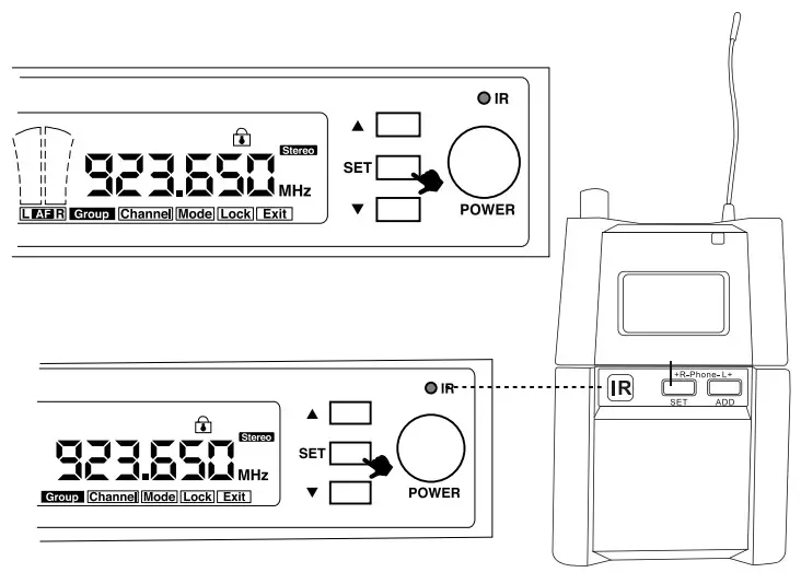
Step 4: Pair up the transmitter and receivers
- Short press (tap) the SET button several times to exit the transmitter menu and initiate the IR synchronization.
- Vertically aim the IR window of a bodypack
receiver to that of the transmitter.
*NOTE: The LCD screens of handheld and bodypack transmitters turn dim in standby mode. The LED light on top of the bodypack transmitter remains green when paired up to indicate it is turned on.
*NOTE: If you would like to use several bodypack receivers simultaneously for monitoring the same audio signal, please pair up all the receivers with the transmitter for the same frequency number.
Step 5: Set up the bodypack receiver
For BAL and FOC functions, short press (tap) the SET button to enter. For other functions, wait back to
the original display (frequency display status), long press the SET button to enter the other functions list, and short press (tap) the SET button to switch functions.
- BAL Function
Balance function. It can adjust the volume of the left/right channel. Each channel has 16 volume settings, including 0, 1, 2, 3, 4, 5, 6, 7, 8, 9, A, B, C, D, E, and F.- When the receiver is in the original display, short press (tap) the SET button to enter the BAL function menu. o__ ma
- Press the SET/ADD button to decrease/increase the volume.
“Note: This function can only be applied when the transmitter and receiver are in stereo mode.
- FOC Function
It can adjust the volume of the left/right channel. Each channel has 16 volume settings, including 0, 2,8, 4,5,6, 7, 8,9, A,B,C, D, E, and F. FJ- When the receiver is in the original display, short press (tap) the SET button to enter the FOC function menu.
- Press the SET/ADD button to decrease/increase the volume.
“Note: This function can only be applied when the receiver is in mono mode.

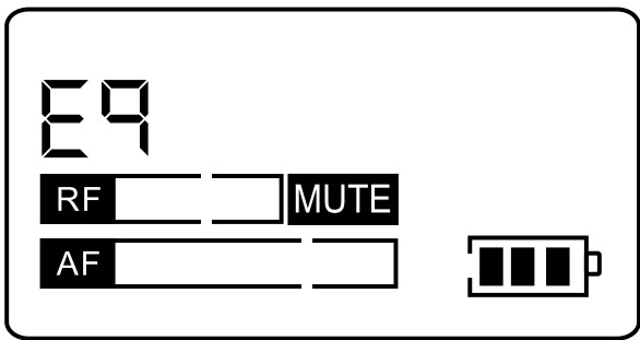
- EQ Function.
Equalizer function, It can adjust the tone/pitch of the music sound, eg- Wait until the receiver is in the original display.
- Long press the SET button to enter the other functions list. ga op
- In the EQ function, press ADD button to select ON/OFF for setting/unsetting.
“Note: When it is in OFF mode, the receiver is in normal mode and would not adjust the tonelpitch of the music, sound regardless of the strength of volume. When itis in ON mode, the receiver isin erease tone/pitch” mode.
- L1 Function
Limiter function. It can attenuate loud audio signals and prevent the sound from being distorted when you turn up the volume too high. However, it changes the music dynamic and might affect the trueness of the sound,- Wait until the receiver is in the original display
- Long press the SET button to enter the other functions list. Short press (tap) to enter the L1 function.
- Press the ADD button, and you can select ON/OFF for setting/unsetting

- FO Function
‘Stereo/mono selection. The stereo/mono mode needs to match the mode selection on the transmitter (base unit),- Wait until the receiver is in the original display
- Long press the SET button to enter the other functions list. Short press (tap) to enter the FO function.
- Press ADD button, and you can select the mono mode (ON) or stereo mode (OFF).
‘Note: The stereo mode is applied when the transmitter and bodypack receivers are both in stereo mode (please check the stereo indicators).
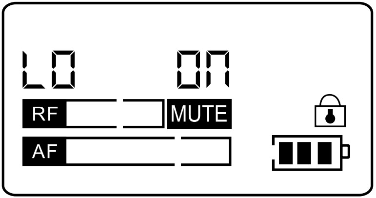
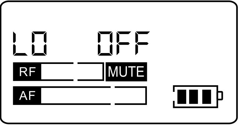
- LO Function
Lock function. Lock the selected frequency on the receiver.- Wait until the receiver is in the original display.
- Long press the SET button to enter the other functions list. Short press (tap) to enter the LO function,
- Press ADD button to select ON/OFF to lock/unlock.
“Note: the lock indicator appears/disappears on the screen when the setting is locked/unlocked.
Troubleshootimg
| Problem | Solution |
| Distorted audio/statics noises |
|
| No sound from a receiver |
|
| High noise floor |
|
| The MUTE indicator on the receiver display after synchronization |
|
| Other receiver malfunction |
|
| Sync failure for pairing a bodypack that is synced with a transmitter with another transmitter again |
|
Specification
Orerall System
| Frequency range | 902-928MHz (depends on local regulations) |
| Transmitter output level | 10dBm |
| Dynamic range | >105d8 |
| Operation temperature | -10°C to +50°C |
| Frequency response | 60Hz – 16kHz |
| Dynamic range | >90dB A-weighted |
| Stereo separation | >40dB |
| Working distance | 50W164Ft |
Transmitter
| Frequency range | 946dBV |
| Gain Adjustment range | 40c113 |
| Input impedance | 6.81a1 |
| Dimensions | 44mm H’ 200mm W • 96mm D |
| Weight | 600g |
| Power requirement | DC 12- 18V, Current 300mA, External power adapter |
Bodypack Receiver
| Audio input level | 100mV |
| Image rejection | >65dB |
| Dimensions | 90mm H’ 65mm W’ 24mm D |
| Power requirement | 2 AA size alkaline batteries |
| Battery life | At least 8 hours with original batteries for each transmitter |
Freguancy List
| Group 1 | Group 2 | Group 3 | |||
| CH1 | 923.65 | CH1 | 908.85 | CH1 | 911.15 |
| CH2 | 912.425 | CH2 | 922.6 | CH2 | 912.1 |
| CH3 | 915.4 | CH3 | 914.7 | CH3 | 913.5 |
| CH4 | 916.5 | CH4 | 924.5 | CH4 | 914.6 |
| CH5 | 917.9 | CH5 | 918.9 | CH5 | 916.475 |
| CH6 | 924.3 | CH6 | 921.5 | CH6 | 917.575 |
| Group 4 | Group 5 | Group 6 | |||
| CH1 | 916.2 | CH1 | 905.9 | CH1 | 906.475 |
| CH2 | 908.8 | CH2 | 907.1 | CH2 | 908.025 |
| CH3 | 910.9 | CH3 | 911.2 | CH3 | 910.8 |
| CH4 | 912 | CH4 | 914.3 | CH4 | 911.95 |
| CH5 | 913.3 | CH5 | 919.1 | CH5 | 914.125 |
| CH6 | 914.2 | CH6 | 921.1 | CH6 | 915.575 |
| CH7 | 916.7 | CH7 | 922.2 | CH7 | 916.725 |
| CH8 | 921.4 | CH8 | 924.6 | CH8 | 918.8 |
| Group 7 | Group 8 | Group 9 | |||
| CH1 | 919.4 | CH1 | 906.25 | CH1 | 916.05 |
| CH2 | 906.925 | CH2 | 909.825 | CH2 | 908.125 |
| CH3 | 908.65 | CH3 | 913.8 | CH3 | 921.5 |
| CH4 | 909.85 | CH4 | 915.325 | CH4 | 911.65 |
| CH5 | 912.4 | CH5 | 924.75 | CH5 | 91225 |
| CH6 | 918.775 | CH6 | 921.65 | CH6 | 913.725 |
| CH7 | 915.275 | CH7 | 911.975 | CH7 | 906.4 |
| CH8 | 916.55 | CH8 | 920.275 | CH8 | 917.4 |
| CH9 | 924.775 | CH9 | 918.175 | CH9 | 9185 |
| Group 10 | Group 11 | ||
| CH1 | 907.95 | CH1 | 905.6 |
| CH2 | 913.525 | CH2 | 907.05 |
| CH3 | 911.425 | CH3 | 914.875 |
| CH4 | 913.05 | CH4 | 912.625 |
| CH5 | 914.275 | CH5 | 911.85 |
| CH6 | 923.35 | CH6 | 913.55 |
| CI-17 | 915.8 | CH7 | 909.275 |
| 018 | 917.625 | CH8 | 910.75 |
| CH9 | 919.775 | CH9 | 917.35 |
| 0-110 | 909.325 | CH10 | 918.45 |
Techincal Support & Warrant Information
Our warranty to you:
Phenyx Technology (“Phenyx”) warrants Phenyx products against eviden de-fects in material and workmanship for a period of one year from the date of original purchase for use.This warranty is valid exclusively in the US and applies only to the original owner. If you discover a defect covered by this warranty, Phenyx will repair or replace the product at our sole discretion using new or refurbished components. Performance of repairs or replacements under this Warranty is sub-ject to registration of your product at www.phenyxusa.com/registerproduct.
Product failures not covered by this warranty:
This warranty covers defects in manufacturing that arise from the correct use of the device. It is limited to defects in materials or workmanship and does not cover electrical or mechanical damage resulting from abuse, misuse, unauthorized modification, lack of reasonable care, extreme heat, cold, damage due to natural forces,or corrosive environments. This warranty does not cover the normal wear and tear on covers, housing, connectors, and accessories.
Limits of liability:
If your Phenyx product fails or does not perform as warranted, your sole recourse shall be to replace or repair it as described above. Phenyx will not be liable to you or anyone else for any damages that result from the failure of this product. These damages include, but are not limited to, the following: lost profi ts, lost savings, lost data, damage to other equipment, and incidental or consequential damages arising from the use of or inability to use this product. IN NO EVENT PHENYX SHALL BE LIABLE FOR MORE THAN THE AMOUNT OF YOUR PURCHASE PRICE, NOT TO EXCEED THE CURRENT LIST PRICE OF THE PRODUCT.
How to obtain service under this warranty:
If you are receiving a system that is defective or you have any questions regarding operation or warranty cover, please contact us at [email protected] with any questions or concerns and a Phenyx Pro representative will contact you to provide assistance. You can also reach out to us through Facebook page: www.facebook.com/phenyxusa/ or our official website: www.phenyxpro.com