PDQ OE-9705 6EWS Electrified Exit Device
Trim Instruction Manual

Contents
1. PREPARE TRIM FOR INSTALLATION
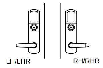
- Rotate lever to proper orientation for door, install square drive spindle into back of trim.
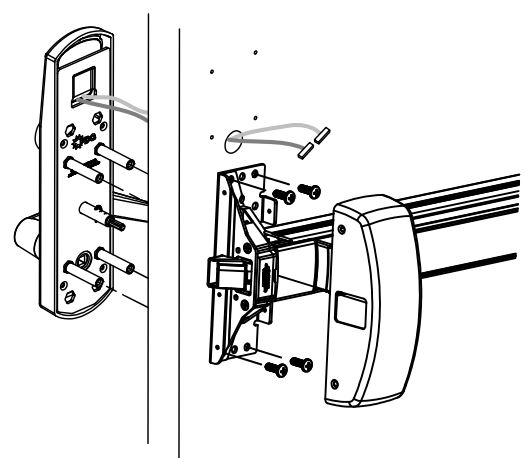
2. INSTALL TRIM AND EXIT DEVICE
- Prepare door according to included template.
- Install escutcheon trim onto door while feeding wires through door.
- Install exit device and secure with (4) included pan head screws.
- Rim Device: Install chassis/head cover.
- SVR Device: Skip to step 4
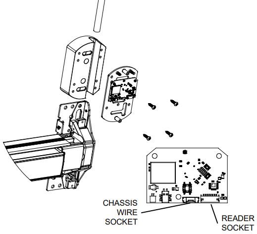
3. RIM DEVICE – INSTALL CONTROL BOARD
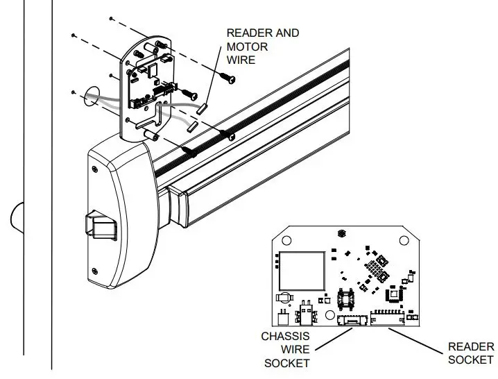
- Install control board assembly feed wires through slot under circuit board.
- Secure assembly with (4) included wood/ metal screws.
- Make wire connection after control board is installed. Push extra wire into door cavity.
4. SVR DEVICE – INSTALL SPACER & CONTROL BOARD
- Install rod spacer block with (2) included wood/metal screws feed wires through slot in block.
- Install top rod before control board.
- Install control board assembly feed wires through slot under circuit board and secure assembly with (4) wood/metal screws.
- Make wire connections after control board installed. Push extra wire into door cavity.
- Install Chassis/Head cover
5. INSTALL BATTERY PACK
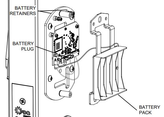
- Plug battery wire into control board.
- Install battery pack over two studs on mounting plate and snap battery pack onto retainers on control board assembly.
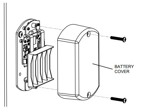
6. INSTALL BATTERIES AND BATTERY COVER
- Install batteries and battery cover with (2) pan head screws.