![]()
Instructions for use
Contents
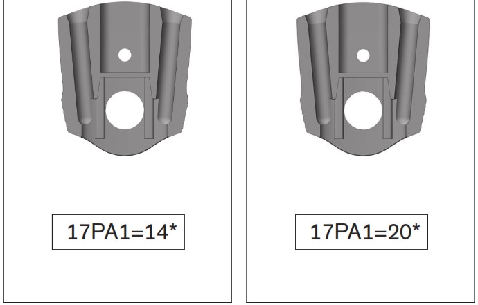
17PA1=14 Foot Stirrup for Plastic Ankle Joint
INFORMATION
Date of last update: 2022-08-16
► Please read this document carefully before using the product and observe the safety notices.
► Instruct the user in the safe use of the product.
► Please contact the manufacturer if you have questions about the product or in case of problems.
►Report each serious incident related to the product to the manufacturer and to the relevant authority in your country. This is particularly import ant when there is a decline in the health state.
► Please keep this document for your records.
These instructions for use provide you with important information on the pro cessing of the 17PA1=*WR waterproof orthotic ankle joints made of plastic.
Product description
2.1 Available sizes
| Reference number | Size | Insertion zone in mm | Material |
| 17PA1*–WR | *=14 | 14 | Plastic |
| 17PA1*–WR | *=20 | 20 |
2.2 Components/design
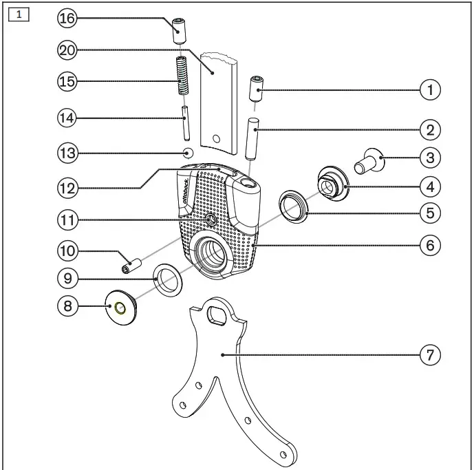
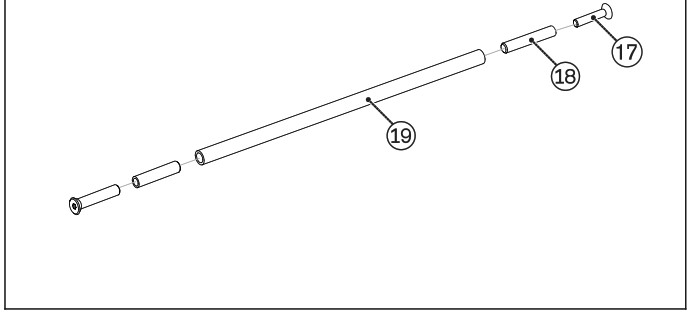
| Scope of delivery (see fig. 1) | ||||||
| Item | Quantity [Piece(s)] | Designa- tion | Article number | |||
| 17PA1=14 | 17PA1=20 | |||||
| 1 | 2 | Set screw | 506G21=M6x14 | |||
| 2 | 2 | Cylinder pin | 506A5=5x- M6x6 | 506A27=5- xM6x20 |
||
| 3 | 1 | Joint screw | 29PA1=14 | 29PA1 | ||
| 4 | 1 | Joint bolt | ||||
| 5 | 1 | Bushing | ||||
| 6 | 1 | Ankle joint | ||||
| 8 | 1 | Joint nut | 29PA1=14 | 29PA1 | ||
| 9 | 1 | Bushing | ||||
| 10 | 1 | Set screw | 506G21=M4x12 | |||
| 11 | 1 | Bore hole for set screw |
||||
| 12 | 1 | Insertion zone for bar | ||||
| 13 | 2 | Ball | 509Y1=5.0 | |||
| 14 | 2 | Cylinder pin | 506A8=2x-16 | 506A8=2.- 5×18 |
||
| 15 | 2 | Compres- sion spring | 513087=- 0.75×2.95-x2 |
513018=- 4.7×31-2 |
||
| 16 | 2 | Set screw | 30Y289 | 506G21=- M6x14 | ||
| 17 | 2 | Screw | 501S84=-M4x25 | 501T28=- M6x35 | ||
| 18 | 2 | Adapter for parallel alignment tube | 29PK4=14 | |||
| 19 | 1 | Parallel alignment tube | 30Y216 | |||
| Not included in the scope of delivery (see fig.1) | ||||
| Item | Quantity [Piece (s)] | Designation | Reference number | |
| 7 | 1 | Foot stirrup | 17PF1* | |
| 20 | 1 | Bar | 651P4*, 605P8* | |
Intended use
3.1 Indications for use
The waterproof orthotic joints made of plastic are to be used exclusively in pairs for lower limb orthotic fittings in waterproof walking devices. The waterproof walking aid is intended for use in wet areas, e.g. transfer into a pool, and is not a replacement for the initial orthosis.
| Article number | Max. body weight |
| 17PA1=14-WR | 45 kg |
| 17PA1=20-WR | 100 kg |
3.2 Indications
- Partial or total paralysis of the leg muscles
- Orthopaedic diseases of the lower limbs Indications must be determined by the physician.
3.3 Further Usage Restrictions
The product is not suitable for use in sports.
3.4 Lifetime
The product is designed for a lifetime of 3 years when used as intended and assembled professionally.
3.5 Qualification
Patients may be fitted with the product only by trained qualified personnel. The qualified personnel must be familiar with the handling of the various techniques, materials, machines and tools.
3.6 Combination possibilities
The 17PA1* orthotic ankle joints can be combined with the 17PK1* orthotic knee joints.
Safety
4.1 Explanation of warning symbols
![]()
Warning regarding possible risks of accident or injury.
![]()
Warning regarding possible technical damage.
4.2 Safety instructions
![]()
Excessive strain on load-bearing components
Injuries due to changes in or loss of functionality
► Only use the product for the defined area of application.
► If the product has been exposed to extreme strain (e.g. due to falling), take any necessary measures (e.g. repair, replacement, inspection by the manufacturer’s customer service, etc.).
![]()
Incorrect alignment or assembly Injuries due to changes in or loss of functionality
► The product may only be installed by trained, qualified personnel.
► Observe the alignment and assembly instructions.
![]()
Mechanical damage to the product
Injuries due to changes in or loss of functionality
► Use caution when working with the product.
► Check the product for proper function and readiness for use.
► In case of changes in or loss of functionality, discontinue use of the product and have it checked by authorized, qualified personnel.
![]()
Excessive strain due to use on more than one patient
Risk of injury and loss of functionality as well as damage to the product
► Use the product on only one patient.
► Observe the maintenance recommendations.
![]()
Unallowable use of lubricants
Risk of injury and loss of functionality as well as damage to the product
► The product is designed to be free of lubricants. Avoid contact with lubricants (e.g. grease, oil).
► After contact with lubricants, promptly clean the product or parts of the product with a degreasing cleaning agent (e.g. acetone or isopropyl alcohol).
![]()
Contact with saltwater or water containing chlorine/soap, fresh water or abrasive substances (e.g. sand)
Damage and premature product wear
► Following any contact with the substances identified above, promptly clean the product in accordance with the section “Cleaning”.
![]()
Exposure of the product to unsuitable environmental conditions
Damage, brittleness or destruction due to improper handling
► Avoid storage in condensing ambient humidity.
► Avoid contact with abrasive substances (e.g. sand, dust).
► Do not expose the product to temperatures below -10 °C (14 °F) or above +60 °C (140 °F) (e.g. sauna, excessive sunlight, drying on a radiator).
Preparing the product for use
INFORMATION
► Check that the orthotic joints are aligned in the parallel position before delivering the orthosis.
INFORMATION
An adjustment aid is included with each pair of orthotic joints so the orthot ic joints can be aligned parallel to one another. The adjustment aid con sists of two screws, one parallel alignment tube and, depending on the size of the orthotic joints, two adapter pieces.
Mounting the foot stirrup
- Slide the bearing bushings onto the orthotic joint.
- Secure the foot stirrup with the joint bolt and joint nut.
- Screw the joint nut together with the joint screw.
- Clean the threads of the screw connections using a degreasing cleaner and secure them with Loctite 241.
Mounting the compression spring
> Prerequisite: The foot stirrup is mounted.
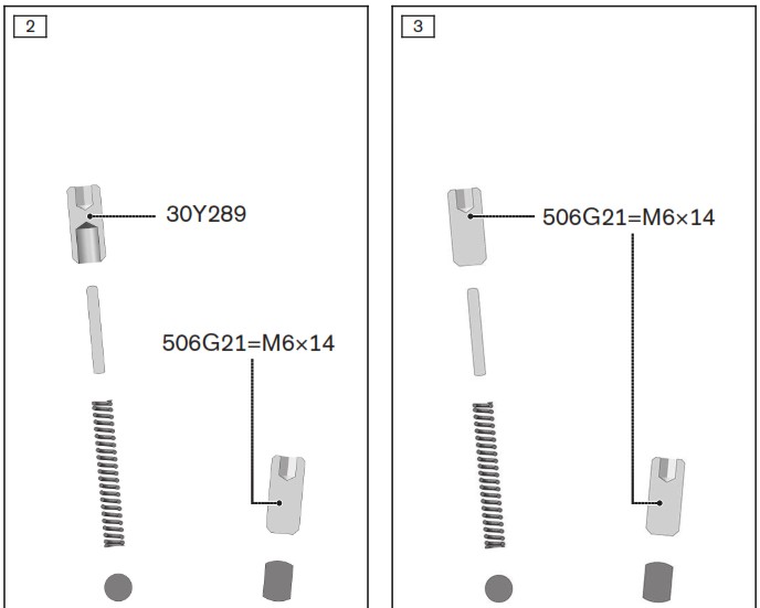
- Insert the ball, compression spring and cylinder pin into the threaded hole (see fig. 2, see fig. 3).
- Screw the set screw into the threaded hole and set the spring force of the ankle joint.
- Clean the threads of the screw connections using a degreasing cleaner and secure them with Loctite 241.
Mounting the stop pin
> Prerequisite: The foot stirrup is mounted.
- Insert the stop pin into the threaded hole (see fig. 2, see fig. 3).
- Screw the set screw into the threaded hole and set the angle of the orthotic joint.
- Clean the threads of the screw connections using a degreasing cleaner and secure them with Loctite 241.
Mounting the bar
> Required tools: 624S14=4 drill bit, 726S9=90×11.5 counterbore.
- Insert the bar into the insertion zone of the orthotic joint and mark the position of the bore hole.
- Use the 624S14* drill bit to make the bore hole.
- Deburr the bore with the 726S9* counterbore.
- Secure the bar in the insertion zone with the 506G21* set screw.
INFORMATION: The bars are glued in the insertion zone to com plete the assembly.
Gluing in bars
Required materials: 636W28* special adhesive, degreasing cleaner The bars must be glued in the insertion zones to ensure stability.
- Clean the connecting surfaces with a degreasing cleaner.
- Apply the special adhesive to the connecting surfaces.
- Insert the bars.
- Secure with the enclosed screws.
- Allow to cure for at least 4 hours.
INFORMATION: Final bonding strength will be reached after 16 hours.
Removing the bar
- Unscrew the set screw.
- Tap out and remove the bar.
17PA1*
The 17PA1* orthotic ankle joints are adapted to the needs of the patient through the individual combination of the ball, stop pin and compression spring with the set screws. The following combinations are possible:
| Combination | Intended use | ||
| Installation position Anterior | Installation position Posterior | ||
| Stop pin | Stop pin | e.g. ICP or spina bifida | |
| Compression spring | Stop pin | Support for dorsal extension, e.g. in case of lower leg muscle weakness, to prevent hyper- extension of the knee joi nt or for energy return during toe-off | |
| Compression spring | Compression spring | Dorsal and plantar support, e.g. in case of lower leg muscle weakness | |
| Stop pin | Compression spring | Dorsiflexion assist with adjustable dorsal stop, e.g. in case of peroneal paralysis with or without own muscular knee joint protection | |
Cleaning
Promptly clean the product after contact with:
- Water containing salt, chlorine or soap, perspiration, urine or splashed water (e.g. after rain) and soiling.
1) Rinse the product with clear fresh water.
2) Dry the product with a cloth or allow it to air dry. Avoid exposure to direct heat (e.g. from an oven or radiator).
Clean the product immediately after contact with:
- Lubricants (e.g. oil and grease)
1) Wet a cloth with a degreasing cleaner.
2) Wipe the orthotic joints or components with the cloth.
Maintenance
INFORMATION
The product may be exposed to increased loads by the patient.
► Shorten the maintenance intervals according to the expected loads.
The manufacturer requires at least a semi-annual inspection of the product to verify functionality and check for wear.
Spare parts are listed in the section “Components/design”.
Replacing the bushing
- Loosen the joint screw and remove the joint bolt and joint nut from the orthotic joint.
- Disassemble the orthotic joint.
- Insert the new bushing into the orthotic joint.
- Assemble the orthotic joint with the joint bolt, joint nut and joint screw.
- Clean the threads of the screw connections using a degreasing cleaner and secure them with Loctite 241.
Disposal
Dispose of the product in accordance with national regulations.
Legal information
All legal conditions are subject to the respective national laws of the country of use and may vary accordingly.
9.1 Liability
The manufacturer will only assume liability if the product is used in accord acne with the descriptions and instructions provided in this document. The manufacturer will not assume liability for damage caused by disregarding the information in this document, particularly due to improper use or unauthorized modification of the product.
9.2 CE conformity
The product meets the requirements of Regulation (EU) 2017/745 on medic al devices. The CE declaration of conformity can be downloaded from the manufacturer’s website.
![]()
_______________________________
The 17PA1 CarbonIQ Joints are covered by the following registered designs and design patents:
| Columbia: | 6521 |
| China: | ZL 201030667653.8 |
| European Design: | 1725771 |
| India: | 232772 |
| Mexico: | 34538 |
| Russia: | 81299 |
| Taiwan: | R.O.C. Design Patent D 143075 |
| Turkey: | IR-Design DM/074831 in TR |
| USA: | Design Patent US D658,771 S |
Design patent pending in: Brazil.
![]()
Ottobock SE & Co. KGaA
Max-Näder-Straße 15 · 37115 Duderstadt · Germany
T +49 5527 848-0 · F +49 5527 848-3360
[email protected] · www.ottobock.com
© Ottobock · 647G799=all_INT-11-2208