Contents
NHD-0216HZ Newhaven Display

Product Specification
- Model: NHD-0216HZ-FL-YBW-C
- Manufacturer: Newhaven Display International, Inc.
- Address: 2661 Galvin Court, Elgin, IL 60124 USA
- Phone: 847.844.8795
- Fax: 847.844.8796
- Website: www.newhavendisplay.com
- Compliance: REACH Compliant, RoHS Compliant
Product Description
- Type: 2×16 Character LCD
- Driver IC: ST7066U
- Driving Mode: 1/16 Duty, 1/5 Bias
- Interface: 4/8-bit 6800 Parallel
- Power Requirement: 5.0V LCD, 4.2V/85mA Backlight
- Optical Features: STN (+) Yellow/Green, Transflective, 6:00 View, Yellow/Green Backlight
- Recommended Pin Header: 1×16 pin 2.54mm pitch
Additional Resources
- Support Forum: https://support.newhavendisplay.com/hc/en-us/community/topics
- GitHub: https://github.com/newhavendisplay
- Example Code: https://support.newhavendisplay.com/hc/en-us/categories/4409527834135-Example-Code/
- Knowledge Center: https://www.newhavendisplay.com/knowledge_center.html
- Quality Center: https://www.newhavendisplay.com/quality_center.html
- Precautions for using LCDs/LCMs: https://www.newhavendisplay.com/specs/precautions.pdf
- Warranty / Terms & Conditions: https://www.newhavendisplay.com/terms.html
Document Revision History
| Revision | Date | Description | Changed By |
|
0 |
10/23/2008 |
Initial Release |
– |
|
1 |
11/13/2009 |
User Guide Reformat |
BE |
|
2 |
12/08/2009 |
Backlight Info Updated |
BE |
|
3 |
01/06/2010 |
Optical Updated |
BE |
|
4 |
06/25/2010 |
Mechanical Drawing, Pin Description, Block Diagram Updated |
MP |
|
5 |
07/15/2010 |
Side View of Pins Added to Mechanical Drawing |
MC |
|
6 |
10/29/2010 |
Mechanical Drawing Updated |
BE |
|
7 |
01/06/2011 |
Alternate Controller Information Updated |
AK |
|
8 |
03/08/2011 |
Pins Removed from Drawing |
BE |
|
9 |
04/19/2011 |
Electrical Characteristics Updated |
AK |
|
10 |
11/01/2011 |
Mechanical Drawing Updated |
BE |
|
11 |
11/26/2013 |
Mechanical Drawing updated, Timing Characteristics added, User Guide Reformat |
ML |
|
12 |
11/04/2016 |
Mechanical Drawing, Electrical & Optical Char. Updated |
SB |
|
13 |
02/20/2019 |
Mechanical & Backlight Characteristics Updated |
SB |
|
14 |
08/05/2020 |
Clarified Pin 3 as Do Not Connect |
AS |
|
15 |
12/14/2021 |
Mechanical Drawing Updated |
CJ |
|
16 |
04/15/2024 |
Backlight Voltage Updated |
KL |
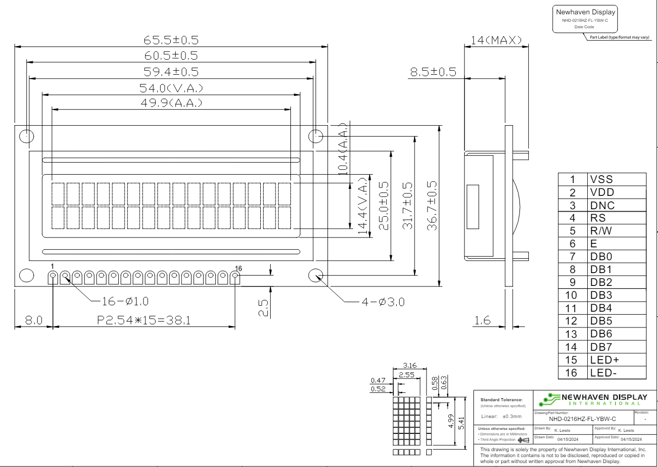
Mechanical Drawing
Product Description: 2×16 Character LCD
- Driver IC: ST7066U
- Driving Mode: 1/16 Duty, 1/5 Bias
- Interface: 4/8-bit 6800 Parallel
- Power Requirement: 5.0V LCD, 4.2V/85mA Backlight
- Optical Features: STN (+) Yellow/Green, Transflec?ve, 6:00 View, Yellow/Green Backlight
- Recommended Pin Header: 1×16 pin 2.54mm pitch
Pin Description
| Pin No. | Symbol | External Connection | Function Description |
| 1 | VSS | Power Supply | Ground |
| 2 | VDD | Power Supply | Supply Voltage for Logic (+5.0V) |
| 3 | DNC | DNC | Do No Connect (Contrast Voltage is internally controlled) |
| 4 | RS | MPU | Register Select signal. RS=0: Command, RS=1: Data |
| 5 | R/W | MPU | Read/Write select signal, R/W=1: Read R/W: =0: Write |
| 6 | E | MPU | Operation Enable signal. Falling edge triggered. |
| 7-10 | DB0 – DB3 | MPU | Four low order bi-directional three-state data bus lines. These four are not used during 4-bit operation. |
| 11-14 | DB4 – DB7 | MPU | Four high order bi-directional three-state data bus lines. |
| 15 | LED-A | Power Supply | Backlight Anode (4.2V) |
| 16 | LED-K | Power Supply | Backlight Cathode (Ground) |
Recommended LCD connector: 2.54mm pitch pins
- Backlight connector: —
- Mates with: —
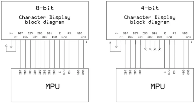
Wiring Diagram
Characteristics
Electrical Characteristics
| Item | Symbol | Condition | Min. | Typ. | Max. | Unit |
| Operating Temperature Range | TOP | Absolute Max | -20 | – | +70 | ⁰C |
| Storage Temperature Range | TST | Absolute Max | -30 | – | +80 | ⁰C |
| Supply Voltage | VDD | – | 4.7 | 5.0 | 5.3 | V |
| Supply Current | IDD | VDD = 5.0V TOP = 25°C | 0.5 | 1.5 | 2.5 | mA |
| Supply for LCD (contrast) | VLCD | 4.2 | 4.4 | 4.6 | V | |
| “H” Level input | VIH | – | 0.7*VDD | – | VDD | V |
| “L” Level input | VIL | – | VSS | – | 0.6 | V |
| “H” Level output | VOH | – | 3.9 | – | VDD | V |
| “L” Level output | VOL | – | VSS | – | 0.4 | V |
| Backlight Supply Voltage | VLED | – | 4.0 | 4.2 | 4.4 | V |
| Backlight Supply Current | ILED | VLED = 4.2 | 40 | 85 | 120 | mA |
Optical Characteristics
| Item | Symbol | Condition | Min. | Typ. | Max. | Unit | ||
| Optimal Viewing Angles | Top | ϕY+ |
CR ≥ 2 |
– | 40 | – | ⁰ | |
| Bottom | ϕY- | – | 60 | – | ⁰ | |||
| Left | θX- | – | 60 | – | ⁰ | |||
| Right | θX+ | – | 60 | – | ⁰ | |||
| Contrast Ratio | CR | – | 2 | 5 | – | – | ||
| Response Time | Rise | TR | TOP = 25°C | – | 150 | 250 | ms | |
| Fall | TF | – | 200 | 300 | ms | |||
Controller Information
Built-in ST7066U Controller: https://support.newhavendisplay.com/hc/en-us/articles/4414848155159-ST7066U
DDRAM Address
| 1 | 2 | 3 | 4 | 5 | 6 | 7 | 8 | 9 | 10 | 11 | 12 | 13 | 14 | 15 | 16 |
| 00 | 01 | 02 | 03 | 04 | 05 | 06 | 07 | 08 | 09 | 0A | 0B | 0C | 0D | 0E | 0F |
| 40 | 41 | 42 | 43 | 44 | 45 | 46 | 47 | 48 | 49 | 4A | 4B | 4C | 4D | 4E | 4F |
Table of Commands
|
Instruction |
Instruction code |
Description |
Execution
time (fOSC= 270 KHZ |
|||||||||
| RS | R/W | DB7 | DB6 | DB5 | DB4 | DB3 | DB2 | DB1 | DB0 | |||
| Clear Display |
0 |
0 |
0 |
0 |
0 |
0 |
0 |
0 |
0 |
1 |
Write “20H” to DDRAM and set DDRAM address to “00H” from AC |
1.52ms |
|
Return Home |
0 |
0 |
0 |
0 |
0 |
0 |
0 |
0 |
1 |
– |
Set DDRAM Address to “00H” from AC and return cursor to its original position if shifted. The contents of DDRAM are not changed. |
1.52ms |
|
Entry mode Set |
0 |
0 |
0 |
0 |
0 |
0 |
0 |
1 |
I/D |
SH |
Sets cursor move direction and specifies display shift. These parameters are performed
during data write and read. |
37µs |
| Display ON/ OFF control |
0 |
0 |
0 |
0 |
0 |
0 |
1 |
D |
C |
B |
D=1: Entire display on C=1: Cursor on
B=1: Blinking cursor on |
37µs |
|
Cursor or Display shift |
0 |
0 |
0 |
0 |
0 |
1 |
S/C |
R/L |
– |
– |
Sets cursor moving and display shift control bit, and the direction without changing DDRAM data. |
37µs |
|
Function set |
0 |
0 |
0 |
0 |
1 |
DL |
N |
F |
– |
– |
DL: Interface data is 8/4 bits N: Number of lines is 2/1
F: Font size is 5×11/5×8 |
37µs |
| Set CGRAM
Address |
0 | 0 | 0 | 1 | AC5 | AC4 | AC3 | AC2 | AC1 | AC0 | Set CGRAM address in address counter | 37µs |
| Set DDRAM
Address |
0 | 0 | 1 | AC6 | AC5 | AC4 | AC3 | AC2 | AC1 | AC0 | Set DDRAM address in address counter. | 37µs |
|
Read busy Flag and Address |
0 |
1 |
BF |
AC6 |
AC5 |
AC4 |
AC3 |
AC2 |
AC1 |
AC0 |
Whether during internal operation or not can be known by reading BF. The contents of address counter can also be
read. |
0s |
| Write data To Address | 1 | 0 | D7 | D6 | D5 | D4 | D3 | D2 | D1 | D0 | Write data into internal RAM (DDRAM/CGRAM). | 37µs |
| Read data From RAM | 1 | 1 | D7 | D6 | D5 | D4 | D3 | D2 | D1 | D0 | Read data from internal RAM (DDRAM/CGRAM). | 37µs |
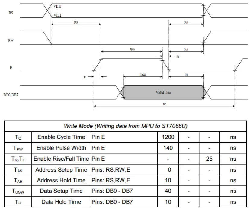
Timing Characteristics
Writing data from MPU to ST7066U
Reading data from ST7066U to MPU

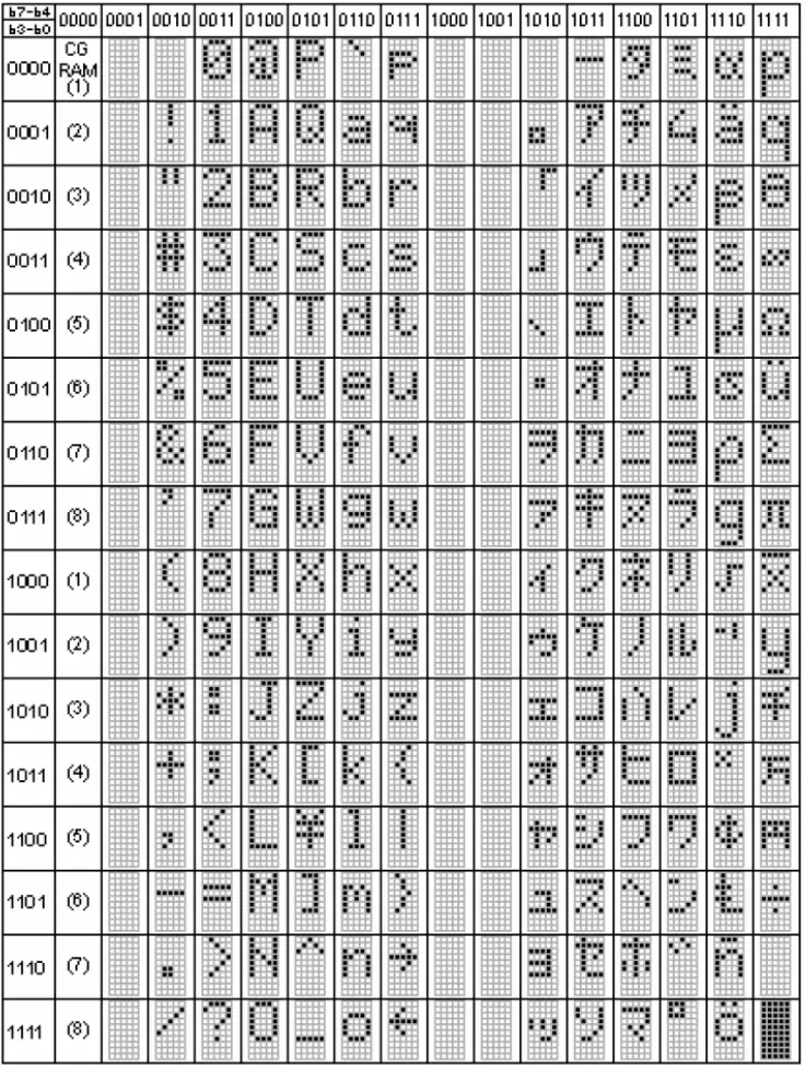
Built-in Font Table
Example Initialization Program
8-bit Initialization: //void command(char i)
- P1 = i; //put data on output Port
- D_I =0; //D/I=LOW : send instruction
- R_W =0; //R/W=LOW : Write
- E = 1;
- Delay(1); //enable pulse width >= 300ns
- E = 0; //Clock enable: falling edge
void write(char i)
- P1 = i; //put data on output Port
- D_I =1; //D/I=HIGH : send data
- R_W =0; //R/W=LOW : Write
- E = 1;
- Delay(1); //enable pulse width >= 300ns
- E = 0; //Clock enable: falling edge
void init()
- E = 0;
- Delay(100); //Wait >40 msec after power is applied
- command(0x30); //command 0x30 = Wake up
- Delay(30); //must wait 5ms, busy flag not available
- command(0x30); //command 0x30 = Wake up #2
- Delay(10); //must wait 160us, busy flag not available
- command(0x30); //command 0x30 = Wake up #3
- Delay(10); //must wait 160us, busy flag not available
- command(0x38); //Function set: 8-bit/2-line
- command(0x10); //Set cursor
- command(0x0c); //Display ON; Cursor ON
- command(0x06); //Entry mode set
4-bit Initialization:
void command(char i)
- P1 = i; //put data on output Port
- D_I =0; //D/I=LOW : send instruction
- R_W =0; //R/W=LOW : Write
- Nybble(); //Send lower 4 bits
- i = i<<4; //Shift over by 4 bits
- P1 = i; //put data on output Port
- Nybble(); //Send upper 4 bits
void write(char i)
- P1 = i; //put data on output Port
- D_I =1; //D/I=HIGH : send data
- R_W =0; //R/W=LOW : Write
- Nybble(); //Clock lower 4 bits
- i = i<<4; //Shift over by 4 bits
- P1 = i; //put data on output Port
- Nybble(); //Clock upper 4 bits
void Nybble()
- E = 1;
- Delay(1); //enable pulse width >= 300ns
- E = 0; //Clock enable: falling edge
void init()
- P1 = 0;
- P3 = 0;
- Delay(100); //Wait >40 msec after power is applied
- P1 = 0x30; //put 0x30 on the output port
- Delay(30); //must wait 5ms, busy flag not available
- Nybble(); //command 0x30 = Wake up
- Delay(10); //must wait 160us, busy flag not available
- Nybble(); //command 0x30 = Wake up #2
- Delay(10); //must wait 160us, busy flag not available
- Nybble(); //command 0x30 = Wake up #3
- Delay(10); //can check the busy flag now instead of the delay
- P1= 0x20; //put 0x20 on the output port
- Nybble(); //Function set: 4-bit interface
- command(0x28); //Function set: 4-bit/2-line
- command(0x10); //Set cursor
- command(0x0F); //Display ON; Blinking cursor
- command(0x06); //Entry Mode set
Quality Information
| Test Item | Content of Test | Test Condition | Note |
| High Temperature storage | Endurance test applying the high storage
temperature for a long time. |
+80⁰C , 48hrs | 2 |
| Low Temperature storage | Endurance test applying the low storage temperature for a long time. | -30⁰C , 48hrs | 1,2 |
| High Temperature Operation | Endurance test applying the electric stress (voltage & current) and the high thermal
stress for a long time. |
+70⁰C 48hrs | 2 |
| Low Temperature Operation | Endurance test applying the electric stress (voltage & current) and the low thermal stress for a long time. | -20⁰C , 48hrs | 1,2 |
| High Temperature / Humidity Operation | Endurance test applying the electric stress (voltage & current) and the high thermal
with high humidity stress for a long time. |
+40⁰C , 90% RH , 48hrs | 1,2 |
| Thermal Shock resistance | Endurance test applying the electric stress (voltage & current) during a cycle of low
and high thermal stress. |
0⁰C,30min -> 25⁰C,5min ->
50⁰C,30min = 1 cycle 10 cycles |
|
| Vibration test | Endurance test applying vibration to simulate transportation and use. | 10-55Hz , 15mm amplitude. 60 sec in each of 3 directions X,Y,Z
For 15 minutes |
3 |
| Static electricity test | Endurance test applying electric static discharge. | VS=800V, RS=1.5kΩ, CS=100pF
One time |
- Note 1: No condensation to be observed.
- Note 2: Conducted after 4 hours of storage at 25⁰C, 0%RH.
- Note 3: Test performed on the product itself, not inside a container.
FAQ
- Q: What is the recommended power supply voltage for the backlight?
- A: The recommended power supply voltage for the backlight is 4.2V.