
NameLessRC D400 VTX+DVR AIO
User Manual

Contents
Specification:
-Brand Name: NameLessRC
-Item Name: D400 VTX+DVR AIO
-Input Power: 5V
-Output Power: PIT/25mW/100mW/200mW/400mW Switchable
-Frequency: 5.8GHz 6 bands 48 channels, with Raceband: 5362-5945 MHZ
-Control Mode: BFOSD Control/ Button, IRC Tramp ready
-Video Output format: NTSC
-Record video size : 1280×720 @30FPS
-TF Card support: Max.32G
-Compress Format: AVI
-Microphone: Yes
-Antenna: IPEX
-Mounting hole: 26.5*26.5mm
-Weight: 3.5g without antenna
Features:
-VTX maximum power up to 400mW.
-Built-in microphone.
-Support to choose recording FC OSD info or not.
-Start/Stop recording via button or OSD. Automatic recording after power on.
-Automatically save a video every 5 minutes.
-Cable plug and welding pads are both available.
-Small & light size for whoop and toothpick style frames.
-The VTX will not be damaged even if the antenna is dropped.
Attention:
-VTX’s default setup is on lock mode(5733-5866MHZ unlock). Please follow your local laws and regulations if you need to unlock the frequency.
-Please format the TF card to FAT/FAT32.
Pins Assignment:

 Note:
Note:
You can choose to use the included cables or welding pads according to your needs.
Precautions for use:
-Please maintain a good cooling environment for better performance.
-Input voltage must be within the specified range 5V.
-Please choose antenna with good VSWR and DB if you replace, to get far transmission distance.
-Please use good TF card for better recording quality.
-Pay attention to static electricity protection during transportation and installation.
Control methods: VTX lock/unlock
(D400 VTXcable for Betaflight 4.1: https://drive.google.com/open?id=1LR2UCBB_0OrupfQlvufxuH7ozPHD-1YI)
-The VTX is set up via BFOSD Control (IRC Tramp) or button.
-The VTX’s default set up is lock on 25mw.
-To lock/unlock the VTX :
Option 1: Long press the VTX button for 25 seconds after power on. The 3 LEDs will flash one by one if the VTX is successful to unlock. Please re-power the VTX after this step.
Option 2: Please enter the PIT mode for three times within 30secs after powering up the VTX (PIT mode switch is set in BF mode page). The 3 LEDs will flash one by one if the VTX is successful to unlock. Please re-power the VTX after this step.
VTX LED functions:
-Orange LED shows channels status. Green for bands and Blue for power. -The Green LED flash after Orange and blue LED flash at the same time means the VTX enters PIT mode successfully.
-The three LEDs will flash one by one after the VTX is powered. After that, each LED will flash to show the channel, band & power’s status. Orange LED flash 1 time for Channel 1, 2 times for Channel 2. Green LED flash 1 time for Band 1, 2 times for Band 2, and so on. The three LEDs will flash one by one again after finish showing the status.
VTX Channel/Band/Power set up:
-Power the D400 and long press VTX button for 3 seconds. The Channel Orange LED will flash. 1 time for Channel 1, 2 times for Channel 2 and so on. Short press to switch the Channel.
-Long press VTX button for 3 seconds after step 1, the Band Green LED will flash.
1 time for Band 1, 2 times for Band 2 and so on. Short press to switch the Band.-Long press VTX button for 3 seconds after step 2, the Power Blue LED will flash.
1 time for 25mW, 2 times for 100mW and so on. Short press to switch the Power.
-Long press VTX button for 3 seconds after step 3 or re-power the D400, the set up will be saved.(Re-power during each step also can save the set up)
Frequency Table(Mhz):
Red area on frequency table is locked area! Please follow your local laws and regulations.
|
Channel |
1 |
2 |
3 |
4 |
5 |
6 |
7 |
8 |
|
Band A |
5865 |
5845 |
5825 |
5805 |
5785 |
5765 |
5745 |
5725 |
|
Band B |
5733 |
5752 |
5771 |
5790 |
5809 |
5828 |
5847 |
5866 |
|
Band E |
5705 |
5685 |
5665 |
5645 |
5885 |
5905 |
5925 |
5945 |
|
FS |
5740 |
5760 |
5780 |
5800 |
5820 |
5840 |
5860 |
5880 |
|
Race Band |
5658 |
5695 |
5732 |
5769 |
5806 |
5843 |
5880 |
5917 |
|
Low Race |
5362 |
5399 |
5436 |
5473 |
5510 |
5547 |
5584 |
5621 |
DVR Recording:
–DVR White LED constantly bright means it is in standby, flashing means recording.
Option 1: Automatic recording after power on.
Option 2: Short press the DVR button to start/stop recording.
Option 3: Start/stop recording via OSD control (Video: https://youtu.be/v9MAinKmdsQ)
-Enter the OSD VTX set up page

-Switch the POWER to ON and confirm. The code will show 513 which means the DVR is starting to recording. Meanwhile, the DVR White LED will be flashing.
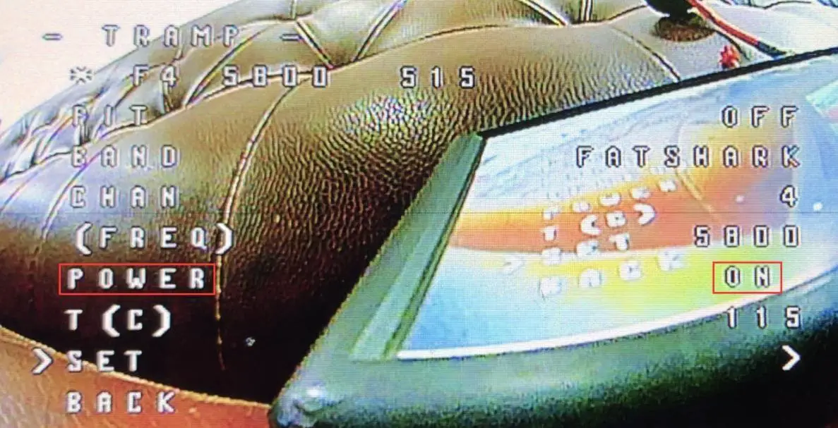
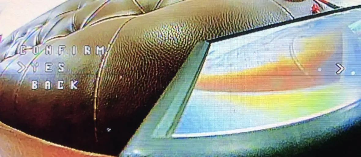

-Switch the POWER to OFF and confirm. The code will show 515 which means the DVR stop recording. Meanwhile, the DVR White LED will be constantly bright.


Note: We recommend setting the power you expect again after start/stop recording via OSD.
NameLessRC D400 VTX DVR AIO User Manual – Download [optimized]
NameLessRC D400 VTX DVR AIO User Manual – Download