Contents
mXion MWB Retrofit Kit For LGB Switch Housing
Product Information
The MWB is a device that requires careful installation and operation. It is important to read the user manual and warning notes thoroughly before using the device. The device is not a toy and is recommended for users aged 15 and above.
There are several important notes to consider:
- Ensure that the outputs are set to appropriate values before connecting any other device to avoid damage.
- The switch address is determined by CV120/121. For addresses below 256, only write to CV121.
- Set CV124 correctly to your switch to prevent damage to the gears. Adjust CV124 again when setting speed and power using CV122.
Table of Contents
The user manual includes the following sections:
- General information
- Summary of functions
- Scope of supply
- Hook-Up
- Connectors MWB
- Contact inputs
- Heart piece, siding
- Product description
- Automatic switch back
- Inversion
- Decouple-Mode
- Programming lock
- Programming options
- Programming binary values
- Programming switch address
- Reset functions
- Analogue operation
- Function output features
- CV-Table
- Technical data
- Warranty, Service, Support
- EC declaration of conformity
- WEEE Directive
- Hotline
It is important to note that some functions may only be available with the latest firmware. Make sure to update your device if necessary.
Product Usage Instructions
Hook-Up
- Install the device according to the connecting diagrams provided in the manual.
- Ensure that the device is protected against shorts and excessive loads.
- Check for connection errors such as shorts or improper mounting screws that can cause a short circuit.
- Close the two holes for track connection to prevent water from entering the device.
- Set CV124 correctly to your switch to avoid damaging the gears. Adjust CV122 for speed and power as needed, and readjust CV124 accordingly.
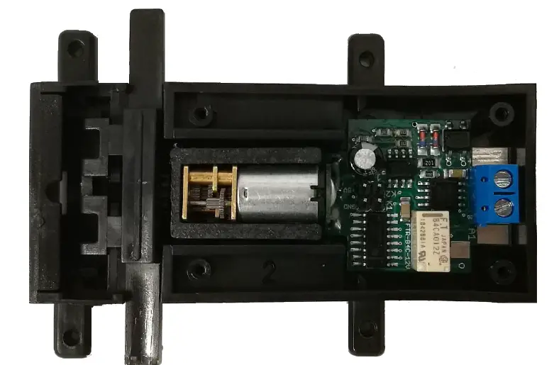
Connectors MWB
To switch loads, connect between A1 and DEC+. The engine gears are strong and can work in both analog and digital modes. To activate or deactivate K1, close contact K1/GND once during the start. After that, K1 can be used to switch the drive digitally or analogously.
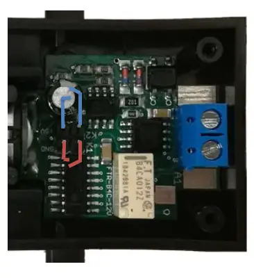
Contact inputs
In addition to the function output, the MWB has 2 contact inputs.
Introduction
Dear customer, we strongly recommend that you read these manuals and the warning notes thouroughly before installing and operating your device. The device is not a toy (15+).
NOTE: Make sure that the outputs are set to appropriate value before hooking up any other device. We can’t be responsible For any damage if this is disregarded.
NOTE: The switch address is by CV120/121! For addresses < 256 you need only write to CV121!
NOTE: SET CV124 correct to your switch, else you damage the gears. With CV122 you can set speed and power and need to adjust also CV124 again!
General information
We recommend studying this manual thoroughly before installing and operating your new device.
NOTE: Some functions are only available with the latest firmware. Please make sure that your device is programmed with the latest firmware.
NOTE: SET CV124 correct to your switch, else you damage the gears. With CV122 you can set speed and power and need to adjust also CV124 again!
Summary of Functions
- DC/AC/DCC operation
- Compatible NMRA-DCC module
- Also usable analog (EPL-Table)
- Injection ABS plastic
- Weatherproof
- LGB latern and switches usable!
- Switch input for manuel control (2x)
- Real slow switching
- Speed configurable (CV122)
- High-Quality gear engine with metal gears Also usable for LGB® signals
- 1 reinforced function output (latern, e.g.) Heart polarisation included (relais, too) Defined start switching position
- Outputs invertable
- Decoupler mode
- Automatic switch back functions
- Function output dimmable
- Reset function for all CV values
- Easy function mapping
- adresses, 2048 switch adresses
- Multiple programming options
- (Bitwise, CV, POM accessoire decoder, register) Needs no programming load
Scope of supply
- Manual
- mXion MWB
Hook-Up
Install your device in compliance with the connecting diagrams in this manual. The device is protected against shorts and excessive loads. However, in case of a connection error e.g. a short this safety feature can’t work and the device will be destroyed subsequently.
Make sure that there is no short circuit caused by the mounting screws or metal.
NOTE: Please note the CV basic settings in the delivery state.
NOTE: Please note that you close the two holes for track connection to avoid that water can get into the device.
NOTE: SET CV124 correct to your switch, else you damage the gears.
With CV122 you can set speed and power and need to adjust also CV124 again!
Connectors MWB
Switch loads between A1 and DEC+.
The gears of the engine are very strong! The engine will work analog and digital!
To (de)activate K1, once during the start of start of contact K1/GND be closed. Thereafter, K1 can be used to digitally & analogously to switch the drive (e.g. signals).

Contact inputs
In addition to the function output MWB has via 2 contact inputs.
If CV49 bit 7 = 0 is the first contact input (marked red) active and switched to GND. This always switched the switch in the other direction (standard delivery).
If CV49 bit 7 = 1 (value 128), the 2. contact input active (function output deactivated, marked blue). Now you can define with the one contact input the switch to „right“ or „left“ direction. This switched against +5V.
Use reed, switch, trigger buttons.
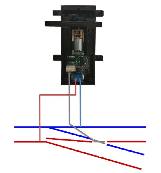
Heart piece, siding
The relay can be used to centerpieces polarize (see picture below) to switch sidings with the switch direction.
Product description
The mXion MWB is a engine derived switch with 1 function output for switch lanterns or signal lighting also heart polarization with included relay.
Therefore, the centerpiece simply inside the MWB are connected. In case of short circuit must the connection wires of the MWB are reversed once become.
Highlight of the MWB is the setting for decoupling tracks. Here you can create a corresponding function output CV 49 Bit 0/1 and automatically with of the switch. The advantage is that the luminous “E” of the LGB® decoupling track as the decouple is active. Now, weather the decouple is still disengaged or coupling.
Ideally, the mode, complement each other with the mode for defined position of SW1. The output of the switched switch automatically to „stop“ or „branch“.
This hast he advantage that signals on red, decoupling tracks to normal and turn switches to „branch“ after the system has been switched on.
So you always have a defined starting position (invertible).
Automatic switch back
Over CV123 it is possible to activate an automatic switch back function. After time switch goes to last position.
Also it is possible to activate over CV49 Bit 1 and 2 a defined starting position where the switch drives through after power on cycle.
Inversion
Over CV49 Bit 3 and 4 the switch and A1 direction can be inverted.
Decouple-Mode
Over CV49 Bit0 it is possible to activate the Ent coupler mode. A1 switches now on if the track uncouples.
Programming lock
To prevent accidental programming to prevent CV 15/16 one programming lock. Only if CV 15 = CV 16 is a programming possible. Changing CV 16 changes automatically also CV 15.
With CV 7 = 16 can the programming lock reset. STANDARD VALUE CV 15/16 = 185
Programming options
This decoder supports the following programming types: bitwise, POM and CV read & write and register-mode.
There will be no extra load for programming.
In POM (programming on main track) the programming lock is also supported. The decoder can also be on the main track programmed without the other decoder to be influenced. Thus, when programming the decoder can not be removed.
NOTE: To use POM without others decoder must affect your digital center POM to specific decoder addresses.
Programming binary values
Some CV’s (e.g. 29) consist of so-called binary values. The means that several settings in a value. Each function has a bit position and a value. For programming such a CV must have all the significances can be added. A disabled function has always the value 0.
EXAMPLE: You want 28 drive steps and long loco address. To do this, you must set the value in CV 29 2 + 32 = 34 programmed.
Programming switch address
Switch addresses consist of 2 values.
For addresses < 256 the value can be directly in address low. The high address is 0. If the address is > 255 this is as follows (for example address 2000):
- 2000 / 256 = 7,81, address high is 7
- 2000 – (7 x 256) = 208, address low is then 208.
Program these values into the SW1 CVs CV120/121 and A2 (CV127/128).
Reset functions
The decoder can be reset via CV 7. Various areas can be used for this purpose. Write with the following values:
- 11 (basic functions)
- 16 (programming lock CV 15/16)
- 33 (function and switch outputs)
Analogue operation
The MWB works digitally as well as analog. In analog mode, the frog polarization works as well as digital. In analog mode, the drive be operated in 2 ways.
- Via the classic EPL control panel with the push buttons and alternating current. Relay will not work.
- With any permanent voltage to the terminals and a switch. Only in this mode does this work core relay and the function output properly. If the drive to be switched (direction change) just need a contact bet. K1/GND produced (e.g. REED, switch, etc..).
To (de)activate the 2nd mode during the switching on of the drive K1/GND bridged become. Then the mode is saved. At press K1/GND again during startup the mode is deactivated again.
Function output features
| Function | A1 | SW1 | Time value |
| On/Off | X | X | |
| Deactivated | X | ||
| Permanent-On | X | ||
| Forwards only | |||
| Backwards only | |||
| Standing only | |||
| Driving only | |||
| Timer sym. flash | X | ||
| Timer asym. short | X | ||
| Timer asym. long | X | ||
| Monoflop | X | ||
| Switch on delay | X | ||
| Firebox | |||
| TV flickering | |||
| Photographer flash | X | ||
| Petroleum flickering | |||
| Flourescent tube | |||
| Pairwise alternating | X | ||
| Autom. switch back | X | X | |
| Dimmable | X | X |
CV-Table
CV-Table S = Default, A = analog use, if √
| CV | Description | S | A | Range | Note | ||
| 7 | Software version | – | – | read only (10 = 1.1) | |||
| 7 | Decoder reset functions | ||||||
| 3 ranges available | 11 16 33 |
basic settings (CV 1,11-13,17-19,29-119) programming lock (CV 15/16) function- & Switch outputs (CV 120-139) | |||||
| 8 | Manufacturer ID | 160 | – | read only | |||
| 7+8 | Register programming mode | ||||||
| Reg8 = CV-Address Reg7 = CV-Value | CV 7/8 don’t changes his real value CV 8 write first with cv-number, then CV 7 write with value or read (e.g.: CV 49 should have 3) è CV 8 = 49, CV 7 = 3 writing |
||||||
| 15 | Programming lock (key) | 185 | 0 – 255 | to lock only change this value | |||
| 16 | Programming lock (lock) | 185 | 0 – 255 | changes in CV 16 will change CV 15 | |||
| 29 | NMRA configuration | 132 | √ | 128/132 | 128 = only digital, 132 = digital/analoge | ||
| 48 | Switch address calculation | 0 | 0/1 | 0 = Switch adress like norm
1 = Switch adress like Roco, Fleischmann |
|||
| 49 | mXion configuration | 0 | √ | bitwise programming | |||
| Bit | Value | OFF (Value 0) | ON | ||||
| 0 | 1 | A1 normal function | A1 for decouplertrack lamp | ||||
| 1 | 2 | SW1 no defined position | SW1 defined position | ||||
| 2 | 4 | SW1 def. position „straight“ | SW1 def. position „turned“ | ||||
| 3 | 8 | SW1 normal output | SW1 inverted output | ||||
| 4 | 16 | A1 normal output | A1 inverted output | ||||
| 5 | 32 | Heart polarization normal | Heart polarization invert | ||||
| 6 | 64 | A1 normal function | A1 flashes while turning | ||||
| 7 | 128 | A1 normal function | A1 as 2nd input | ||||
| 100 | Contact deactive | 0 | √ | 0/1 | 0 = active, 1 = deactive contact inputs | ||
| 115 | Contact lock time | 0 | √ | 0 – 255 | time base 0,25 sec. / value | ||
| 120 | Switch address 1 (SW1) high | 0 | 1 – 2048 | switch engine, if address smaller 256 easy programm CV121 = desired address! | |||
| 121 | Switch address 1 (SW1) low | 1 | |||||
| 122 | SW1 high dimming value/speed | 30 | √ | 1 – 35 | dimming value in % (1 % approx. 0,2 V) | ||
| 123 | SW1 time for automatic switch back function | 0 | √ | 0 – 255 | 0 = off 1 – 255 = time base 0,25 sec. each value |
||
| 124 | SW1 switch off time
(depends from CV122) |
4 | √ | 0 – 255 | 0 = permanent on 1 – 255 = time base 0,25 sec. each value |
||
| 126 | A1 dimming value | 100 | √ | 1 – 100 | dimming value in % (1 % ca. 0,2 V) | ||
| 127 | A1 address high | 0 | 1 – 2048 | switch output 1, if address smaller 256 easy programm CV121 = desired address! | |||
| 128 | A1 address low | 2 | |||||
| 129 | A1 time for special function | 10 | √ | 1 – 255 | time base (0,1s / value) | ||
Technical data
- Power supply: 7-27V DC/DCC 5-18V AC
- Current: 5mA (with out functions)
- Maximum function current:
- A1 0.1 Amps.
- SW1 0.25 Amps.
- Heart relay 3 Amps.
- Temperature range: -40 up to 85°C
- Dimensions L*B*H (cm): 8.8*4.2*1.9
NOTE: In case you intend to utilize this device below freezing temperatures, make sure it was stored in a heated environment before operation to prevent the generation of condensed water. During operation is sufficient to prevent condensed water.
Warranty, Service, Support
Micron-dynamics warrants this product against defects in materials and workmanship for one year from the original date of purchase. Other countries might have different legal warranty situations. Normal wear and tear, consumer modifications as well as improper use or installation are not covered. Peripheral component damage is not covered by this warranty. Valid warrants claims will be serviced without charge within the warranty period. For warranty service please return the product to the manufacturer. Return shipping charges are not covered by micron-dynamics. Please include your proof of purchase with the returned good. Please check our website for up to date brochures, product information, documentation and software updates. Software updates you can do with our updater or you can send us the product, we update for you free.
Errors and changes excepted.
EC declaration of conformity
This product meets the requirements of the following EC directives and bears the CE mark for this.
2014/30/EU on electromagnetic compatibility. Underlying standards: EN 55014-1 and EN 61000-6-3. To the electromagnetic compatibility during operation to maintain, follow the instructions in this guide.
EN IEC 63000:2018 to limit the use of certain hazardous substances in electrical and electronic equipment (RoHS).
WEEE Directive
This product meets the requirements of EU Directive 2012/19/EC on electrical and waste electronic equipment (WEEE). Dispose of this product does not have the (unsorted) household waste, but run it the recycling to. WEEE: DE69511269
Hotline
For technical support and schematics for application examples contact:
- micron-dynamics
- [email protected]
- [email protected]
www.micron-dynamics.de
https://www.youtube.com/@micron-dynamics