
Contents
MITSUBISHI ELECTRIC PLFY-WL06NEMU-E Split Type Heat Pump Air Conditioners
Product Information
Specifications
- Product Type: Split-Type Heat Pump Air Conditioners
- Model Names (Indoor Unit): PLFY-WL06NEMU-E, PLFY-WL08NEMU-E, PLFY-WL12NEMU-E, PLFY-WL15NEMU-E, PLFY-WL18NEMU-E, PLFY-WL24NEMU-E, PLFY-WL30NEMU-E, PLFY-WL36NEMU-E, PLFY-WL48NEMU-E
- Model Name (Grille): PLP-41EAEU
- Service Reference: PLFY-WL06NEMU-E.TH, PLFY-WL08NEMU-E.TH, PLFY-WL12NEMU-E.TH, PLFY-WL15NEMU-E.TH, PLFY-WL18NEMU-E.TH, PLFY-WL24NEMU-E.TH, PLFY-WL30NEMU-E.TH, PLFY-WL36NEMU-E.TH, PLFY-WL48NEMU-E.TH
- Revised Edition: REVISED EDITION-A
Parts Names and Functions
The user manual provides detailed information on the safety precautions, parts names, and functions of the split-type heat pump air conditioners. It includes diagrams and explanations of the various parts and their roles in the system.
4-Way Airflow System
The 4-way airflow system is a unique feature of the split-type heat pump air conditioners. It allows for efficient and even distribution of air in all directions, ensuring optimal cooling or heating performance.
Outlines and Dimensions
The outlines and dimensions section provides accurate measurements and diagrams of the indoor and outdoor units, as well as the grille model. This information is useful for installation purposes and determining the appropriate placement of the
units.
Wiring Diagram
The wiring diagram illustrates the electrical connections required for the split-type heat pump air conditioners. It provides a clear visual representation of how to connect the various components, ensuring proper installation and operation.
Refrigerant System Diagram
The refrigerant system diagram shows the flow of refrigerant within the split-type heat pump air conditioners. It helps users understand the refrigerant cycle and identify potential issues or leaks that may occur.
Microprocessor Control
The microprocessor control section explains the advanced control features of the split-type heat pump air conditioners. It provides instructions on how to use the control panel or remote controller to set temperature, mode, fan speed, and other settings.
Troubleshooting
The troubleshooting section offers a comprehensive list of common issues that may arise during the operation of the split-type heat pump air conditioners. It provides step-by-step instructions on how to identify and resolve these problems.
Disassembly Procedure
The disassembly procedure section provides guidance on how to disassemble the split-type heat pump air conditioners for maintenance or repair purposes. It includes detailed instructions, diagrams, and precautions to ensure safe disassembly and reassembly.
Remote Controller
The remote controller section explains the functions and operation of the remote controller provided with the split-type heat pump air conditioners. It provides instructions on how to use the remote controller to adjust settings, set timers, and activate special features.
Product Usage Instructions
Safety Precautions
Prior to installation and performing electrical work, it is crucial to read and follow the safety precautions provided in the user manual. These precautions ensure personal safety and prevent damage to the unit. Some important safety precautions include:
- Consulting the local power authority before connecting the unit to the power supply system
- Avoiding actions that must be avoided, such as coming into contact with rotating parts or wet electrical parts
- Using only the specified type of refrigerant during installation or relocation
- Taking caution when moving or reinstalling the unit to avoid water leakage, electric shock, or fire
- Checking for refrigerant leaks after completing service work
- Not attempting to defeat the safety features of the unit
Frequently Asked Questions (FAQ)
Q: Can I use a different type of refrigerant than what is indicated on the unit?
A: No, using any other type of refrigerant may adversely affect the refrigerant cycle and cause damage to the unit. It is recommended to only use the specified type of refrigerant.
Q: What should I do if I encounter an issue with the split-type heat pump air conditioners?
A: Refer to the troubleshooting section in the user manual for step-by-step instructions on identifying and resolving common issues. If the problem persists, contact your dealer or a qualified technician for assistance.
Q: Can I disassemble the unit myself for maintenance?
A: The user manual provides a disassembly procedure section with instructions on how to disassemble the unit for maintenance purposes. However, it is recommended to exercise caution and follow the instructions carefully. If you are unsure, it is advisable to seek the help of a professional technician.
SPLIT-TYPE, HEAT PUMP AIR CONDITIONERS
August 2023
No. TCH124
REVISED EDITION-A
TECHNICAL & SERVICE MANUAL
Indoor unit [Model names] PLFY-WL06NEMU-E
PLFY-WL08NEMU-E
PLFY-WL12NEMU-E
PLFY-WL15NEMU-E
PLFY-WL18NEMU-E
PLFY-WL24NEMU-E
PLFY-WL30NEMU-E
PLFY-WL36NEMU-E
PLFY-WL48NEMU-E
Grille model [Model name] PLP-41EAEU
Revision: · Some descriptions have been
revised in REVISED EDITION-A.
TCH124 is void.
Model name indication for MAIN UNIT
INDOOR UNIT
Model name indication for GRILLE
SAFETY PRECAUTION
Read before installation and performing electrical work
Thoroughly read the following safety precautions prior to installation. Observe these safety precautions for your safety. This equipment may have adverse effects on the equipment on the same power supply system. Contact the local power authority before connecting to the system.
Symbol explanations
WARNING
This symbol indicates that failure to follow the instructions exactly as stated poses the risk of serious injury or death.
CAUTION
This symbol indicates that failure to follow the instructions exactly as stated poses the risk of serious injury or damage to the unit.
Indicates an action that must be avoided.
Indicates important instructions.
Indicates a parts that requires grounding. Indicates that caution must be taken with rotating parts. (This symbol is on the main unit label.) <Color: Yellow> Indicates that the parts that are marked with this symbol pose a risk of electric shock. (This symbol is on the main unit label.) <Color: Yellow>
Keep electrical parts away from water.
– Wet electrical parts pose a risk of electric shock, smoke, or fire. Securely attach the control box cover. – If the cover is not installed properly, dust or water may infiltrate and pose a
risk of electric shock, smoke, or fire. Only use the type of refrigerant that is indicated on the unit when installing or relocating the unit. – Infiltration of any other types of refrigerant or air into the unit may adversely
affect the refrigerant cycle and may cause the pipes to burst or explode. Consult your dealer or a qualified technician when moving or reinstalling the unit. – Improper installation may result in water leakage, electric shock, or fire. After completing the service work, check for a refrigerant leak. – If leaked refrigerant is exposed to a heat source, such as a fan heater, stove,
or electric grill, toxic gases will be generated. Do not try to defeat the safety features of the unit. – Forced operation of the pressure switch or the temperature switch by defeat-
ing the safety features for these devices, or the use of accessories other than the ones that are recommended by Mitsubishi Electric may result in smoke, fire, or explosion. Consult your dealer for proper disposal method. Do not use a leak detection additive.
Precautions for handling units for use with water
WARNING
Carefully read the labels affixed to the main unit.
WARNING
Do not use refrigerant other than the type indicated in the manuals provided with the unit and on the nameplate. – Doing so may cause the unit or pipes to burst, or result in explosion or fire during use, during repair, or at the time of disposal of the unit. It may also be in violation of applicable laws. MITSUBISHI ELECTRIC CORPORATION cannot be held responsible for malfunctions or accidents resulting from the use of the wrong type of refrigerant. Ask your dealer or a qualified technician to install the unit. – Improper installation by the user may result in water leakage, electric shock, or fire. Properly install the unit on a surface that can withstand its weight. – Unit installed on an unstable surface may fall and cause injury. Only use specified cables. Securely connect each cable so that the terminals do not carry the weight of the cable. – Improperly connected cables may produce heat and start a fire. Take appropriate safety measures against wind gusts and earthquakes to prevent the unit from toppling over. – Improper installation may cause the unit to topple over and cause injury or damage to the unit. Only use accessories (i.e., air cleaners, humidifiers, electric heaters) recommended by Mitsubishi Electric. Do not make any modifications or alterations to the unit. Consult your dealer for repair. – Improper repair may result in water leakage, electric shock, or fire. Do not touch the heat exchanger fins with bare hands. – The fins are sharp and pose a risk of cuts. Properly install the unit according to the instructions in the Installation Manual. – Improper installation may result in water leakage, electric shock, or fire. Have all electrical work performed by an authorized electrician accord-ing to the local regulations and the instructions in this manual. Use a dedicated circuit. – Insufficient power supply capacity or improper installation of the unit may re-sult in malfunctions of the unit, electric shock, or fire.
CAUTION
Do not use the existing water piping. – Store the piping materials indoors, and keep both ends of the pipes sealed until immediately before installation. Keep the joints wrapped in plastic bags. If dust or dirt enters the water circuit, it may damage the heat exchanger and cause water leakage. Only use water. – Only use clean water as a refrigerant. The use of water outside the specification may damage the refrigerant circuit. Install the unit so that external force is not applied to the water pipes.
TCH124A
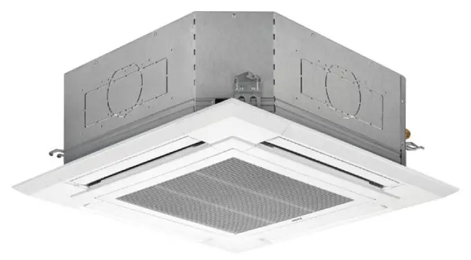
PARTS NAMES AND FUNCTIONS
2-1. Indoor unit
Air outlet Outlet pipe
Drain pipe
Filter
Inlet pipe
i-see Sensor (Option)
Model name indication for MAIN UNIT
Vane
Signal receiver (Option)
Model name indication for GRILLE
Air intake (Intake grille)
2-2. WIRED REMOTE CONTROLLER <PAR-41MAA> <PAC-YT53CRA>
The functions which can be used are restricted according to each model.
: Supported : Unsupported
Function
PAR-41MAA
Slim
CITY MULTI
PAC-YT53CRA
Body
Product size H × W × D
(mm)
120 × 120 × 14.5
120 × 70 × 14.5
(inch)
4-3/4 × 4-3/4 × 9/16
4-3/4 × 2-3/4 × 9/16
LCD
Full Dot LCD
Partial Dot LCD
Backlight
Energy saving Energy saving operation schedule
Automatic return to the preset temperature
Restriction
Setting the temperature range restriction
Function*
Operation lock function
Weekly timer
ON/OFF timer
High Power
Manual vane angle
*Some functions may not be available depending on model types. Refer to “11-1. REMOTE CONTROLLER FUNCTIONS” for details.
SPECIFICATIONS
SPECIFICATIONS
Model
PLFY-WL06NEMU-E.TH PLFY-WL08NEMU-E.TH PLFY-WL12NEMU-E.TH PLFY-WL15NEMU-E.TH PLFY-WL18NEMU-E.TH
Power source
1-phase 208/230 V 60Hz
Cooling capacity (Nominal)
*1 BTU/h *1 kW
6,000 1.8
8,000 2.3
12,000 3.5
15,000 4.4
18,000 5.3
Power input
kW
0.03
0.04
Current input
A
0.26
0.29
0.33
0.35
0.40
Heating capacity
*2 BTU/h
6,700
9,000
13,500
17,000
20,000
(Nominal)
*2 kW
2.0
2.6
4.0
5.0
5.9
Power input
kW
0.03
0.04
Current input
A
0.20
0.23
0.27
0.29
0.34
External finish
Galvanized steel plate
External dimension
inch
H × W × D
mm
10-3/16 × 33-2/32 × 33-2/32 258 × 840 × 840
Net weight
lbs (kg)
40 (18)
44 (20)
Decoration model
panel
External finish
PLP-41EAEU MUNSELL (1.0Y 9.2/0.2)
Dimension
inch
H × W × D
mm
1-9/16 × 37-13/32 × 37-13/32 40 × 950 × 950
Net weight
lbs (kg)
11 (5)
Heat exchanger
Cross fin (Aluminum fin and copper tube)
Water volume L
1.0
1.8
FAN
Type × Quantity
Turbo fan × 1
External static in.WG
0
press.
Pa
0
Motor type
DC motor
Motor output
kW
0.05
Driving mechanism
Direct-driven
Airflow rate
(Low-Mid2-Mid1-High)
cfm 424 – 459 – 494 – 530 424 – 459 – 530 – 600 494 – 530 – 565 – 600 494 – 530 – 565 – 600 494 – 565 – 636 – 706
K/min 12 – 13 – 14 – 15
12 – 13 – 15 – 17
14 – 15 – 16 – 17
14 – 15 – 16 – 17
14 – 16 – 18 – 20
L/s 200 – 217 – 233 – 250 200 – 217 – 250 – 283 233 – 250 – 267 – 283 233 – 250 – 267 – 283 233 – 267 – 300 – 333
Sound pressure level
(Low-Mid2-Mid1-High)
(measured in anechoic room) dB <A> 24 – 26 – 27 – 28 24 – 26 – 28 – 30 26 – 27 – 29 – 30 26 – 28 – 29 – 31 27 – 29 – 31 – 33
Insulation material
PS
Air filter
PP honeycomb (long life filter, anti-bacterial type)
Protection device
Fuse
Refrigerant control device
—
Connectable HBC controller
CMB-WP-NU-AA, CMB-WP-NU-AB
Water Connection Inlet mm O.D.
22
piping size
Outlet mm O.D.
22
diameter *3,*4
Field pipe size
Inlet mm I.D. Outlet mm I.D.
20 20
Field drain pipe size
inch (mm)
O.D. 1-1/4 (32)
Drawing External
VK01B213
Wiring
VM79A839
Refrigerant cycle
—
standard Document attachment Accessory
Installation Manual, Instruction Book Insulation template, Washer, Drain socket, Tie band
Optional 3D i-see Sensor corner panel
parts
Multi-function casement
PLP-41EAEU PAC-SJ41TM-E
High efficiency filter element
PAC-SH59KF-E
Air outlet shutter plate (1 set)
PAC-SJ37SP-E
Flange for fresh air intake
PAC-SH65OF-E
Wireless signal receiver
PAR-SR4LU-E
External heater adapter
PAC-YU25HT
Remark
* Details on foundation work, duct work, insulation work, electrical wiring, power source switch, and other items shall be referred to the Installation Manual.
* Due to continuing improvement, above specifications may be subject to change without notice.
Notes: 1. Norminal cooling conditions
Indoor: 80°FD.B./67°FW.B. (26.7°D.B./19.4°CW.B.), Outdoor: 95°FD.B. (35°CD.B.) Pipe length: 25 ft. (7.6 m), Level difference: 0 ft. (0 m) 2. Norminal heating conditions Indoor: 70°FD.B. (21.1°C.B.), Outdoor: 47°FD.B./43°FW.B. (8.3°CD.B./6.1°CW.B.) Pipe length: 25 ft. (7.6 m), Level difference: 0 ft. (0 m) 3. Be sure to install a valve on the water inlet/outlet. 4. Install a strainer (40 mesh or more) on the pipe next to the valve to remove the foreign matters.
Unit converter
Btu/h = kW × 3,412 cfm = m³/min × 35.31 lb = kg/0.4536 *Above specification data is subject to rounding variation.
TCH124A
4
Model
PLFY-WL24NEMU-E.TH
PLFY-WL30NEMU-E.TH
PLFY-WL36NEMU-E.TH
PLFY-WL48NEMU-E.TH
Power source
1-phase 208/230 V 60Hz
Cooling capacity
*1 BTU/h
24,000
30,000
36,000
48,000
(Nominal)
*1 kW
7.0
8.8
10.6
14.1
Power input
kW
0.04
0.05
0.08
0.11
Current input
A
0.40
0.46
0.66
1.05
Heating capacity
*2 BTU/h
27,000
34,000
40,000
54,000
(Nominal)
*2 kW
7.9
10.0
11.7
15.8
Power input
kW
0.04
0.05
0.08
0.11
Current input
A
0.34
0.40
0.60
0.99
External finish
Galvanized steel plate
External dimension
inch
H × W × D
mm
11-3/4 × 33-2/32 × 33-2/32 298 × 840 × 840
Net weight
lbs (kg)
53 (24)
57 (26)
Decoration model
panel
External finish
PLP-41EAEU MUNSELL (1.0Y 9.2/0.2)
Dimension
inch
H × W × D
mm
1-9/16 × 37-13/32 × 37-13/32 40 × 950 × 950
Net weight
lbs (kg)
11 (5)
Heat exchanger
Cross fin (Aluminum fin and copper tube)
Water volume L
2.1
2.2
3.1
FAN
Type × Quantity
Turbo fan × 1
External static in.WG
0
press.
Pa
0
Motor type
DC motor
Motor output
kW
0.12
Driving mechanism
Direct-driven
Airflow rate
(Low-Mid2-Mid1-High)
cfm
530 – 600 – 671 – 742
630 – 676 – 742 – 812
671 – 812 – 918 – 1059 706 – 883 – 1059 – 1236
K/min
15 – 17 – 19 – 21
15 – 18 – 21 – 23
19 – 23 – 26 – 30
20 – 25 – 30 – 35
L/s
250 – 283 – 317 – 350
250 – 300 – 350 – 383
317 – 383 – 433 – 500
333 – 417 – 500 – 583
Sound pressure level
(Low-Mid2-Mid1-High)
(measured in anechoic room) dB <A>
27 – 29 – 31 – 33
37 – 30 – 33 – 35
31 – 35 – 37 – 40
33 – 37 – 40 – 46
Insulation material
PS
Air filter
PP honeycomb (long life filter, anti-bacterial type)
Protection device
Fuse
Refrigerant control device
—
Connectable HBC controller
CMB-WP-NU-AA, CMB-WP-NU-AB
Water Connection Inlet mm O.D.
22
piping size
Outlet mm O.D.
22
diameter *3,*4
Field pipe size
Inlet mm I.D. Outlet mm I.D.
30 30
Field drain pipe size
inch (mm)
O.D. 1-1/4 (32)
Drawing External
VK01B213
Wiring
VM79A839
Refrigerant cycle
—
standard Document attachment Accessory
Installation Manual, Instruction Book Insulation template, Washer, Drain socket, Tie band
Optional 3D i-see Sensor corner panel
parts
Multi-function casement
PLP-41EAEU PAC-SJ41TM-E
High efficiency filter element
PAC-SH59KF-E
Air outlet shutter plate (1 set)
PAC-SJ37SP-E
Flange for fresh air intake
PAC-SH65OF-E
Wireless signal receiver
PAR-SR4LU-E
External heater adapter
PAC-YU25HT
Remark
* Details on foundation work, duct work, insulation work, electrical wiring, power source switch, and other items shall be referred to the Installation Manual.
* Due to continuing improvement, above specifications may be subject to change without notice.
Notes: 1. Norminal cooling conditions
Indoor: 80°FD.B./67°FW.B. (26.7°D.B./19.4°CW.B.), Outdoor: 95°FD.B. (35°CD.B.) Pipe length: 25 ft. (7.6 m), Level difference: 0 ft. (0 m) 2. Norminal heating conditions Indoor: 70°FD.B. (21.1°C.B.), Outdoor: 47°FD.B./43°FW.B. (8.3°CD.B./6.1°CW.B.) Pipe length: 25 ft. (7.6 m), Level difference: 0 ft. (0 m) 3. Be sure to install a valve on the water inlet/outlet. 4. Install a strainer (40 mesh or more) on the pipe next to the valve to remove the foreign matters.
Unit converter
Btu/h = kW × 3,412 cfm = m³/min × 35.31 lb = kg/0.4536 *Above specification data is subject to rounding variation.
TCH124A
5
3-2. ELECTRICAL PARTS SPECIFICATIONS
PLFY-WL06NEMU-E.TH PLFY-WL08NEMU-E.TH PLFY-WL24NEMU-E.TH PLFY-WL30NEMU-E.TH
Parts
Service name
Ref.
Symbol
PLFY-WL12NEMU-E.TH PLFY-WL18NEMU-E.TH
PLFY-WL15NEMU-E.TH
PLFY-WL36NEMU-E.TH PLFY-WL48NEMU-E.TH
Room temperature thermistor
TH21
Resistance 30°F/15.8 k”, 50°F/9.6 k”, 70°F/6.0 k”, 80°F/4.8 k”, 90°F/3.9 k”, 100°F/3.2 k”
Inlet pipe thermistor TH22
Resistance 30°F/15.8 k”, 50°F/9.6 k”, 70°F/6.0 k”, 80°F/4.8 k”, 90°F/3.9 k”, 100°F/3.2 k”
Outlet pipe thermistor TH23
Resistance 30°F/15.8 k”, 50°F/9.6 k”, 70°F/6.0 k”, 80°F/4.8 k”, 90°F/3.9 k”, 100°F/3.2 k”
Fuse (Indoor controller board)
FUSE
250 V 6.3 A
Fan motor
MF
8-pole OUTPUT 50 W
8-pole OUTPUT 120 W
Vane motor
MV
MSBPC20M13 DC12 V 300 “/phase
Drain pump
DP
PMD-12D13ME INPUT 3 W 24R/Hr
Drain float switch
FS
Open / Short detection
Power supply terminal block
TB2
(L1, L2) Rated to 330 V 30 A *
Transmission terminal block
TB5
(M1, M2, S) Rated to 250 V 20 A *
MA remote controller terminal block
TB15
(1, 2) Rated to 250 V 10 A *
*Refer to WIRING DIAGRAM for the supplied voltage.
3-3. SOUND PRESSURE LEVEL
PLFY-WL·NEMU-E
Measurement location Note: Measured in anechoic room.
1.5 m
Model name
Sound pressure level at anechoic room : Low-Mid2-Mid1-High Sound pressure level dB (A)
PLFY-WL06NEMU-E
24 – 26 – 27 – 28
PLFY-WL08NEMU-E
24 – 26 – 28 – 30
PLFY-WL12NEMU-E
26 – 27 – 29 – 30
PLFY-WL15NEMU-E
26 – 28 – 29 – 31
PLFY-WL18NEMU-E
27 – 29 – 31 – 33
PLFY-WL24NEMU-E
27 – 29 – 31 – 33
PLFY-WL30NEMU-E
27 – 30 – 33 – 35
PLFY-WL36NEMU-E
31 – 35 – 37 – 40
PLFY-WL48NEMU-E
33 – 37 – 40 – 46
TCH124A
6
3-4. NC CURVES
PLFY-WL06NEMU-E.TH FAN SPL(dB) LINE
High
28
Medium1 27
Medium2 26
Low
24
90
OCTAVE BAND SOUND PRESSURE LEVEL, dB0dB=0.0002bar)
80
70 NC-70
60 NC-60
50 NC-50
40 NC-40
30 NC-30
20
Approximate minimum audible limit on continuous noise
NC-20
10 63
125 250 500 1000 2000 4000 8000 BAND CENTER FREQUENCIES, Hz
OCTAVE BAND SOUND PRESSURE LEVEL, dB0dB=0.0002bar)
PLFY-WL08NEMU-E.TH FAN SPL(dB) LINE
High
30
Medium1 28
Medium2 26
Low
24
90
80
70 NC-70
60 NC-60
50 NC-50
40 NC-40
30 NC-30
20
10 63
Approximate minimum audible limit on continuous noise
125 250 500 1000 2000 4000 BAND CENTER FREQUENCIES, Hz
NC-20 8000
OCTAVE BAND SOUND PRESSURE LEVEL, dB0dB=0.0002bar)
PLFY-WL12NEMU-E.TH FAN SPL(dB) LINE
High
30
Medium1 29
Medium2 27
Low
26
90
80
70 NC-70
60 NC-60
50 NC-50
40 NC-40
30 NC-30
20
Approximate minimum audible limit on continuous noise
NC-20
10 63
125 250 500 1000 2000 4000 8000 BAND CENTER FREQUENCIES, Hz
TCH124A
7
OCTAVE BAND SOUND PRESSURE LEVEL, dB0dB=0.0002bar)
PLFY-WL15NEMU-E.TH FAN SPL(dB) LINE
High
31
Medium1 29
Medium2 28
Low
26
90
80
70 NC-70
60 NC-60
50 NC-50
40 NC-40
30 NC-30
20
Approximate minimum audible limit on continuous noise
NC-20
10 63
125 250 500 1000 2000 4000 8000 BAND CENTER FREQUENCIES, Hz
OCTAVE BAND SOUND PRESSURE LEVEL, dB0dB=0.0002bar)
PLFY-WL18NEMU-E.TH FAN SPL(dB) LINE
High
33
Medium1 31
Medium2 29
Low
27
90
80
70 NC-70
60 NC-60
50 NC-50
40 NC-40
30 NC-30
20
Approximate minimum audible limit on continuous noise
NC-20
10 63
125 250 500 1000 2000 4000 8000 BAND CENTER FREQUENCIES, Hz
OCTAVE BAND SOUND PRESSURE LEVEL, dB0dB=0.0002bar)
PLFY-WL24NEMU-E.TH FAN SPL(dB) LINE
High
33
Medium1 31
Medium2 29
Low
27
90
80
70 NC-70
60 NC-60
50 NC-50
40 NC-40
30 NC-30
20
Approximate minimum audible limit on continuous noise
NC-20
10 63
125 250 500 1000 2000 4000 8000 BAND CENTER FREQUENCIES, Hz
OCTAVE BAND SOUND PRESSURE LEVEL, dB0dB=0.0002bar)
PLFY-WL30NEMU-E.TH FAN SPL(dB) LINE
High
35
Medium1 33
Medium2 30
Low
27
90
80
70 NC-70
60 NC-60
50 NC-50
40 NC-40
30 NC-30
20
Approximate minimum audible limit on continuous noise
NC-20
10 63
125 250 500 1000 2000 4000 8000 BAND CENTER FREQUENCIES, Hz
TCH124A
OCTAVE BAND SOUND PRESSURE LEVEL, dB0dB=0.0002bar)
PLFY-WL36NEMU-E.TH
90
FAN SPL(dB)
High
40
Medium1 37
Medium2 35
Low
31
LINE
80
70 NC-70
60 NC-60
50 NC-50
40 NC-40
30 NC-30
20
Approximate minimum audible limit on continuous noise
NC-20
10 63
125 250 500 1000 2000 4000 8000 BAND CENTER FREQUENCIES, Hz
8
OCTAVE BAND SOUND PRESSURE LEVEL, dB0dB=0.0002bar)
PLFY-WL48NEMU-E.TH
90
FAN SPL(dB)
High
46
Medium1 40
Medium2 37
Low
33
LINE
80
70 NC-70
60 NC-60
50 NC-50
40 NC-40
30 NC-30
20
Approximate minimum audible limit on continuous noise
NC-20
10 63
125 250 500 1000 2000 4000 8000 BAND CENTER FREQUENCIES, Hz
TCH124A
9
4 4-WAY AIRFLOW SYSTEM
4-1. PLACEMENT OF THE AIR OUTLETS
· For this grille, the blowout direction comes in 11 patterns. Also, by setting switch on the controller board to the appropriate settings, you can adjust the airflow and speed. Select the settings from Table1 according to the location in which you want to install the unit.
1) Decide on the pattern of the airflow direction.
<Table 1>
4-direction
Pattern 1 Initial setting
3-direction
Pattern 4 1 air outlet fully closed
2-direction
Pattern 6 2 air outlet fully closed
Blowout direction pattern
Note1. For 3- and 2-direction settings, please use the air outlet shutter plate (option).
2) According to the number of air outlets and height of the ceiling to install the unit, be sure to set up the switch (SW21) on the circuit board to the appropriate setting. · Correspondence of ceiling heights to the number of air outlets
SW21
TCH124A
10
4-2. BRANCH DUCT HOLE AND FRESH AIR INTAKE HOLE
At the time of installation, use the duct holes (cut out) located at the positions shown in following diagram, as and when required. · A fresh air intake hole for the optional multi-functional casement can also be made.
Note: The figures marked with * in the drawing below represent the dimensions of the main unit excluding those of the optional multi-functional casement. When installing the optional multi-functional casement, add 5-5/16” (135 mm) to the dimensions marked on the figure. When installing the branch ducts, be sure to insulate adequately. Otherwise, condensation and dripping may occur.
A
A Branch duct hole
Fresh air intake hole
Unit : inch (mm)
Fresh air intake hole diagram
ø3-15/16 (ø100) cutout hole
ø4-29/32 (ø125) burring hole pitch
6-7/32 (158)
A
Inlet pipe Outlet pipe A
A Branch duct hole diagram
(view from either side)
15-11/32 (390)
3-17/32 3-15/16 3-15/16 3-17/32 (90) (100) (100) (90)
Drain pipe
Ceiling
6-9/16 (167) 6-3/32 (155)
3-15/16 (100)
5-1/8 (130)
13-25/32 × 3-15/16 (350×100) cutout hole
13-25/32 (350)
ø6-7/8 (ø175) burring hole pitch ø5-29/32 (ø150) cutout hole
4-3. OPERATION IN CONJUNCTION WITH DUCT FAN (Booster fan)
· Whenever the indoor unit is operating, the duct fan also operates. (1) Connect the optional multiple remote controller adapter (PAC-SA88HA-E) to the connector CN51 on the indoor controller board. (2) Drive the relay after connecting the 12 VDC relay between the Yellow and Orange connector lines. MB: Electromagnetic switch power relay for duct fan. X: Auxiliary relay (For 12 VDC, coil rating: 1.0 W or smaller)
CN51 on indoor
Be sure to secure insulation
~
material by tape, etc.
5 Green
Yellow –
controller
1
Orange +
MB
board Connector (5P) Red
Brown Indoor unit side
Multiple remote
Field installation
controller adapter
Be sure to secure insulation
PAC-SA88HA-E
material by tape, etc.
Indoor controller board
CN51
Distance between indoor controller board and relay must be within 33 ft [10 m]
Multiple remote controller adapter PAC-SA88HA-E
CN51
TCH124A
11
4-4. FRESH AIR INTAKE AMOUNT & STATIC PRESSURE CHARACTERISTICS PLFY-WL06/08/12/15/18/24/30/36/48NEMU-E
Static pressure [Pa(in.W.G.×10-2)]
Taking air into the unit
50(20)
Multi-functional casement + Standard filter
50(20)
Static pressure [Pa(in.W.G.×10-2)]
0 -50(-20) -100(-40)
0 -50(-20) -100(-40) -150(-60)
1 – inlet
2 – inlet
-150(-60)
-200(-80)
0
0.2
0.4
0.6
0.8
1
1.2
1.4 [CMM]
0
1
2
3
10
20
30
40
Airflow rate
[CFM]50
100
Airflow rate
Multi-functional casement + High efficiency filter
50(20)
How to read curves
4 150
5
6 [CMM]
200 [CFM]
0 -50(-20)
-100(-40) -150(-60)
-200(-80) 0
1 – inlet
2 – inlet
1
2
3
50
100
Airflow rate
4 150
5
6 [CMM]
200 [CFM]
Duct characteristics
1
Curve in the graphs
at site
0
BA C
Q
2
EC A
D
Q 3
Q Qa
A
Q…Designed amount of fresh air intake <CMM (CFM)>
A…Static pressure loss of fresh air intake duct system with airflow amount Q <Pa (in.W.G.o10-2)>
B…Forced static pressure at air conditioner inlet with airflow amount Q <Pa (in.W.G.o10-2)>
C…Static pressure of booster fan with airflow amount Q <Pa (in.W.G.o10-2)>
D…Static pressure loss increase amount of fresh air intake duct system for airflow amount Q <Pa (in.W.G.o10-2)>
E…Static pressure of indoor unit with airflow amount Q <Pa (in.W.G.o10-2)>
Qa…Estimated amount of fresh air intake without D <CMM (CFM)>
Static pressure [Pa(in.W.G.×10-2)]
TCH124A
12
5 OUTLINES AND DIMENSIONS
Unit: inch (mm)
TCH124A
13
6 WIRING DIAGRAM
TCH124A
14
7 REFRIGERANT SYSTEM DIAGRAM
Heat exchanger
Pipe temperature detection thermistor/ inlet TH22
Water inlet connection Water flow
Manual air purge valve
Pipe temperature detection thermistor/ outlet TH23
Water outlet connection Water flow
Room temperature detection thermistor TH21
WATER PIPE CONNECTION SIZE
Model name PLFY-WL06/08/12/15/18NEMU-E
Item
Water outlet
Min. I.D. 25/32 (20)
Water inlet
Min. I.D. 25/32 (20)
Unit: inch (mm)
PLFY-WL24/30/36/48NEMU-E Min. I.D. 1-3/16 (30) Min. I.D. 1-3/16 (30)
8 MICROPROCESSOR CONTROL
INDOOR UNIT CONTROL 8-1. COOL OPERATION
MENU
RETURN
SELECT HOLD
ON OFF
<How to operate> Press ON/OFF button. Press [F1] button to display COOL. Press [F2] [F3] button to set the set temperature. NOTE: The settable temperature range varies with the model of outdoor units and remote controller.
<How to operate> Press POWER ON/OFF button. Press the operation MODE button to display COOL. Press the TEMP. button to set the set temperature. NOTE: The set temperature changes 1°F when the or button is pressed one time. Cooling 67 to 87°F
.
TCH124A
15
Control Mode 1. Temperature
adjustment function
2. Fan
Control Details
Remarks
1-1. Determining temperature adjustment function (Function to prevent restarting for 3 minutes) · Room temperature Set temperature + 2°F ···Thermo-ON · Room temperature Set temperature ···Thermo-OFF
1-2. Anti-freeze control Condition to detect When the pipe temperature detection thermistor/liquid (TH22) detects 32°F or less in 16 minutes from thermo-ON, the anti-freeze control initiates, and the unit enters to the thermo-OFF.
Condition to release The timer which prevents reactivating is set for 3 minutes, and anti-freeze control is
· The ON/OFF commands by the indoor unit thermostatic control are not an ON/OFF commands to the compressor but an open/close commands to the linear expansion valve. (The compressor stops only when the thermostatic control for all the indoor units connected to the same outdoor unit turns OFF.)
Pipe temperature detection thermistor/liquid (TH22) reaches 50°F or above. The condition of thermo-OFF has been completed by the thermostat. The operation has changed to a mode other than COOLING.
By the remote controller setting (switch of 4 speeds+Auto)
Type 4 speeds + Auto type
Fan speed notch Auto
3. Drain pump
When [Auto] is set, fan speed is changed depending on the value of: T = Room temperature – Set temperature
High Med2 Med1 Low
1.8°F
3.15°F
5.4°F
T
3-1. Drain pump control · The drain pump will always run when the unit is in COOL or DRYING mode. (Regardless of the thermo ON/OFF) · Whenever the operation is changed over to the other modes (including Stop), the drain pump will stop pumping after approximately 3 minutes.
Float switch control · Float switch control judges whether the sensor is in the air or in the water by turning the
Float SW ON
OFF 15 s
15 s
15 s 1 min 30 s 1 min 30 s
4. Vane (up/down vane change)
In the water In the air
In the water
Error
Drain pump
postponement abnormal
(1) The initial vane setting for COOL mode will be the horizontal position. (2) Vane position:
Horizontal Downward A Downward B Downward CDownward DSwingAuto
· “1h” appears on the wired remote controller.
(3) Restriction of the downward vane setting If the vane position is set to Downward A/B/C/D in [Med1], [Med2], or [Low], the vane will return to the horizontal position after 1 hour has passed.
TCH124A
16
8-2. DRYING OPERATION
MENU
RETURN
SELECT HOLD
ON OFF
.
<How to operate> Press ON/OFF button. Press [F1] button to display DRYING. Press [F2] [F3] button to set the set temperature.
<How to operate> Press POWER ON/OFF button. Press the operation MODE button to display DRYING. Press the TEMP. button to set the set temperature. NOTE: The set temperature changes 1°F when the or button is pressed one time. Dry 67 to 87°F
Control Mode
1. Temperature adjustment function
Control Details
1-1. Determining temperature adjustment function (Function to prevent restarting for 3 minutes) Setting the Dry thermo by the thermostat signal and the room temperature (TH21). Dry thermo-ON Room temperature Set temperature + 2°F Dry thermo-OFF Room temperature Set temperature
3 minutes passed since
Dry thermo-
Room temperature
starting operation
ON time
Thermostat signal Room temperature (T1)
(min)
T1 83°F
9
Over 64°F
ON
83°F > T1 79°F
7
79°F > T1 75°F
5
75°F > T1
3
OFF
Unconditional
3
Below 64°F
Dry thermo OFF
Dry thermoOFF time (min)
3 3 3 3 10
2. Fan
1-2. Anti-freeze control No control function
Indoor fan operation controlled depends on the compressor conditions.
Dry thermo ON OFF
Fan speed notch [Low] Excluding the following Room temp. < 64°F
Note: Fan speed change is not allowed during DRYING operation.
Stop [Low]
3. Drain pump
4. Vane (up/down vane change)
Operates as it would in COOL operation. Settings are the same in DRYING operation as they are in COOL operation.
Remarks
TCH124A
FAN OPERATION
MENU
RETURN
SELECT HOLD
ON OFF
.
<How to operate> Press ON/OFF button. Press [F1] button to display FAN.
<How to operate> Press POWER ON/OFF button. Press the operation MODE button to display FAN.
Control Mode
1. Temperature adjustment function
Set by remote controller. Type
4 speeds + Auto type
Control Details Fan speed notch
Auto
Remarks
2. Drain pump
When [Auto] is set, fan speed becomes [Low]. 2-1. Drain pump control
ON for 3 minutes after the operation mode is switched from COOL or DRYING to another operation mode (FAN).
control judges the sensor is in the water.
2-2. Float switch control · Float switch control judges whether the sensor is in the air or in the water by turning the
· Operates as it would in COOL operation.
In the air
3. Vane (up/down vane change)
Same as the control performed during the COOL operation, but with no restriction on the vane’s downward blow setting
TCH124A
18
8-4. HEAT OPERATION
MENU
RETURN
SELECT HOLD
ON OFF
.
<How to operate> Press ON/OFF button. Press [F1] button to display HEAT. Press [F2] [F3] button to set the set temperature. NOTE: The settable temperature range varies with the model of outdoor units and remote controller.
<How to operate> Press POWER ON/OFF button. Press the operation MODE button to display HEAT. Press the TEMP. button to set the set temperature. NOTE: The set temperature changes 1°F when the or button is pressed one time. Heating 63 to 83°F
Control Mode
1. Temperature adjustment function
Control Details
1-1. Determining temperature adjustment function (Function to prevent restarting for 3 minutes) · Room temperature Set temperature -2°F ···Thermo-ON · Room temperature Set temperature ···Thermo-OFF
Remarks
2. Fan
By the remote controller setting (switch of 4 speeds+Auto)
Type 4 speeds + Auto type
Fan speed notch Auto
When [Auto] is set, fan speed is changed depending on the value of: T = Set temperature – Room temperature
Give priority to under-mentioned controlled mode 2-1. Hot adjust mode 2-2. Residual heat exclusion mode 2-3. 2-4. Cool air prevention mode (Defrosting mode)
stment function)
TCH124A
Continue to the next page.
19
Control Mode
Control Details
Remarks
2-1. Hot adjust mode The fan controller becomes the hot adjuster mode for the following conditions. When starting the HEAT operation
*1 “Heat Standby” will be displayed during the hot adjust mode.
When the temperature adjustment function changes from OFF to ON. When release the HEAT defrosting operation
*2 The step change of A to B will not be
Hot adjust mode*1
[Extra Low]*3 [Low]*3Set fan speed by the remote controller
thermo-ON mode since the HEAT operation has started.
[OFF]*2*3 The fan speed varies
A
B
C
D
according to the setting
A: Hot adjust mode starts. B: 5 minutes have passed since the condition A or the indoor liquid pipe temperature reached 86°F or more. C: 5 minutes have passed since the condition A or the indoor liquid pipe temperature reached 95°F or more.
of DIP SW1-7 and 1-8 as shown in the table below.
D: 2minutes have passed since the condition C. (Terminating the hot adjust mode)
ON DIP SW
1-7 OFF
DIP SW 1-8
ON
OFF
B to C [Extra Low] C to D [Low]
B to C [Low] C to D [Low]
B to C [Extra Low] C to D [Low]
Note: Initial setting
2-2. Residual heat exclusion mode When the condition changes the auxiliary heater ON to OFF (temperature adjustment function, or operation stop, etc.), the indoor fan operates in [Low] mode for 1 minute.
· This control is same for the model without auxiliary heater.
3. Drain pump
2-3. Thermo-OFF mode When the temperature adjustment function changes to OFF, the indoor fan operates in [Extra low].
2-4. Heat defrosting mode The indoor fan stops.
3-1. Drain pump control
ON for 3 minutes after the operation mode is switched from COOL or DRYING to another operation mode (FAN).
control judges the sensor is in the water.
3-2. Float switch control
· Operates as it would in
· Float switch control judges whether the sensor is in the air or in the water by turning the COOL operation.
4. Vane control (Up/down vane change)
(1) Initial setting: OFF HEAT···[last setting] When the last setting is [Swing] ··· [Downward D] When changing the mode from exception of HEAT to HEAT operation ···[Downward D] (2) Vane position: Horizontal Downward A Downward B Downward CDownward DSwingAuto
(3) Restriction of vane position
(The control by the remote controller is temporally invalidated and control by the unit.) · Thermo-OFF · Hot adjust [Extra low] mode · Heat defrost mode
TCH124A
20
8-5. AUTO OPERATION [AUTOMATIC COOL/HEAT CHANGE OVER OPERATION]
MENU
RETURN
SELECT HOLD
ON OFF
.
<How to operate> Press ON/OFF button. Press [F1] button to display AUTO. Press [F2] [F3] button to set the set temperature. NOTE: The settable temperature range varies with the model of outdoor units and remote controller.
<How to operate> Press POWER ON/OFF button. Press the operation MODE button to display AUTO. Press the TEMP. button to set the set temperature. NOTE: The set temperature changes 1°F when the or button is pressed one time. Automatic 67 to 83°F
Control Mode 1. Initial value of operation mode 2. Mode change
3. COOL mode 4. HEAT mode
Control Details
HEAT mode for room temperature < Set temperature COOL mode for room temperature Set temperature
(1) HEAT mode COOL mode Room temperature Set temperature + 3°F or 3 minutes have passed.
(2) COOL mode HEAT mode Room temperature Set temperature – 3°F or 3 minutes have passed.
Operates as it would in COOL operation.
Operates as it would in HEAT operation.
Remarks
8-6. WHEN UNIT IS STOPPED CONTROL MODE
Control Mode
Control Details
1. Drain pump
1-1. Drain pump control
Remarks
ON for 3 minutes after the operation mode is switched from COOL or DRYING to another operation mode (FAN).
control judges the sensor is in the water.
1-2. Float switch control · Float switch control judges whether the sensor is in the air or in the water by
· Operates as it would in COOL operation.
In the air
TCH124A
21
9 TROUBLESHOOTING
9-1. HOW TO CHECK THE PARTS
Parts name
Checkpoints
Room temperature detection thermistor (TH21) Pipe temperature detection thermistor/inlet (TH22) Pipe temperature detection thermistor/outlet (TH23)
Disconnect the connectors, then measure the resistance with a multimeter. (At ambient temperatures of 50°F ~ 86°F)
Normal 4.3 to 9.6 k
Abnormal Open or short
Refer to “9-1-1. Thermistor”.
Vane motor (MV)
White
Orange Red
Blue Yellow
Measure the resistance between the terminals with a multimeter. (At ambient temperatures of 68°F ~ 86°F)
Connector Red – Yellow
Normal
Red – Blue Red – Orange Red – White
300 ± 7%
Abnormal Open or short
Drain pump (DP)
1 Red 2 Purple 3 Black
Check if the drain float switch works properly. Check if the drain pump works and drains water properly in cooling operation. If no water drains, confirm that the check code 2502 will not be displayed 10 minutes after the operation starts. Note: The drain pump for this model is driven by the internal DC motor, so it is not possible to
measure the resistance between the terminals.
Normal
RedBlack: Input 13 VDC The fan starts to rotate. PurpleBlack: Abnormal (check code 2502) if it outputs 013 V square wave (5 pulses/rotation),
and the number of rotation is not normal.
Fan motor (MF)
Refer to “9-1-4. DC Fan motor (fan motor/indoor controller board)”.
Drain float switch (FS)
Measure the resistance between the terminals with a multimeter.
Moving part 1 2 3 4
State of moving part UP
DOWN
Normal Short Open
Abnormal Other than short Other than open
Switch Magnet
Moving part
TCH124A
22
Parts name i-see Sensor
1 2 34 1 2 34
Checkpoints
Turn the power ON while the i-see Sensor connector is connected to the CN4Z on indoor controller board. A communication between the indoor controller board and i-see Sensor board is made to detect the connection.
Normal: When the operation starts, the motor for i-see Sensor is driven to rotate the i-see Sensor. Abnormal: The motor for i-see Sensor is not driven when the operation starts.
Note: The voltage between the terminals cannot be measured accurately since it is pulse output.
Black Black Black Black 65432 1 32 1
i-see Sensor motor (MT) (Option)
White
Orange Red Blue Yellow
Pressure sensor (Optional parts)
Flow control valve
(FCV)
M FCV
(Optional parts)
CN8A Yellow 1 Orange 2 Red 3 Green 4 Blue 5 Purple 6 White 7 Gray 8
Measure the resistance between the terminals with a multimeter. (At ambient temperatures of 68°F ~ 86°F)
Connector Red – Yellow Red – Blue Red – Orange Red – White
Normal 250 ± 7%
Abnormal Open or short
Pressure sensor (inner water) PS1 Pressure sensor (outlet water) PS2 1. Check that the pressure sensor is connected. 2. Check the pressure sensor wiring for breakage.
Pressure 0-1.0 MPa [145 psi] Vout 0.5-4.5 V 0.392 V/ 0.098 MPa [14 psi] Pressure [MPa] = 0.25 × Vout [V] – 0.125 Pressure [psi] = (0.25 × Vout [V] – 0.125) × 145
PS1
GND(RED) Vout(Brown) Vcc(DC5V)(Orange)
PS2
Connector CNSA (White)
GND(Blue) Vout(White) Vcc(DC5V)(Yellow)
Connector CNSB (Black)
Disconnect the connector then measure the resistance between terminals with a multimeter. Refer to “9-1-2. Flow control valve”.
Normal
Abnormal
1-5
2-5
3-5
4-5
Purple-Brown Orange-Brown Blue-Brown Green-Brown Open or short
55 ± 5.6 (at 77°F
9-1-1. Thermistor <Thermistor characteristic graph>
Thermistors for lower temperature
Room temperature detection thermistor (TH21) Pipe temperature detection thermistor/inlet (TH22) Pipe temperature detection thermistor/outlet (TH23)
Thermistor R0=15 k” ± 3% Fixed number of B=3480 ± 2%
Rt=15exp { 3480(
1
273+(t-32)/1.8
30°F 50°F 70°F 80°F 90°F 100°F
15.8 k 9.6 k 6.0 k 4.8 k 3.9 k 3.2 k
1 )} 273
TCH124A
23
Resistance (k)
< Thermistor for lower temperature > 50
40
30
20
10
0 -20 0
20 40 60 80 100 120 Temperature (°F)
9-1-2. Flow control valve
1) Summary of flow control valve (FCV) operation The FCV is operated by a stepping motor, which operates by receiving a pulse signal from the indoor control board. The FCV position changes in response to the pulse signal.
Indoor control board and FCV connection
Flow control valve
Control board
Limit signal (Opening “0” signal)
Ø1 M
Ø3 Ø2 Ø4
Connector 1
2
3 4 5 6 7
8
Gray
8
White 7
Purple 6
Blue
5
Ø4 Green 4
Ø3 Red
3
Ø2 Orange 2
Ø1 Yellow 1
GND
Microprocessor
12V
Drive circuit Ø4 Ø3 Ø2 Ø1
Connector (CN8A)
Pulse signal output and valve operation
Output (phase) number
Ø1 Ø2 Ø3 Ø4
1 OFF ON ON OFF
Output status
2
3
ON
ON
ON
OFF
OFF
OFF
OFF
ON
4 OFF OFF ON ON
The output pulse changes in the following order: When the valve closes 1 2 3 4 1 When the valve opens 4 3 2 1 4
2) FCV operation
(a) (f)
(b) (c)
(e)
(a) Close (b) Open (c) Fully open valve (85 pulses) (d) Fully close valve (770 pulses) (e) No. of pulses (f) Valve opening degree
(d)
TCH124A
24
9-1-3. Drain pump
pp
1 Red 2 Purple 3 Black
1. Check if the drain float switch works properly. 2. Check if the drain pump works and drains water properly in cooling operation. 3. If no water drains, confirm that the check code 2502 will not be displayed 10 minutes after the operation starts. Note: The drain pump for this model is driven by the internal DC motor, so it is not possible to
measure the resistance between the terminals.
Normal RedBlack: Input 13 VDC The fan starts to rotate. PurpleBlack: Abnormal (check code 2502) if it outputs 013 V square wave (5 pulses/rotation), and
the number of rotation is not normal.
9-1-4. DC Fan motor (fan motor/indoor controller board)
Check method of indoor fan motor (fan motor/indoor controller board) Notes · High voltage is applied to the connector (CNMF) for the fan motor. Pay attention to the service. · Do not pull out the connector (CNMF) for the motor with the power supply on. (It causes trouble of the indoor controller board and fan motor.) Self check Conditions : The indoor fan cannot rotate.
Indoor controller board fuse check
Is the fuse normal?
No
Yes
Wiring contact check Contact of fan motor connector (CNMF)
Is the resistance between the terminals of
Yes
drain pump normal?
No Replace the drain pump.
Replace the defective fan motor. Replace the indoor controller board.
Is there contact failure?
Yes
Correct the wiring.
No
Power supply check (Remove the connector (CNMF)) Measure the voltage in the indoor controller circuit board. TEST POINT : VDC (between 1 (+) and 4 (-) of the fan connector): VDC 294-325 VDC TEST POINT : VCC (between 5 (+) and 4 (-) of the fan connector): VCC 15 VDC
Is the voltage normal?
Yes
Replace the defective fan motor.
No Replace indoor controller board.
Check the operation.
Check the operation of fan.
OK Complete.
Fail
Replace indoor controller board. OK
Complete.
Fail
Replace the defective fan motor.
TCH124A
25
9-2. FUNCTION OF DIP SWITCH
The black square () indicates a switch position.
Switch SW1 Function Setting
Pole
Function
Thermistor 1 <Room temperature detection>
position 2 Filter clogging detection 3 Filter cleaning 4 Fresh air intake
5 Switching remote indication
6
7 8 thermo-OFF 9 Auto restart function 0 Power ON/OFF by breaker
Operation by switch
ON
OFF
Built-in remote controller
Indoor unit
Provided 2,500h Effective Thermo-ON signal display Always operated while the heat in ON*1 Low*3
3
Effective Effective
Not provided 100h Not effective Indicating fan operation ON/OFF Operated depends on the condition*2 Extra low*3 Depends on SW1-7 Not effective Not effective
Effective timing
Remarks
Indoor controller board
<Initial setting>
Under suspension
ON
OFF 1234567 8 90
*1 Fan operation at heat mode *2 Heat thermo-ON is operating. *3 Refer to the <Table A> below.
SW2
Capacity code
16
setting
Before power supply
ON
Indoor controller board <Initial setting>
Set for each capacity.
SW3 Function setting
1 Heat pump/Cooling only
2
3 4
3D i-See sensor positioning
5 Vane horizontal angle
Cooling only
Heat pump
—
—
Depending on the combination of SW3-3 and SW3-4. Refer to the <Table B> below.
Second setting*4
First setting*4
Under suspension
Before power supply ON
Indoor controller board <Initial setting>
Set for each capacity.
6 Vane horizontal angle
Third setting*4
Depends on SW3-5
ON
7
—
—
8 Sensible temperature correction Not effective
— Effective
OFF
Under
1234567 8 90
suspension
*4 Refer to the <Table C> below
9 3D i-See sensor 0 ceiling height setting
Depending on the combination of SW3-9 and SW3-10. Refer to the <Table D> below.
for SW3-5 and SW-3-6.
<Table A>
SW1-7 OFF ON OFF ON
SW1-8 OFF OFF ON ON
Extra low Low
stop
<Table B>
SW3-3 OFF ON OFF ON
SW3-4 OFF OFF ON ON
Initial setting Position Position Standard (Standard)
<Table D>
SW3-9 OFF ON OFF
SW3-10 OFF Low ceiling OFF Standard ON High ceiling
Initial setting
ON
ON (High ceiling)
<Table C>
SW3-5 OFF ON OFF ON
SW3-6 OFF OFF ON ON
Vane setting Setting Setting Setting Unused
Initial setting Setting
Vane position
Standard
Standard
Less draft*5 Upward position than the standard
Less smudging Downward position than the standard
*5 Smudge could be left on the ceiling.
TCH124A
Continue to the next page
26
Switch SW11 1s digit address setting SW12 10s digit address setting
Rotary switch
Pole
Function
Rotary switch
SW14 Connection
No. setting
1 Setting the ceiling height 2 Setting the ceiling height
Operation by switch
ON
OFF
Effective timing
Address setting should be done when M-NET remote controller is being used.
This is the switch to be used when the indoor unit is operated with R2 series outdoor unit as a set.
Depending on the combination of SW21-1 and SW21-2. Refer to the <Table E> below.
Before power supply
ON
SW21 Function Setting
3
Setting the number of air outlet
Depending on the combination of SW21-3 and SW21-4.
Under suspension
Refer to the <Table E> below.
4 Setting the number of air outlet
5 Setting for optional parts
Option
Standard
6 Not used
Not used
Not used
Remarks Indoor controller board
<Initial setting>
Indoor controller board <Initial setting>
Indoor controller board <Initial setting>
ON OFF
1 234 56
<Table E>
SW21-3 4 direction
SW21-4 SW21-3 3 direction SW21-4 SW21-3 2 direction SW21-4
OFF ON OFF OFF ON OFF
Note: The setting with
PLFY-WL06NEMU-E.TH PLFY-WL08NEMU-E.TH PLFY-WL12NEMU-E.TH PLFY-WL15NEMU-E.TH PLFY-WL24NEMU-E.TH PLFY-WL30NEMU-E.TH
PLFY-WL36NEMU-E.TH PLFY-WL48NEMU-E.TH
Silent
SW21-1 SW21-2
OFF
ON
Standard
SW21-1 SW21-2
OFF
OFF
High ceiling
SW21-1 SW21-2
ON
OFF
Silent
SW21-1 SW21-2
OFF
ON
Standard
SW21-1 SW21-2
OFF
OFF
High ceiling
SW21-1 SW21-2
ON
OFF
8.2 ft [2.5 m]
8.9 ft [2.7 m]
11.5 ft [3.5 m]
8.9 ft [2.7 m]
10.5 ft [3.2 m]
14.8 ft [4.5 m]
8.9 ft [2.7 m]
9.8 ft [3.0 m]
11.5 ft [3.5 m]
9.8 ft [3.0 m]
11.8 ft [3.6 m]
14.8 ft [4.5 m]
9.8 ft [3.0 m]
10.8 ft [3.3 m]
11.5 ft [3.5 m]
10.8 ft [3.3 m]
13.1 ft [4.0 m]
14.8 ft [4.5 m]
indicates the initial setting; To change it to other than
, switch setting is necessary.
TCH124A
27
9-3. TEST POINT DIAGRAM
Indoor controller board
TB15 MA-Remote controller connecting wire 12: 8.713 VDC (non-polar)
TB5 M-NET transmission connecting wire 2430 VDC (non-polar)
LED2 Power supply for MA-Remote controller
CN52 Remote indicator 12: Status lamp
12 VDC(1: +) 13: Cooling/Dry status lamp
12 VDC(1: +) 14: Heating status lamp
12 VDC(1: +)
CN8A Flow control valve CN51 Centrally controlled 12: Status lamp
12 VDC(1: +) 34: Cooling/Dry status lamp
12 VDC(3: +) 35: Heating status lamp
12 VDC(3: +) CN5Y i-see Sensor motor output 12 VDC pulse output CN44 Pipe temperature thermistor 12: Inlet (TH22) 34: Outlet (TH23) CNSA Pressure sensor (inlet water) CNSB Pressure sensor (outlet water)
CN20 Room temperature thermistor (TH21)
CN4F Drain float switch (FS)
CNP Drain pump output (DP) 13: 208/230 VAC
CN24 EXTERNAL HEATER
CNMF Connect to the fan motor (MF) 14: 294- 235 VDC 54: 15 VDC
TCH124A
28
CNV Vane motor output 12 VDC pulse SW21 Number of air outlets and height of the ceiling SW14 Branch No. SW12 Address setting 10s digit SW11 Address setting 1s digit
CN32 Remote switch
SW22 Pair No.setting for wireless remote controller
SW1 Function setting SW2 Capacity setting
SW3 Function setting
CN4Z i-see Sensor SWE Test run (Drain pump) CN105 IT Terminal CN90 Connect to the wireless remote controller board (W.B)
LED1 Main power supply (Indoor unit: 208/230 V)
FUSE 6.3 A 250 V
CND Power supply for indoor controller board 35: 208/230 VAC
10 DISASSEMBLY PROCEDURE
: Indicates the visible parts in the photos/figures. : Indicates the invisible parts in the photos/figures.
OPERATING PROCEDURE
1. Removing the filter (1) Slide the knob of air intake grille toward the arrow to open the air intake grille. (See Figure 1) (2) Pull down the lever of the air intake grille to remove the filter. (See Figure 2)
Figure 1
Be careful when removing heavy parts.
PHOTOS/FIGURES
Air intake grille
Knob
Grille
2. Removing the air intake grille
Figure 2
(1) Slide the knob of air intake grille toward the arrow to
open the air intake grille. (See Figure 1)
(2) Remove the hook of drop prevention strap from the
panel.
(3) Remove the air intake grille.
Hook of drop prevention strap
3. Removing the electrical box cover
Photo 1
(1) Remove the air intake grille and the filter.
(Refer to procedure 2)
(2) Loosen the 2 electrical box cover fixing screws (M4×10)
approximately 2 to 3 mm. (See Photo 1)
(3) Slide the electrical box cover toward the arrow to remove.
(See Photo 2)
Filter
Intake grille
Electrical box cover fixing screws
Photo 2
Electrical box cover
Slide
OPERATING PROCEDURE
4. Removing the room temperature thermistor (TH21)
(1) Remove the electrical box cover. (See Photo 1 and 2) (2) Disconnect the connector CN20 (Red) from the indoor
controller board. (3) Remove the room temperature thermistor with its holder.
(See Photo 4)
Photo 3
PHOTOS/FIGURES
Indoor controller board
Electrical box
Room temperature detection thermistor
CN20
Electrical box fixing screws (M5 ×10)
Electrical box fixing screws (M5 × 10)
Photo 4
Thermistor (TH1)
5. Removing the indoor controller board (I.B)
(1) Remove the electrical box cover. (See Photo 1 and 2) (2) Disconnect the connectors:
CNMF (White) for fan motor CNV (White) for vane motor CN5Y (White) for motor for i-see Sensor (Option) CN4Z (White) for sensor for i-see Sensor (Option) CN90 (White) for signal receiver (Option) CNP (White) for drain pump CN4F (White) for float switch CN44 (White) for thermistor (TH22/TH23) CN01 (Black) for Indoor/Outdoor connecting line CN3C (Blue) for Indoor/Outdoor transmission
Photo 5
Disconnect the connectors for optional parts, if any.
(3) Disconnect the lead wire connected to the TB5 on the indoor controller board. TB5: M-NET transmission connecting wire
(4) For the unit controlled with the wireless remote controller, disconnect the lead wire connected to the TB15 on the indoor controller board.
(5) Remove the indoor controller board (3 holders/4 hooks). (See Photo 5)
Thermistor holder Holders
Hooks
TCH124A
OPERATING PROCEDURE
6. Removing the electrical box
(1) Remove the electrical box cover (See Photo 1 and 2) and the connectors (Refer to procedure 5).
(2) Remove the electrical box fixing screws (M5×10: 2 screw). (See Photo 3) <Electrical parts in the electrical box> · Terminal block for earth and reactor · Indoor controller board · Thermistor (TH)
(3) Remove the electrical box (2 hooks).
7. Removing the turbo fan
(1) Remove the electrical box. (See Photo 3 and refer to procedure 6)
(2) Remove the bell mouth (tapping screw 4×10: 2 screws). (See Photo 6)
Photo 6
Hooks
Photo 7
< With nut and washer > (3) Remove the nut (M8 × 1) and a washer. (See Photo 7
and 8.) (4) Remove the turbo fan.
Nut and washer
Note 1: When assembling the turbo fan, attach it so that its tabs fit the holes of washer.
Note 2: Nut tightening torque: 4.5 ± 0.5 Nm, 3.3 ± 0.4 ftlbs.
Turbo fan
Be careful when removing heavy parts.
PHOTOS/FIGURES
Bell mouth fixing screws Bell mouth
Electrical box
Turbo fan
< Nut and washer >
tabs
Washer
Photo 8
holes
Photo 9
Turn this way to tighten.
Turn this way to loosen.
(The same directions as the fan rotation.)
TCH124A
31
OPERATING PROCEDURE
8. Removing the fan motor (MF)
(1) Remove the turbo fan. (See Photo 8 and refer to procedure 7)
(2) Remove the lead cover (tapping screw 4×10: 2 screws). (See Photo 10)
(3) Loosen the 2 clamps. (4) Remove the 3 nuts and washers (M5). (5) Remove the fan motor. (6) Remove the 3 rubber mounts.
Figure 3: Partial cross section
Photo 10
PHOTOS/FIGURES
Nuts and washers Rubber mounts
Lead cover
Fan motor
Fan motor
Lead cover fixing screws
Rubber mount
Washer and nut
Clamps (2 points)
Coil plate
Note: When re-attaching the motor mount, make sure that the thicker end faces the motor shaft.
9. Removing the panel
Figure 4
(1) Remove the electrical box fixing cover. (See Photo 1)
(2) Disconnect the connector for vane motor (CNV: White).
(Refer to procedure 5)
(3) Loosen the 4 corner panel fixing screws
(tapping screw 4×16). (See Figure 4)
(4) Slide the corner panel to the direction of the arrow 1, and
remove the corner panel. (See Figure 4)
(5) Remove the 4 installation screws (M5×28).
(See Photo 11)
(6) Release the 2 temporary hanging hooks to remove the
grille. (See Photo 12)
Corner panel
Screw
Close-up
Corner panel
Grille
Photo 11
Photo 12
Installation screw
Temporary hanging hook
TCH124A
32
OPERATING PROCEDURE
10. Removing the drain pan
(1) Remove the electrical box. (See photo 3 and refer to procedure 6)
(2) Remove the bell mouth (tapping screw 4×10 : 2 screws). (See Photo 6)
(3) Remove the drain pan (screw M5×10: 4 screws).
Photo 13
PHOTOS/FIGURES
Drain pan
Drain pan fixing screws
11. Removing the pipe temperature detection thermistor/inlet (TH22) and pipe temperature detection thermistor/outlet (TH23)
(1) Remove the drain pan (Refer to procedure 10) and loosen the 2 clamps of the coil plate. (See Photo 10)
(2) Remove the coil plate (tapping screw 4×10: 2 screws). (3) Disconnect the pipe temperature detection thermistor/inlet
(TH22) and pipe temperature detection thermistor/outlet (TH23) from the holder.
Photo 14
Drain pan fixing screws
Pipe temperature detection thermistor/ inlet (TH22)
Pipe temperature detection thermistor/ outlet (TH23)
TCH124A
33
OPERATING PROCEDURE
12. Removing the drain pump (DP)
Photo 15
(1) Remove the drain pan. (Refer to procedure 10) (2) Cut the hose band and remove the hose. (3) Loosen the clamp of the drain pump. (4) Remove the drain pump (tapping screw 4×10: 2 screws/2
hooks). (5) Cut the drain pump base and lead wire fixing band.
(See Figure 5) (6) Remove the lead wire of the drain pump from the clamp
of the drain pump base. (See Figure 5) (7) Remove the drain pump (tapping screw: 3 screws).
(See Figure 6)
Clamp
PHOTOS/FIGURES
Drain pump
Float switch
Drain pump base fixing screws
Hose band
Float switch fixing screw
Figure 6
Tapping screws
Figure 5
Clamp of the drain pump base
Drain pump base and lead wire fixing band
TCH124A
34
OPERATING PROCEDURE
13. Removing the float switch (FS)
(1) Remove the drain pan. (Refer to procedure 10) (2) Loosen the clamp of the drain pump. (See Photo 15) (3) Remove the float switch (tapping screw 4×10: 1 screw/1
hook). (See Photo 15) (4) Remove the float switch base and the lead wire fixing
band. (See Photo 16) (5) Remove the lead wire from the U shaped portion of the
float switch base. (See Photo 16) (6) Slide the float switch towards the arrow to remove from
the float switch base.
Photo 16
Float switch
PHOTOS/FIGURES
Do not hold this floating part when lifting; Doing so will cause malfunction.
Float switch base
U shaped portion of the float switch base
Float switch base and lead wire fixing band
14. Removing the heat exchanger
Photo 17
(1) Remove the drain pan. (Refer to procedure 10)
WL06-18
(2) Remove the piping cover (tapping screw 4×10: 3 screws).
Coil support fixing screw
(3) Remove the coil plate (tapping screw 4×10: 2 screws). (4) Remove the heat exchanger fixing screws (tapping screw
Heat exchanger fixing screws
Coil support
4×10: 2 screws).
(5) Remove the coil support (tapping screw 4×10: 1 screw
each) (See photo 17)
WL06-18: 1 coil support
WL24-48: 3 coil support
(6) Remove the heat exchanger.
Piping cover
Coil plate
WL24-48 Heat exchanger fixing screw
Heat exchanger Coil support
TCH124A
Piping cover
Coil support
Coil plate fixing screw
35
Heat exchanger
11 REMOTE CONTROLLER
11-1. REMOTE CONTROLLER FUNCTIONS
<PAR-41MAA>
Controller interface
The functions of the function buttons change depending on the screen. Refer to the button function guide that appears at the bottom of the LCD for the functions they serve on a given screen. When the system is centrally controlled, the button function guide that corresponds to the locked button will not appear.
MENU
RETURN
SELECT HOLD
ON OFF
Function buttons
Main display
Fri
Cool
Mode
Room 83
Set temp.
83
Temp.
Auto
Fan
7 890
Menu screen
Operation Vane·Louver·Vent. (Lossnay) High power Comfort
Main menu: RETURN Cursor
7 890
Main menu
Main Main menu Energy saving
7 890
Function guide
[SELECT/HOLD] button Press to save the setting. When the Main menu is displayed, pressing this button will enable/disable the HOLD function.
[RETURN] button Press to return to the previous screen.
[MENU] button Press to bring up the Main menu.
Backlit LCD Operation settings will appear. When the backlight is off, pressing any button turns the backlight on and it will stay lit for a certain period of time depending on the screen.
When the backlight is off, pressing any button turns the backlight on and does not perform its function. (except for the [ON/OFF] button)
ON/OFF lamp This lamp lights up in green while the unit is in operation. It blinks while the remote controller is starting up or when there is an error.
Function button [F1]
Main display: Press to change the operation mode. Menu screen: The button function varies with the screen.
Function button [F2] Main display: Press to decrease temperature. Main menu: Press to move the cursor left. Menu screen: The button function varies with the screen.
Function button [F3] Main display: Press to increase temperature. Main menu: Press to move the cursor right. Menu screen: The button function varies with the screen.
Function button [F4] Main display: Press to change the fan speed. Menu screen: The button function varies with the screen.
TCH124A
36
Display
The main display can be displayed in two different modes: “Full” and “Basic”. The initial setting is “Full”. To switch to the “Basic”
mode, change the setting on the Main display setting. (Refer to operation manual included with remote controller.)
<Full mode>
<Basic mode>
All icons are displayed for explanation.
$
2345 6 7
8
$
2
#
6
7
8 90
Room 83
Cool Set temp.
1
83
1
Mode
Temp.
Fri 3 9 @ )
Auto
4
Fan
#
Fri 3
Cool Set temp. Auto
1 83
4
Mode
Temp.
Fan
!
2
5 Operation mode
Preset temperature
5
Appears when the Weekly timer is enabled.
Clock Fan speed Button function guide Functions of the corresponding buttons appear here.
Appears when the ON/OFF operation is centrally controlled.
Appears while the units are operated in the energy saving mode. (Will not appear on some models of indoor units)
Appears while the outdoor units are operated in the silent mode.
Appears when the built-in thermistor on the remote controller is activated to monitor the room temperature (1).
appears when the thermistor on the indoor unit is activated to monitor the room temperature.
Appears when the operation mode is centrally controlled.
Indicates the vane setting.
Appears when the preset temperature is centrally controlled. Indicates the louver setting.
Appears when the filter reset function is centrally controlled.
Indicates the ventilation setting.
Indicates when filter needs maintenance. Room temperature
Appears when the preset temperature range is restricted.
Appears when the buttons are locked.
Appears when the On/Off timer or Auto-off timer function is enabled. appears when the timer is disabled by the centralized control system. appears when the HOLD function is enable.
Appears when an energy saving operation is performed using a “3D i-See sensor” function.
Centrally controlled
Appears for a certain period of time when a centrally-controlled item is operated.
Preliminary error display
A check code appears during the preliminary error.
Most settings (except ON/OFF, mode, fan speed, temperature) can be made from the Main menu.
TCH124A
37
Menu structure Main menu
Press the MENU button.
Move the cursor to the desired item with the F1 and F2 buttons, and press the SELECT/HOLD button.
Operation
Vane · Louver · Vent. (Lossnay)
High power
Comfort
Manual vane angle
Timer menu
3D i-See sensor
Timer ON/OFF timer Auto-OFF timer
Weekly timer OU silent mode
Energy saving
Restriction Temp. range Operation locked
Energy saving Auto return Schedule
Initial setting menu
Basic setting
Main/Sub
Clock
Clock
Daylight saving time
Administrator password
Display setting
Main display
Display details
Contrast · Brightness
Language selection
Operation setting Auto mode Setback mode
Continue to the next page.
Not all functions are available on all models of indoor units.
TCH124A
38
Continue from the previous page.
Maintenance menu
Error information Filter information
Cleaning Auto descending panel Descending operation Descending adjustment
Service menu Test run menu Test run Drain pump test run
Maintenance information Model name input Serial No. input Dealer information input Initialize maintenance info.
Settings menu Function setting Lossnay
Check menu Error history Diagnosis Self check Remote controller check
Other menu Maintenance password Initialize remote controller Remote controller information
Not all functions are available on all models of indoor units.
TCH124A
39
Main menu list
Main menu
Setting and display items
Setting details
Operation Vane · Louver · Vent. (Lossnay)
Use to set the vane angle. · Select a desired vane setting from 5 different settings.
Use to turn ON/OFF the louver. · Select a desired setting from “ON” and “OFF.”
Use to set the amount of ventilation. · Select a desired setting from “Off,” “Low,” and “High.”
High power
Use to reach the comfortable room temperature quickly. · Units can be operated in the High-power mode for up to 30 minutes.
Comfort Manual vane angle
Use to fix each vane angle.
Timer
Timer
3D i-see Sensor ON/OFF timer *1
Use to set the following functions for 3D i-see Sensor. · Air distribution · Energy saving option · Seasonal airflow
Use to set the operation ON/OFF times. · Time can be set in 5-minute increments.
Auto-Off timer
Use to set the Auto-Off time. · Time can be set to a value from 30 to 240 in 10-minute increments.
Weekly timer *1, *2
Use to set the weekly operation ON/OFF times. · Up to 8 operation patterns can be set for each day. (Not valid when the ON/OFF timer is enabled.)
OU silent mode *1
Use to set the time periods in which priority is given to quiet operation of outdoor units over temperature control. Set the Start/Stop times for each day of the week. ·Select the desired silent level from “Normal,” “Middle,” and “Quiet.”
Energy saving
Restriction Temp. range *2 Use to restrict the preset temperature range. · Different temperature ranges can be set for different operation modes.
Operation lock Use to lock selected functions. · The locked functions cannot be operated.
Energy Auto return *2 saving
Use to get the units to operate at the preset temperature after performing energy saving operation for a specified time period. · Time can be set to a value from 30 and 120 in 10-minute increments. (This function will not be valid when the preset temperature ranges are restricted.)
Schedule *1
Set the start/stop times to operate the units in the energy saving mode for each day of the week, and set the energy saving rate. · Up to 4 energy saving operation patterns can be set for each day. · Time can be set in 5-minute increments. · Energy saving rate can be set to a value from 0% or 50 to 90% in 10% increments.
*1 Clock setting is required. *2 33.8°F (1°C) increments.
TCH124A
40
Main menu Initial setting
Maintenance
Service
Setting and display items
Setting details
Basic Main/Sub setting
When connecting 2 remote controllers, one of them needs to be designated as a sub controller.
Clock
Use to set the current time.
Daylight saving time
Set the daylight saving time.
Administrator password
The administrator password is required to make the settings for the following items. · Timer setting · Energy saving setting · Weekly timer setting · Restriction setting · Outdoor unit silent mode setting · Night set back
Display Main display setting
Use to switch between “Full” and “Basic” modes for the Main display. · The initial setting is “Full.”
Display details
Make the settings for the remote controller related items as necessary. Clock: The initial settings are “Yes” and “24h” format. Temperature: Set either Celsius (°C) or Fahrenheit (°F). Room temp. : Set Show or Hide. Auto mode: Set the Auto mode display or Only Auto display.
Contrast · Brightness
Use to adjust screen contrast and brightness.
Language selection Use to select the desired language.
Operation Auto mode setting
Whether or not to use the Auto mode can be selected by using the button. This setting is valid only when indoor units with the Auto mode function are connected.
Setback mode
Whether or not to use the Setback mode can be selected by using the button. This setting is valid only when indoor units with the Setback mode function are connected.
Error information
Use to check error information when an error occurs. · Check code, error source, refrigerant address, unit model, manufacturing number,
contact information (dealer’s phone number) can be displayed. (The unit model, manufacturing number, and contact information need to be
registered in advance to be displayed.)
Filter information
Use to check the filter status. · The filter sign can be reset.
Cleaning Auto descending Use to lift and lower the auto descending panel (Optional parts). panel
Test run
Select “Test run” from the Service menu to bring up the Test run menu. · Test run · Drain pump test run
Input maintenance
Select “Input maintenance Info.” from the Service menu to bring up the Maintenance information screen. The following settings can be made from the Maintenance Information screen. · Model name input · Serial No. input · Dealer information input · Initialize maintenance info.
Settings Function setting Make the settings for the indoor unit functions via the remote controller as necessary.
LOSSNAY setting This setting is required only when the operation of CITY MULTI units is interlocked with LOSSNAY units.
Check Error history
Display the error history and execute “delete error history”.
Diagnosis
Self check: Error history of each unit can be checked via the remote controller. Remote controller check: When the remote controller does not work properly, use the remote controller checking function to troubleshoot the problem.
Other
Maintenance password
Use to change the maintenance password.
Initialize remote Use to initialize the remote controller to the factory shipment status. controller
Remote controller Use to display the remote controller model name, software version, and serial
information
number.
TCH124A
41
<PAR-SL101A-E> Controller interface
Set Temperature buttons
Mode button (Changes operation mode) Airflow button (Changes up/ down airflow direction) Timer ON button Timer OFF button
Weekly timer ON/OFF button*
Set Time button (Sets the time)
Display
Operation mode Cool Fan
Heat
Dry
Auto (single set point)
Auto (dual set point)
Temperature setting The units of temperature can be changed. For details, refer to the Installation Manual.
Vane setting Step 1 Step 2 Step 3 Step 4 Step 5 Swing Auto
Transmission area Remote controller display
OFF/ON button
Fan Speed button (Changes fan speed) i-see button* Menu button SET/SEND button CANCEL button Up/Down buttons
Reset button Note: * This button is enabled or disabled depending on the
model of the indoor unit.
Not available Appears when a non-supported function is selected.
Battery replacement indicator Appears when the remaining battery power is low.
Fan speed setting Auto
3D i-see Sensor (Air distribution)
Default
Direct
Indirect When Direct or In-
direct is selected,
the vane setting is
set to Auto.
TCH124A
42
<PAC-YT53CRAU>
Note: The phrase “Wired remote controller” in this manual refers only to the PAC-YT53CRAU. If you need any information for the other remote controller, please refer to either the installation manual or initial setting manual which are included in remote controller’s box.
Backlit LCD
TEMP. button
.
MODE button
ON/OFF lamp
The lamp will light up in green when turned on, and blink during startup and when an error occurs.
ON/OFF button
Pressing this button starts and stops the operation.
FAN button
VANE button
Note: To set the functions that are not available on this controller (PAC-YT53CRAU) such as Louver, use the centralized controller.
Display section
CENTRAL icon *1
Note: All icons are displayed for explanation purpose.
CHECK icon *2 Preset temperature *3
icon appears while the unit is operated in the energy-save mode
icon appears when Operation lock setting is effective.
icon appears when indoor unit functions are set up. (Refer to the Installation Manual.)
Fan speed icon Vane icon
icon appears when the power is on.
Indoor temperature Operation modes
*1 CENTRAL icon
Appears when one of the following local operations is prohibited: ON/OFF; operation mode; preset temperature; fan speed; vane.
*2
icon
For City Multi, when an error occurs, power indicator will blink, and unit address (3 digits) and check code (4 digits) will blink. Check the error status, stop the operation, and consult your dealer.
*3 Preset temperature
* Centigrade or Fahrenheit is selectable. Refer to the Installation Manual for details.
In COOL, DRYING, HEAT, or AUTO (single set point) modes
In AUTO (dual set point) or SETBACK modes
Room Set to
AUTO COOLHEATFAN DRYING VENTI. SETBACK
Preset temperature
Room Set to
AUTO COOLHEATFAN DRYING VENTI. SETBACK
Cooling preset temperature
Heating preset temperature
ERROR INFORMATION
When an error occurs, the following screen will appear. Check the error status, stop the operation, and consult your dealer. 1. Check code, error unit, refrigerant address, model name, and serial number will appear. The model name and serial number will appear only if the information has been registered. Press the F1 or F2 button to go to the next page.
Contact information (dealer’s phone number) will appear if the information has been registered.
2. Press the F4 button or the [ON/OFF] button to reset the error that is occurring. Errors cannot be reset while the ON/OFF operation is prohibited.
Select “OK” with the F4 button.
Navigating through the screens · To go back to the Service menu ………. [MENU] button
Error information
Error code A3
Error unit IU
Unit#1
Time Occurred 2/ 1 4:48
Model name
Serial No.
Reset error: Reset button
Page
Reset
F1 F2 F3
MENU
RETURN
SELECT HOLD
F4 blinks
ON OFF
Error information
Contact information Dealer
Tel
Reset error: Reset button
Page
Reset
Error information
Error code A3
Error unit IU
Unit#1
Time Occurred 2/ 1 4:48
Model name
Serial No.
Reset error: Reset button
Page
Reset
F1 F2 F3
MENU
RETURN
SELECT HOLD
F4 blinks
ON OFF
Error reset Reset current error?
Cancel OK
F1 F2 F3 F4
Error reset Error reset Main menu: MENU
TCH124A
44
· Checking the error information
While no errors are occurring, page 2/2 of the error information can be viewed by selecting “Error information” from the Maintenance menu. Errors cannot be reset from this screen.
Maintenance menu Error information Filter information Cleaning
Main menu: RETURN Cursor
F1 F2 F3 F4
MENU
RETURN
SELECT HOLD
ON OFF
TCH124A
45
SERVICE MENU
Maintenance password is required 1. Select “Service” from the Main menu, and press the [SELECT/HOLD] button.
*At the main display, the menu button and select “Service” to make the maintenance setting.
Main Main menu Service
2. When the Service menu is selected, a window will appear asking for the password. To enter the current maintenance password (4 numerical digits), move the cursor to the digit you want to change with the F1 or F2 button.
Set each number (0 through 9) with the F3 or F4 button.
Then, press the [SELECT/HOLD] button.
Note: The initial maintenance password is “9999”. Change the default password as necessary to prevent unauthorized access. Have the password available for those who need it.
: If you forget your maintenance password, you can initialize the password to the default password “9999” by pressing and holding the F1 button for 10 seconds on the maintenance password setting screen.
3. If the password matches, the Service menu will appear. The type of menu that appears depends on the connected indoor units’ type.
Note: Air conditioning units may need to be stopped to make only at “Settings”. There may be some settings that cannot be made when the system is centrally controlled.
A screen will appear that indicates the setting has been saved.
Navigating through the screens · To go back to the Service menu ………….. [MENU] button · To return to the previous screen…………… [RETURN] button
Service menu Enter maintenance password
Select: SELECT Cursor
F1 F2 F3
MENU
RETURN
SELECT HOLD
F4
ON OFF
Service menu Test run Input maintenance info. Settings Check Others Main menu: RETURN
Cursor
Service menu
Not available. Please stop the unit.
Service menu: RETURN
TCH124A
46
11-4. TEST RUN
11-4-1. PAR-41MAA 1. Select “Service” from the Main menu, and press the [SELECT/HOLD] button.
Select “Test run” with the F1 or F2 button, and press the [SELECT/HOLD] button.
2. Select “Test run” with the F1 or F2 button, and press the [SELECT/HOLD] button.
Test run operation Press the F1 button to go through the operation modes in the order of “Cool and Heat”.
Cool mode: Check the cold air blows out. Heat mode: Check the heat blows out. Check the operation of the outdoor unit’s fan. Press the [SELECT/HOLD] button and open the Vane setting screen.
Auto vane check Check the auto vane with the F1 F2 buttons. Press the [RETURN] button to return to “Test run operation”. Press the [ON/OFF] button. When the test run is completed, the “Test run menu” screen will appear. The test run will automatically stop after 2 hours. *The function is available only for the model with vanes.
Service menu
Test run Input maintenance info. Settings Check Others
Main menu: RETURN Cursor
F1 F2 F3
MENU
RETURN
SELECT HOLD
F4
ON OFF
Test run menu
Test run Drain pump test run
Service menu: MENU Cursor
F1 F2 F3
MENU
RETURN
SELECT HOLD
F4
ON OFF
Test run
Remain
Cool Mode
Pipe 83°F
Switch disp. SELECT
Auto Fan
F1 F2 F3
MENU
RETURN
SELECT HOLD
F4
ON OFF
Test run
Remain
Vane
F1 F2 F3
MENU
RETURN
SELECT HOLD
F4
ON OFF
TCH124A
47
11-4-2. PAR-SL101A-E
1. Press the
button 1 to stop the air conditioner.
· If the weekly timer is enabled ( is on), press the
button 3 to disable it ( is off).
2. Press the
button 2 for 5 seconds.
B
· comes on and the unit enters the service mode.
3. Press the
button 2.
· B comes on and the unit enters the test run mode.
A
4. Press the following buttons to start the test run.
: Switch the operation mode between cooling and heating
and start the test run.
1
: Switch the fan speed and start the test run.
: Switch the airflow direction and start the test run.
: Switch the louver and start the test run.
: Start the test run.
2
5. Stop the test run.
3
· Press the
button 1 to stop the test run.
· After 2 hours, the stop signal is transmitted.
TCH124A
48
11-5. FUNCTION SETTING
11-5-1. PAR-41MAA
1. Select Service from the Main menu, and press the [SELECT/HOLD] button.
Select Setting from the Service menu, and press the [SELECT/HOLD] button.
Select Function setting, and press the [SELECT/HOLD] button.
2. The Function setting screen will appear. Press the F1 or F2 button to move the cursor to one of the following: M-NET address, function setting number, or setting value. Then, press the F3 or F4 button to change the settings to the desired settings.
Once the settings have been completed, press the [SELECT/HOLD] button. A screen will appear indicating that the settings information is being sent. To check the current settings of a given unit, enter the setting for its M-NET address and function setting number, select Conf for the Function, and press the [SELECT/HOLD] button. A screen will appear indicating that the settings are being searched for. When the search is done, the current settings will appear.
When the settings information has been sent, a screen will appear indicating its completion. To make additional settings, press the [RETURN] button to return to the screen shown in the above step. Set the function numbers for other indoor units by following the same steps.
Settings menu Function setting Lossnay
Service menu: MENU Cursor
F1 F2 F3 F4
MENU
RETURN
SELECT HOLD
ON OFF
Function setting
M-NET address 3
Function No.
32
Data
2
Function
Set /Conf
Select: SELECT
Cursor
Address
Function setting
M-NET address 3
Function No.
32
Data
2
Sending data
Function setting
M-NET address 3
Function No.
32
Data
2
Setting completed
Return: RETURN
Note: · Refer to the indoor unit Installation Manual for information about the factory settings
of indoor units, function setting numbers, and setting values. · Be sure to write down the settings for all functions if any of the initial settings has
been changed after the completion of installation work.
TCH124A
49
11-5-2. PAR-SL101A-E Fig. 11-1
A
1. Going to the function select mode
Press the
button between of 5 seconds.
(Start this operation from the status of remote controller display turned off.)
[CHECK] is lit and 00 blinks. (Fig. 11-1)Press the button to set the 50.
Direct the wireless remote controller toward the receiver of the indoor unit
and press the
button.
2. Setting the unit number
Press the button to set unit number A. (Fig. 11-2)
Direct the wireless remote controller toward the receiver of the indoor unit
and press the
button.
Fig. 11-2
3. Select a mode
Press the button to set Mode number B. (Fig. 11-3)
Direct the wireless remote controller toward the receiver of the indoor unit
and press the
button.
Current setting number:
1=1 beep (1 second)
2=2 beep (1 second each)
B
3=3 beep (1 second each)
Fig. 11-3 Fig. 11-4
4. Selecting the setting number
Use the button to change the Setting number C. (Fig. 11-4)
Direct the wireless remote controller toward the receiver of the indoor unit
and press the
button.
5. To select multiple functions continuously
Repeat select 3 and 4 to change multiple function settings continuously.
6. Complete function selection
C
Direct the wireless remote controller toward the sensor of the indoor unit
and press the
button.
Note: Make the above settings on Indoor units as necessary. · Be sure to write down the settings for all functions if any of the initial
settings has been changed after the completion of installation work.
TCH124A
50
11-6. ERROR HISTORY
1. Select Service from the Main menu, and press the [SELECT/HOLD] button.
Select Check with the F1 or F2 button, and press the [SELECT/HOLD] button.
2. Select Error history with the F1 or F2 button, and press the [SELECT/HOLD] button.
3. 16 error history records will appear. 4 records are shown per page, and the top record on the first page indicates the latest error record.
Service menu
Test run Input maintenance info. Settings Check Others
Main menu: RETURN Cursor
F1 F2 F3 F4
MENU
RETURN
SELECT HOLD
ON OFF
Check menu Error history Diagnosis
Service menu: MENU Cursor
Error history
Error Unt# dd/mm/yy
6831 6831 6831
6831
Check menu: RETURN
Page
Delete
F1 F2 F3 F4
MENU
RETURN
SELECT HOLD
ON OFF
4. Deleting the error history To delete the error history, press the F4 button (Delete) on the screen that shows error history. A confirmation screen will appear asking if you want to delete the error history.
Press the F4 button (OK) to delete the history.
Error history deleted will appear on the screen. Press the [RETURN] button to go back to the Check menu screen.
Error history Delete error history?
Cancel OK
Error history Error history deleted Check menu: RETURN
TCH124A
51
11-7. SELF-DIAGNOSIS
11-7-1. PAR-41MAA
1. Select Service from the Main menu, and press the [SELECT/HOLD] button.
Select Check from the Service menu, and press the [SELECT/HOLD] button.
Select Diagnosis from the Check menu, and press the [SELECT/HOLD] button.
Select Self check with the F1 or F2 button, and press the [SELECT/HOLD] button.
Diagnosis Self check Remote controller check
Service menu: MENU Cursor
F1 F2 F3 F4
MENU
RETURN
SELECT HOLD
ON OFF
2. Select “Self check” from the Diagnosis menu, and press the [SELECT/HOLD] button to view the Self check screen.
With the F1 or F2 button, enter the M-NET address, and press the [SELECT/HOLD] button.
Self check M-NET address
Check code, unit number, attribute, and indoor unit demand signal ON/OFF status at the contact will appear. “-” will appear if no error history is available.
Self check M-NET address
Error Contact Off
Grp. IC
Return: RETURN
Reset
Select: SELECT Address
When there is no error history
Self check M-NET address
Error —-
– Grp. —
Contact Off
Return: RETURN
Reset
3. Resetting the error history
Press the F4 button (Reset) on the screen that shows the error history. A confirmation screen will appear asking if you want to delete the error history.
Press the F4 button (OK) to delete the error history. If deletion fails, “Request rejected” will appear, and “Unit not exist” will appear if indoor units that are correspond to the entered address are not found.
Self check M-NET address
Delete error history?
Cancel OK
Self check M-NET address
Error history deleted Return: RETURN
TCH124A
52
11-7-2. PAR-SL101A-E
B
3 5
1. Press the
button 1 to stop the air conditioner.
is on), press the
button 3
A
to disable it ( is off).
2. Press the A
button 2 for 5 seconds.
3. Press the button 5 to select the refrigerant address (M-NET address) B of the indoor
4. Press the
button 4.
1
f
indoor unit and the number of blinks of the OPERATION
INDICATOR lamp.
5. Press the
button 1.
A and the refrigerant address (M-NET address) B
2
check is completed.
4
TCH124A
53
11-8. REMOTE CONTROLLER CHECK
If operations cannot be completed with the remote controller, diagnose the remote controller with this function.
1. Select “Service” from the Main menu, and press the [SELECT/HOLD] button.
Select “Check” from the Service menu, and press the [SELECT/HOLD] button.
Select “Diagnosis” from the Check menu, and press the [SELECT/HOLD] button.
Select “Remote controller check” with the F1 or F2 button, and press the [SELECT/HOLD] button.
Diagnosis
Self check Remote controller check
Service menu: MENU Cursor
F1 F2 F3 F4
MENU
RETURN
SELECT HOLD
ON OFF
2. Select “Remote controller check” from the Diagnosis menu, and press the [SELECT/HOLD] button to start the remote controller check and see the check results.
To cancel the remote controller check and exit the “Remote controller check” menu screen, press the [MENU] or the [RETURN] button.
The remote controller will not reboot itself.
Remote controller check Start checking?
Begin: SELECT
F1 F2 F3 F4
MENU
RETURN
SELECT HOLD
ON OFF
3. OK:
No problems are found with the remote controller. Check other parts
for problems.
E3, 6832: There is noise on the transmission line, or the indoor unit or another
remote controller is faulty. Check the transmission line and the other
remote controllers.
NG (ALL0, ALL1): Send-receive circuit fault. The remote controller needs replac-
ing.
ERC: The number of data errors is the discrepancy between the number of bits
in the data transmitted from the remote controller and that of the data
that was actually transmitted over the transmission line. If data errors are
found, check the transmission line for external noise interference.
If the [SELECT/HOLD] button is pressed after the remote controller check results are displayed, remote controller check will end, and the remote controller will automatically reboot itself.
Check the remote controller display and see if anything is displayed (including lines). Nothing will appear on the remote controller display if the correct voltage (8.512 VDC) is not supplied to the remote controller. If this is the case, check the remote controller wiring and indoor units.
Remote controller check results screen Remote controller check OK
Exit : SELECT
TCH124A
54
HEAD OFFICE : TOKYO BUILDING, 2-7-3, MARUNOUCHI, CHIYODA-KU, TOKYO 100-8310, JAPAN
MITSUBISHI ELECTRIC CONSUMER PRODUCTS (THAILAND) CO., LTD. 700/406 MOO 7, TAMBON DON HUA ROH, AMPHUR MUANG, CHONBURI 20000 THAILAND Issued: Aug. 2023. No. TCH124 REVISED EDITION-A Published: Jul. 2023. No. TCH124 Made in Thailand
Specifications are subject to change without notice.