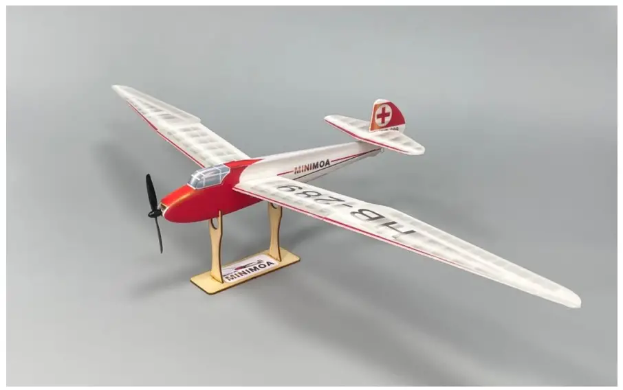
MinimumRC SFHSS-B Minimoa Glider Gull Wing 700mm Micro RC Aircraft Kit
Contents
Important notification
- The model is supplied with UFO and 502 glue. UFO is for bonding foam parts, and 502 for bonding wood, carbon fiber and metal parts. 502 glue will cause serious corrosion to foam parts.
- Please wait for the glue to dry and solidify in each installation step before the next installation.
- Please avoid using flame to heat the heat shrinkable tube on the model. Electric iron shall be used for heating
- Please use razor blade to remove the parts from the plate. Do not tear the parts by force.
Assembly Instructions
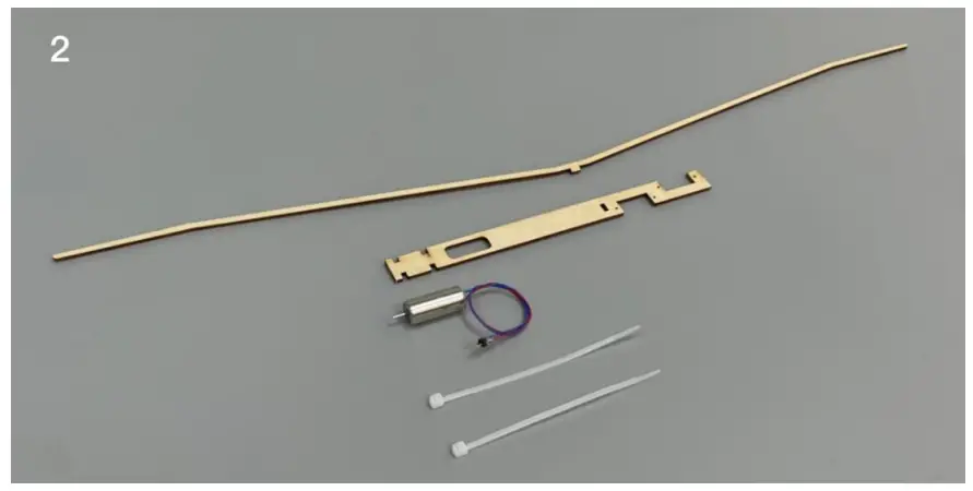
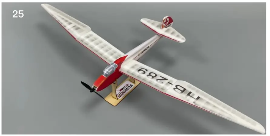
- assemble the wooden base

- Wooden parts of the fuselage.
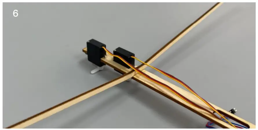
- Assemble the wooden parts of the fuselage. Please pay attention to the opening direction of the servo base and do not reverse it.
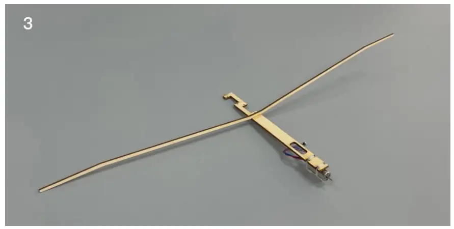
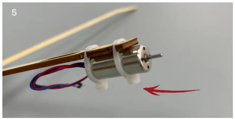
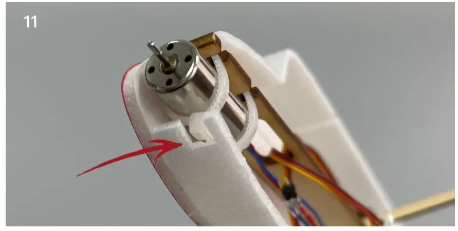
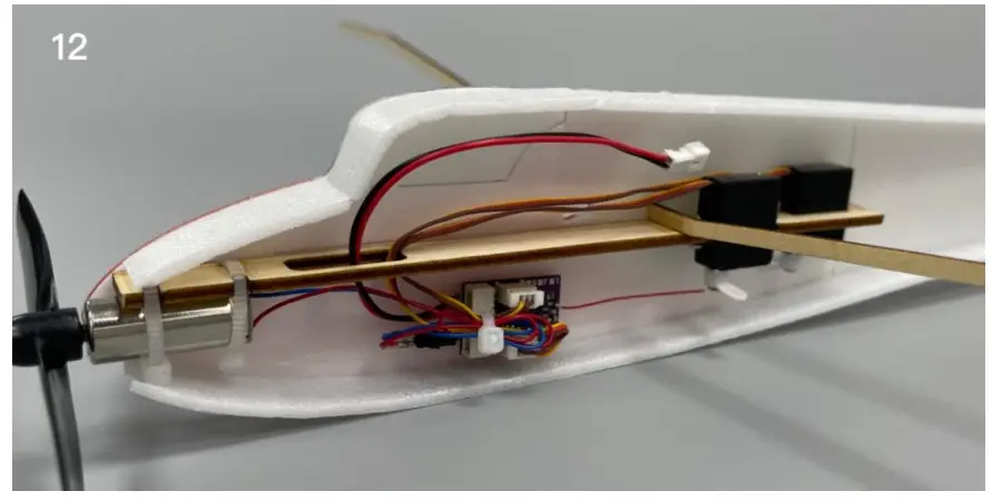
- fix the motor with a tie, and the fixed end of the tie should be just at the bottom. After fixing, 502 glue shall be applied to the side for reinforcement.

- Details.
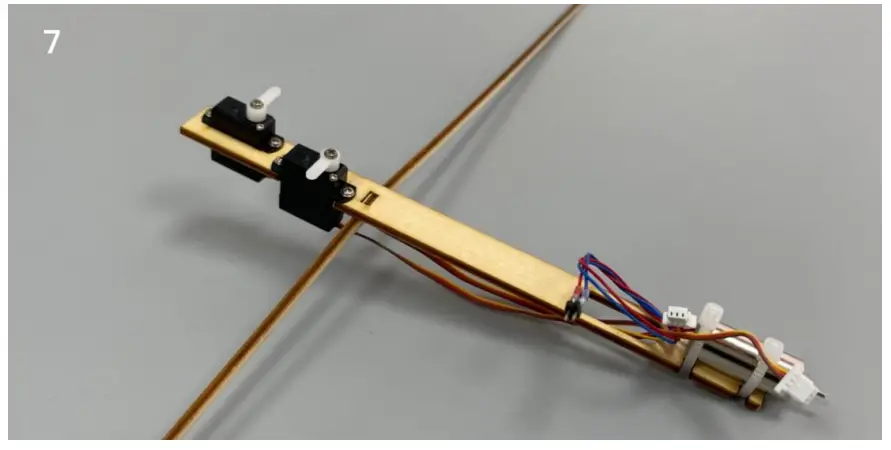
- Connect the servos to a powered receiver. Bind the receiver with your transmitter to make the servos arms return to their neutral point. Test whether the servos are working correctly, and install the servo arms according to the position shown in the picture. Note: Please make sure that the servos have been tested and installed in strict accordance with the following picture. After assembling the model, it will be not able to adjust.
- (bottom view) The servos are installed and fixed under the plywood board
- Align the scribed line on the inner side of the fuselage and fix the wooden s tructure with glue.

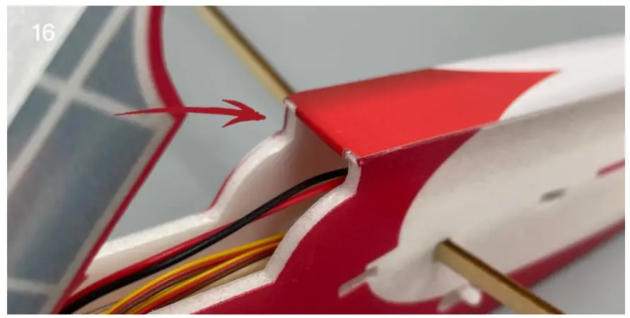
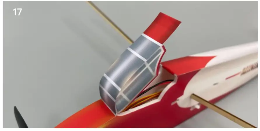
- Press the top and bottom strip of the fuselage and bend them into the corresponding shape of the fuselage.
- Fix the top and bottom strip of the fuselage with glue.

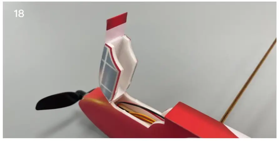
- Details: cut off the position where the fuselage side strip interferes with the tie.
- Fix the receiver with Velcro, connect the cables, and fix the cables with tie. The power wire shall pass through the hole on the wooden part and be placed on the upper part of the fuselage. Test whether the servos and motor are working correctly.
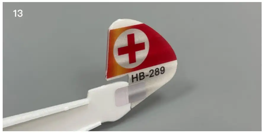
- Fix the vertical tail with stickers.
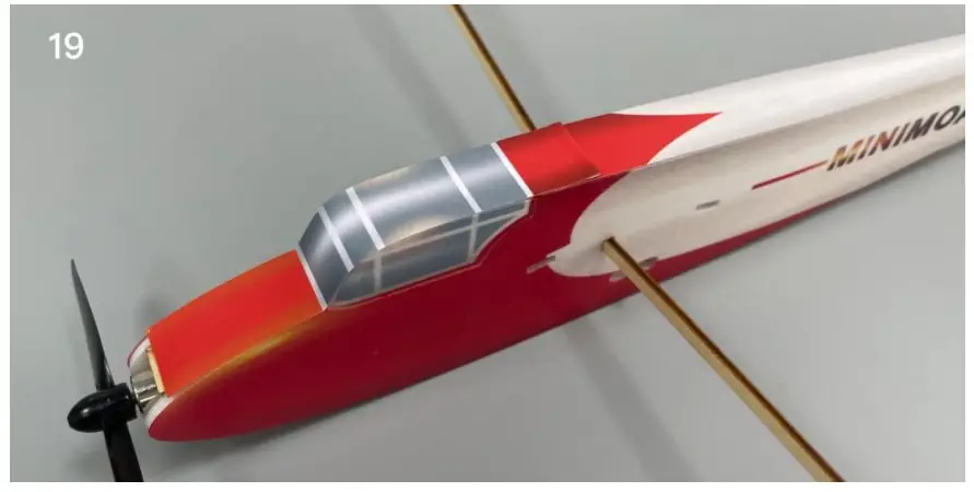
- Combine the fuselage.
- Paste the fuselage sticker.

- Paste the fuselage sticker.
- Paste the fuselage sticker.
- Paste the fuselage sticker.
- Paste the fuselage sticker.
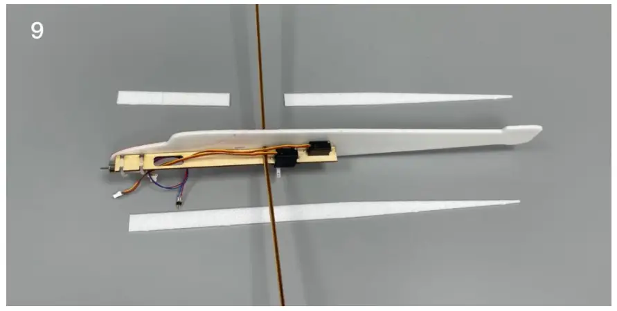
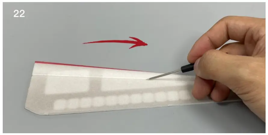
- Use the end of a screw driver to score through the half-cut line of the horizontal tail surface.
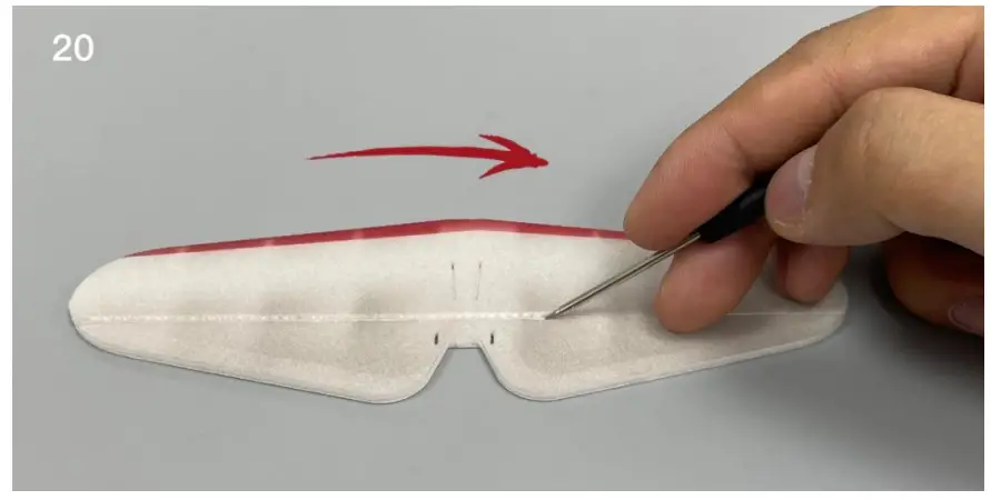
- Use the end of a screw driver to score through the half-cut line of the wings.

- Use the end of a screw driver to score through the half-cut line of the wings.
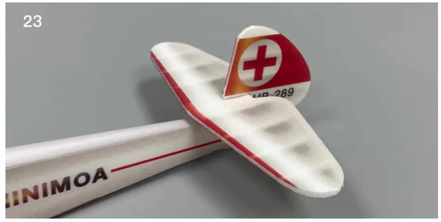
- Install the tail.
- Attach the inner part of the wings to the fuselage.
- Attach the outer part of the wings.
- Details: attach the outer part of the wings.

- Install rudder control horns.
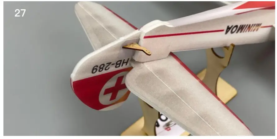
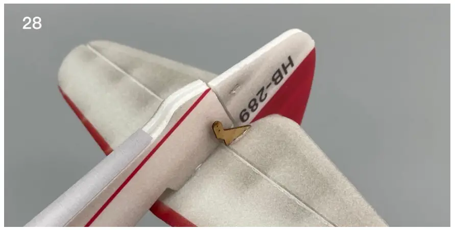
- Install elevator control horns.
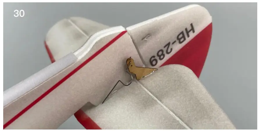
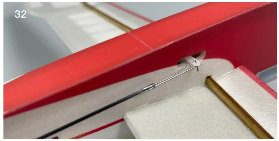
- Attach the steel wire hook to the control horns.

- Attach the steel wire hook to the control horns.
- Use heat shrinkable tube to connect the push rod and wire clip, then use glue to fix them.
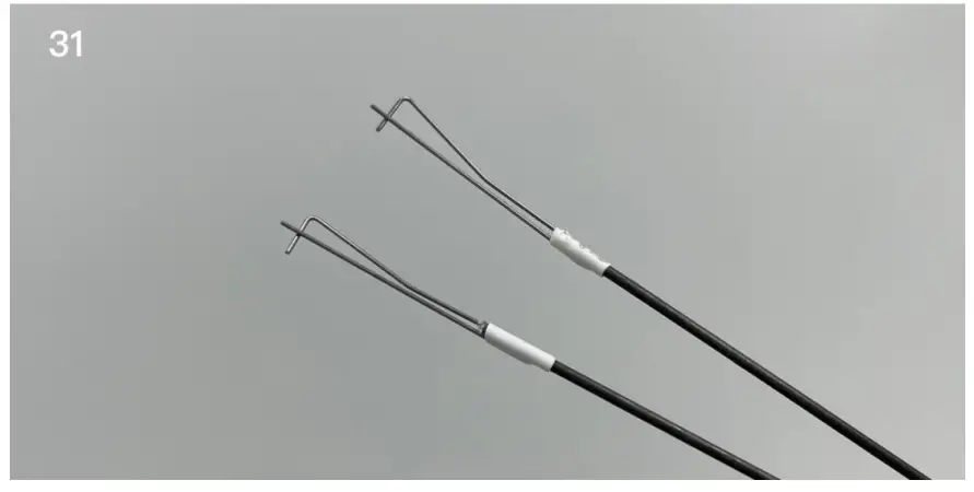
- Attach the push rods to the servo arms.
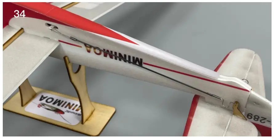
- Connect the steel wire hook and the push rods with heat-shrinkable tube.
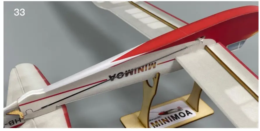
- Connect the steel wire hook and the push rods with heat-shrinkable tube.
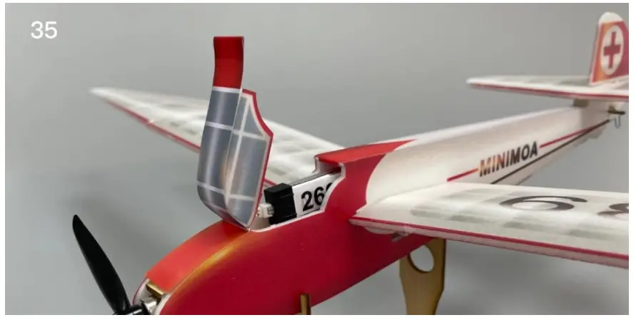
- The battery is directly placed in the cabin.
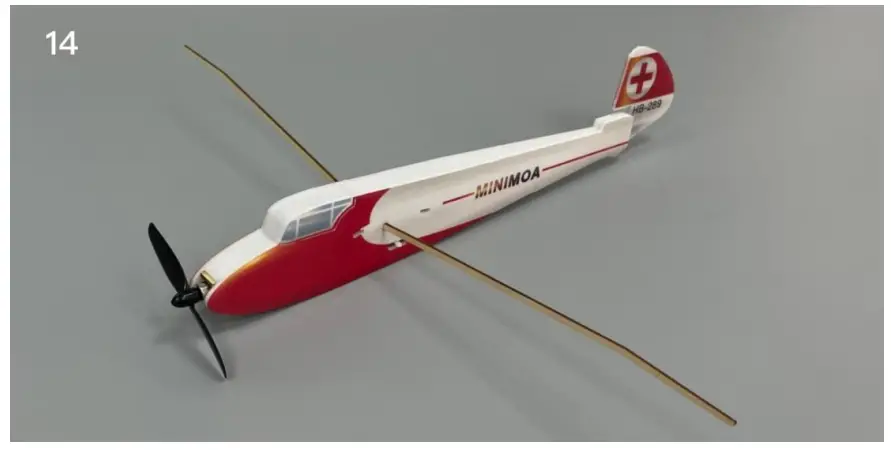
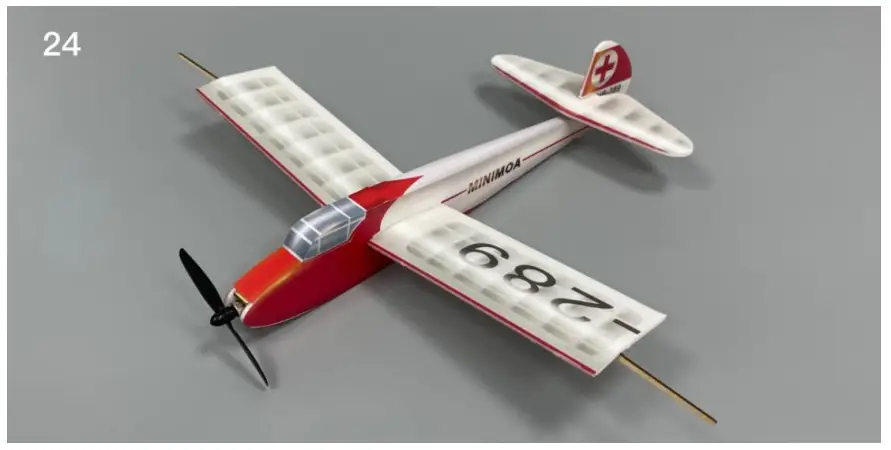
Assembly complete!
Maiden flight
- The center of gravity of the aircraft is located at 5mm in front of the score line on the wing.
- The active range of elevator and rudder is 5mm on both sides.
- Test glide on grass land before powered flight.
- Choose grass land with hand launch for maiden flight.