Contents
MEAN WELL NCP-3200 Series 2 In 1 Rack Mounted Switching Power Supply

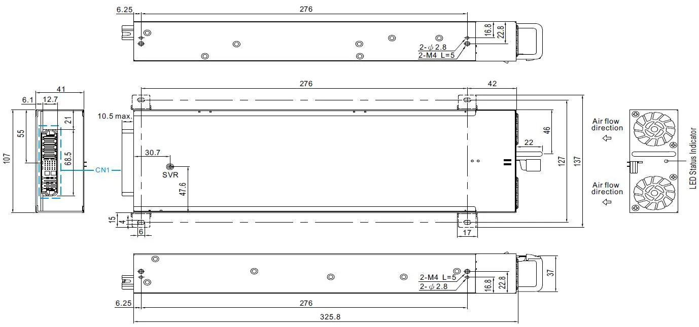
Dimension
- L * W * H
- 325.8 * 107 * 41 (1U) mm
- 12.82 * 4.21 * 1.61 (1U) inch
Features
- Universal AC input / Full range
- Power supply or charger mode selectable by PMBus, CANBus or SBP-001 (only for 24V/48V models)
- Built-in 2/3 stage charging curves and programmable curve (only for 24V/48V models)
- High efficiency up to 94.5%
- Built-in programmable output voltage and output current
- Built-in OR-ing FET or Diode, support hot swap (hot plug)
- Active current sharing up to 10 rack shelves and the maximum power supply that can be connected in parallel is 40 units
- Support PMBus/CANBus protocol
- Built-in intelligent fan speed control
- Protections: Short circuit / Overload / Over voltage /Over temperature
- Design refers to SEMI F47 standard specification
- 5 years warranty
Applications
- Industrial automation
- Distributed power architecture system
- Wireless/telecommunication solution
- Redundant power system
- Large-scale DC UPS or emergency backup system
- Electric scooter or vehicle charger station
- Wastewater treatment system
- Electrolysis system
GTIN CODE
- MW Search: https://www.meanwell.com/serviceGTIN.aspx.
Description
- NCP-3200 is a 3.2KW dual-purpose(Switching Power Supply and charger) rack-mounted AC/DC power supply with a 1U low profile design and high power density of up to 37W/inch. This series operates at 90~264VAC input voltage and offers the models with the DC output mostly demanded by the industry.
- Each model is cooled by the built-in DC fan with fan speed control and working for the temperature up to 70°C. NCP-3200 provides vast design flexibility by equipping with PMBus and CANbus, two international communication protocols that can be selected for industrial control and power supply control, and can also be used directly with intelligent controller CMU2. Active current sharing up to 10 rack shelves (DHP-1UT-B) and the maximum power supply that can be connected in parallel is 40 units, remote ON/OFF control, auxiliary power, alarm signal, and others.
Model Encoding / Order Information
Note 1: 19″ rack shelf, DHP-1UT-B(HV), available. Details available on https://www.meanwell.com/
Note 2: Control/Monitor unit, CMU2, available. Details available on https://www.meanwell.com/
| Type | Communication Protocol | Note |
| Blan | PMBus protocol | In Stock |
| CAN | CANBus protocol | In Stock |
SPECIFICATION FOR POWER SUPPLY MODE (Default)
| MODEL | NCP-3200-24 | NCP-3200-48 | |||
|
OUTPUT |
DC VOLTAGE (factory default) | 24V | 48V | ||
| RATED CURRENT (factory default) | 133A | 67A | |||
| CURRENT RANGE | 0 ~ 133A | 0 ~ 67A | |||
| RATED POWER (max.) | 3192W | 3216W | |||
| RIPPLE & NOISE (max.) Note.2,3 | 300mVp-p | 480mVp-p | |||
| VOLTAGE ADJ. RANGE | 23.5 ~ 30V | 47.5 ~ 58.8V | |||
| VOLTAGE TOLERANCE Note.4 | ±1.0% | ±1.0% | |||
| LINE REGULATION | ±0.5% | ±0.5% | |||
| LOAD REGULATION | ±0.5% | ±0.5% | |||
| SETUP, RISE TIME | 1500ms, 60ms/230VAC at full load | ||||
| HOLD UP TIME (Typ.) | 16ms / 230VAC at 70% load 8ms / 230VAC at full load | ||||
|
INPUT |
VOLTAGE RANGE Note.6 | 90 ~ 264VAC 127 ~ 400VDC | |||
| FREQUENCY RANGE | 47 ~ 63Hz | ||||
| POWER FACTOR (Typ.) | 0.97/230VAC at full load | ||||
| EFFICIENCY (Typ.) Note.7 | 93.5% | 94.5% | |||
| AC CURRENT (Typ.) Note.6 | 17A/230VAC | ||||
| INRUSH CURRENT (Typ.) | COLD START 55A/230VAC | ||||
| LEAKAGE CURRENT | <2mA / 230VAC | ||||
|
PROTECTION |
OVERLOAD |
105 ~ 115% rated current | |||
| Protection type: Constant current limiting, shut down O/P voltage after 5 sec. After the O/P voltage falls, re-power on to recover | |||||
|
OVERVOLTAGE |
31.5 ~ 37.5V | 63 ~ 75V | |||
| Protection type: Shut down o/p voltage, re-power on to recover | |||||
| OVER TEMPERATURE | Shut down o/p voltage, recovers automatically after temperature goes down | ||||
|
FUNCTION |
OUTPUT VOLTAGE
PROGRAMMABLE(PV) |
Adjustment of the output voltage is allowable to 50 ~ 125% of nominal output voltage Please refer to the Function Manual in the following pages | |||
| CONSTANT CURRENT LEVEL PROGRAMMABLE(PC) | Adjustment of the constant current level is allowable to 20 ~ 100% of rated current Please refer to the Function Manual in the following pages | ||||
| REMOTE ON-OFF CONTROL | By electrical signal or dry contact Power ON: short Power OFF: open. Please refer to the Function Manual in the following pages | ||||
| REMOTE SENSE | Compensate voltage drop on the load wiring up to 0.5V. Please refer to the Function Manual in the following pages | ||||
| CURRENT SHARING | Active current sharing up to 10 rack shelves(DHP-1UT-B) and the maximum number of supply units that can be connected in parallel is 40 | ||||
| AUXILIARY POWER | 5V @ 0.3A, tolerance ±10%, ripple 150mVp-p, 12V @ 0.8A, tolerance ±10%, ripple 450mVp-p | ||||
| ALARM SIGNAL | Isolated TTL signal output for T-Alarm, AC-OK and DC-OK. Please refer to the Function Manual in the following pages | ||||
|
ENVIRONMENT |
WORKING TEMP. | -30 ~ +70℃ (Refer to “Derating Curve”) | |||
| WORKING HUMIDITY | 20 ~ 90% RH non-condensing | ||||
| STORAGE TEMP., HUMIDITY | -40 ~ +85℃, 10 ~ 95% RH non-condensing | ||||
| TEMP. COEFFICIENT | ±0.03%/℃ (0 ~ 50℃) | ||||
| VIBRATION | 10 ~ 500Hz, 2G 10min./1cycle, 60min. each along X, Y, and Z axes | ||||
|
SAFETY & EMC (Note 10) |
SAFETY STANDARDS | UL62368-1, CSA C22.2 No. 62368-1, TUV BS EN/EN62368-1, EAC TP TC 004 approved ; Design refer to AS/NZS62368.1 | |||
| WITHSTAND VOLTAGE | I/P-O/P:3KVAC I/P-FG:2KVAC O/P-FG:1.5KVAC | ||||
| ISOLATION RESISTANCE | I/P-O/P, I/P-FG, O/P-FG:100M Ohms / 500VDC / 25℃/ 70% RH | ||||
|
EMC EMISSION |
Parameter | Standard | Test Level / Note | ||
| Conducted | BS EN/EN55032 (CISPR32) | Class B | |||
| Radiated | BS EN/EN55032 (CISPR32) | Class A | |||
| Harmonic Current | BS EN/EN61000-3-2 | Class A | |||
| Voltage Flicker | BS EN/EN61000-3-3 | —– | |||
|
EMC IMMUNITY |
BS EN/EN55024, BS EN/EN61000-6-2; Design refer to SEMI F47 at 200VAC | ||||
| Parameter | Standard | Test Level / Note | |||
| END | BS EN/EN61000-4-2 | Level 3, 8KV air ; Level 2, 4KV contact | |||
| Radiated | BS EN/EN61000-4-3 | Level 3 | |||
| EFT / Burst | BS EN/EN61000-4-4 | Level 3 | |||
| Surge | BS EN/EN61000-4-5 | 2KV/Line-Line 4KV/Line-Earth | |||
| Conducted | BS EN/EN61000-4-6 | Level 3 | |||
| Magnetic Field | BS EN/EN61000-4-8 | Level 4 | |||
| Voltage Dips and Interruptions | BS EN/EN61000-4-11 | >95% dip 0.5 periods, 30% dip 25 periods,
>95% interruptions 250 periods |
|||
|
OTHERS |
MTBF | 510.5K hrs min. Telcordia SR-332 (Bellcore); 45.8K hrs min. MIL-HDBK-217F (25℃) | |||
| DIMENSION | 325.8*107*41mm (L*W*H) | ||||
| PACKING | 2.3Kg;4pcs/10.2Kg/1.09CUFT | ||||
| NOTE | 1. All parameters NOT specially mentioned are measured at 230VAC input, rated load and 25℃ of ambient temperature.
2. Ripple & noise are measured at 20MHz of bandwidth by using a 12″ twisted pair-wire terminated with a 0.1uf & 47uf parallel capacitor. 3. Under variable load application or parallel operation ripple of the output voltage may be higher than the SPEC at light load conditions. It will go back to normal ripple level once the output load is more than 5%. 4. Tolerance: includes set up tolerance, line regulation and load regulation. 5. RCM is on a voluntary basis and meets relevant IEC or AS/NZS standards complying with AS/NES 4417.1. 6. Derating may be needed under low input voltages. Please check the derating curve for more details. 7. The efficiency is measured at 75% load. 8. If use PV signal to adjust Vo, under certain operating conditions, the ripple noise of Vo might slightly go over the rating defined in this specification. 9. Output will shut down after O/P voltage is below < 80% of Vset for 5 sec, re-power on to recover. 10. The power supply is considered a component that will be installed into the final equipment. All the EMC tests are been executed by mounting the unit on a 600mm*900mm metal plate with 1mm of thickness. The final equipment must be re-confirmed that it still meets EMC directives. For guidance on how to perform these EMC tests, please refer to “EMI testing of component power supplies.” (as available on https://www.meanwell.com) 11. The ambient temperature derating of 3.5℃/1000m with fanless models and of 5℃/1000m with fan models for operating altitudes higher than 2000m(6500ft). ※ Product Liability Disclaimer: For detailed information, please refer to https://www.meanwell.com/serviceDisclaimer.aspx |
||||
| MODEL | NCP-3200-380 | |||
|
OUTPUT |
DC VOLTAGE (factory default) | 380V | ||
| CURRENT (factory default) | 8.4A | |||
| CURRENT RANGE | 0 ~ 9.6A | |||
| RATED POWER (max.) | 3206.4W | |||
| FULL POWER VOLTAGE RANGE | 334 ~ 400V | |||
| RIPPLE & NOISE (max.) Note.2,3 | 4000mVp-p | |||
| VOLTAGE ADJ. RANGE | 260 ~ 400V | |||
| VOLTAGE TOLERANCE Note.4 | ±1.0% | |||
| LINE REGULATION | ±0.5% | |||
| LOAD REGULATION | ±0.5% | |||
| SETUP, RISE TIME | 1500ms, 60ms/230VAC at full load | |||
| HOLD UP TIME (Typ.) | 16ms / 230VAC at 70% load 8ms / 230VAC at full load | |||
|
INPUT |
VOLTAGE RANGE Note.6 | 90 ~ 264VAC 127 ~ 400VDC | ||
| FREQUENCY RANGE | 47 ~ 63Hz | |||
| POWER FACTOR (Typ.) | 0.97/230VAC at full load | |||
| EFFICIENCY (Typ.) Note.7 | 94% | |||
| AC CURRENT (Typ.) Note.6 | 17A/230VAC | |||
| INRUSH CURRENT (Typ.) | COLD START 55A/230VAC | |||
| LEAKAGE CURRENT | <2mA / 230VAC | |||
|
PROTECTION |
OVERLOAD |
105 ~ 115% rated current | ||
| Protection type: Constant current limiting, shut down O/P voltage after 5 sec. After the O/P voltage falls, re-power on to recover | ||||
|
OVERVOLTAGE |
420 ~ 480V | |||
| Protection type: Shut down o/p voltage, re-power on to recover | ||||
| OVER TEMPERATURE | Shut down o/p voltage, recovers automatically after temperature goes down | |||
|
FUNCTION |
OUTPUT VOLTAGE
PROGRAMMABLE(PV) |
Adjustment of the output voltage is allowable to 50 ~ 120% of nominal output voltage Please refer to the Function Manual in the following pages | ||
| CONSTANT CURRENT LEVEL PROGRAMMABLE(PC) | Adjustment of the constant current level is allowable to 20 ~ 100% of the rated current Please refer to the Function Manual on the following pages | |||
| REMOTE ON-OFF CONTROL | By electrical signal or dry contact Power ON: short Power OFF: open. Please refer to the Function Manual in the following pages | |||
| CURRENT SHARING | Active current sharing up to 10 rack shelves(DHP-1UT-BHV) and the maximum number of supply units that can be connected in parallel is 40 | |||
| AUXILIARY POWER | 5V @ 0.3A, tolerance ±10%, ripple 150mVp-p, 12V @ 0.8A, tolerance ±10%, ripple 450mVp-p | |||
| ALARM SIGNAL | Isolated TTL signal output for T-Alarm, AC-OK and DC-OK. Please refer to the Function Manual in the following pages | |||
|
ENVIRONMENT |
WORKING TEMP. | -30 ~ +70℃ (Refer to “Derating Curve”) | ||
| WORKING HUMIDITY | 20 ~ 90% RH non-condensing | |||
| STORAGE TEMP., HUMIDITY | -40 ~ +85℃, 10 ~ 95% RH non-condensing | |||
| TEMP. COEFFICIENT | ±0.03%/℃ (0 ~ 50℃) | |||
| VIBRATION | 10 ~ 500Hz, 2G 10min./1cycle, 60min. each along X, Y, and Z axes | |||
|
SAFETY & EMC (Note 10) |
SAFETY STANDARDS | UL62368-1, CSA C22.2 No. 62368-1, TUV BS EN/EN62368-1, EAC TP TC 004 approved ; Design refer to AS/NZS62368.1 | ||
| WITHSTAND VOLTAGE | I/P-O/P:3KVAC I/P-FG:2KVAC O/P-FG:1.5KVAC | |||
| ISOLATION RESISTANCE | I/P-O/P, I/P-FG, O/P-FG:100M Ohms / 500VDC / 25℃/ 70% RH | |||
|
EMC EMISSION |
Parameter | Standard | Test Level / Note | |
| Conducted | BS EN/EN55032 (CISPR32) | Class B | ||
| Radiated | BS EN/EN55032 (CISPR32) | Class A | ||
| Harmonic Current | BS EN/EN61000-3-2 | Class A | ||
| Voltage Flicker | BS EN/EN61000-3-3 | —– | ||
|
EMC IMMUNITY |
BS EN/EN55024, BS EN/EN61000-6-2; Design refer to SEMI F47 at 200VAC | |||
| Parameter | Standard | Test Level / Note | ||
| END | BS EN/EN61000-4-2 | Level 3, 8KV air ; Level 2, 4KV contact | ||
| Radiated | BS EN/EN61000-4-3 | Level 3 | ||
| EFT / Burst | BS EN/EN61000-4-4 | Level 3 | ||
| Surge | BS EN/EN61000-4-5 | 2KV/Line-Line 4KV/Line-Earth | ||
| Conducted | BS EN/EN61000-4-6 | Level 3 | ||
| Magnetic Field | BS EN/EN61000-4-8 | Level 4 | ||
| Voltage Dips and Interruptions | BS EN/EN61000-4-11 | >95% dip 0.5 periods, 30% dip 25 periods,
>95% interruptions 250 periods |
||
|
OTHERS |
MTBF | 510.5K hrs min. Telcordia SR-332 (Bellcore); 45.8K hrs min. MIL-HDBK-217F (25℃) | ||
| DIMENSION | 325.8*107*41mm (L*W*H) | |||
| PACKING | 2.3Kg;4pcs/10.2Kg/1.09CUFT | |||
| NOTE | 1. All parameters NOT specially mentioned are measured at 230VAC input, rated load and 25℃ of ambient temperature.
2. Ripple & noise are measured at 20MHz of bandwidth by using a 12″ twisted pair-wire terminated with a 0.1uf & 47uf parallel capacitor. 3. Under variable load application or parallel operation ripple of the output voltage may be higher than the SPEC at light load conditions. It will go back to normal ripple level once the output load is more than 5%. 4. Tolerance: includes set up tolerance, line regulation and load regulation. 5. RCM is on a voluntary basis and meets relevant IEC or AS/NZS standards complying with AS/NES 4417.1. 6. Derating may be needed under low input voltages. Please check the derating curve for more details. 7. The efficiency is measured at 75% load. 8. If use PV signal to adjust Vo, under certain operating conditions, the ripple noise of Vo might slightly go over the rating defined in this specification. 9. Output will shut down after O/P voltage is below < 80% of Vset for 5 sec, re-power on to recover. 10. The power supply is considered a component that will be installed into the final equipment. All the EMC tests are been executed by mounting the unit on a 600mm*900mm metal plate with 1mm of thickness. The final equipment must be re-confirmed that it still meets EMC directives. For guidance on how to perform these EMC tests, please refer to “EMI testing of component power supplies.” (as available on https://www.meanwell.com) 11. The ambient temperature derating of 3.5℃/1000m with fanless models and of 5℃/1000m with fan models for operating altitudes higher than 2000m(6500ft). ※ Product Liability Disclaimer: For detailed information, please refer to https://www.meanwell.com/serviceDisclaimer.aspx |
|||
SPECIFICATION FOR CHARGER MODE (Selectable by PMBus, CANBus or SBP-001)
| MODEL | NCP-3200-24 | NCP-3200-48 | |||
|
OUTPUT |
BOOST CHARGE VOLTAGE(Vboost)(default) | 28.8V | 57.6V | ||
| FLOAT CHARGE VOLTAGE(Vfloat)(default) | 27.6V | 55.2V | |||
| CONSTANT CURRENT(CC)(default) | 110A | 55A | |||
| RECOMMENDED BATTERY
CAPACITY(AMP HOURS) Note.3 |
330 ~ 1000Ah |
180 ~ 550Ah |
|||
| LEAKAGE CURRENT FROM BATTERY(Typ.) |
<1.5mA |
||||
|
INPUT |
VOLTAGE RANGE Note.4 | 90 ~ 264VAC 127 ~ 400VDC | |||
| FREQUENCY RANGE | 47 ~ 63Hz | ||||
| POWER FACTOR (Typ.) | 0.97/230VAC at full load | ||||
| EFFICIENCY (Typ.) | 93% | 94% | |||
| AC CURRENT (Typ.) Note.4 | 17A/230VAC | ||||
| INRUSH CURRENT (Typ.) | COLD START 55A/230VAC | ||||
| LEAKAGE CURRENT | <2mA / 230VAC | ||||
|
PROTECTION |
OVERVOLTAGE |
31.5 ~ 37.5V | 63 ~ 75V | ||
| Protection type: Shut down o/p voltage, re-power on to recover | |||||
| OVER TEMPERATURE | Shut down o/p voltage, recovers automatically after temperature goes down | ||||
|
FUNCTION |
REMOTE ON-OFF CONTROL | By electrical signal or dry contact Power ON: short Power OFF: open. Please refer to the Function Manual in the following pages | |||
| CURRENT SHARING | Active current sharing up to 10 rack shelves(DHP-1UT-B) and the maximum number of supply units that can be connected in parallel is 40 | ||||
| AUXILIARY POWER | 5V @ 0.3A, tolerance ±10%, ripple 150mVp-p, 12V @ 0.8A, tolerance ±10%, ripple 450mVp-p | ||||
| ALARM SIGNAL | Isolated TTL signal output for T-Alarm, AC-OK and DC-OK. Please refer to the Function Manual on the following pages | ||||
|
ENVIRONMENT |
WORKING TEMP. | -30 ~ +70℃ (Refer to “Derating Curve”) | |||
| WORKING HUMIDITY | 20 ~ 90% RH non-condensing | ||||
| STORAGE TEMP., HUMIDITY | -40 ~ +85℃, 10 ~ 95% RH non-condensing | ||||
| TEMP. COEFFICIENT | ±0.03%/℃ (0 ~ 50℃) | ||||
| VIBRATION | 10 ~ 500Hz, 2G 10min./1cycle, 60min. each along X, Y, and Z axes | ||||
|
SAFETY & EMC (Note 6) |
SAFETY STANDARDS | UL62368-1, CSA C22.2 No. 62368-1, TUV BS EN/EN62368-1, EAC TP TC 004 approved ; Design refer to AS/NZS62368.1 | |||
| WITHSTAND VOLTAGE | I/P-O/P:3KVAC I/P-FG:2KVAC O/P-FG:1.5KVAC | ||||
| ISOLATION RESISTANCE | I/P-O/P, I/P-FG, O/P-FG:100M Ohms / 500VDC / 25℃/ 70% RH | ||||
|
EMC EMISSION |
Parameter | Standard | Test Level / Note | ||
| Conducted | BS EN/EN55032 (CISPR32) | Class B | |||
| Radiated | BS EN/EN55032 (CISPR32) | Class A | |||
| Harmonic Current | BS EN/EN61000-3-2 | Class A | |||
| Voltage Flicker | BS EN/EN61000-3-3 | —– | |||
|
EMC IMMUNITY |
BS EN/EN55024, BS EN/EN61000-6-2 | ||||
| Parameter | Standard | Test Level / Note | |||
| END | BS EN/EN61000-4-2 | Level 3, 8KV air ; Level 2, 4KV contact | |||
| Radiated | BS EN/EN61000-4-3 | Level 3 | |||
| EFT / Burst | BS EN/EN61000-4-4 | Level 3 | |||
| Surge | BS EN/EN61000-4-5 | 2KV/Line-Line 4KV/Line-Earth | |||
| Conducted | BS EN/EN61000-4-6 | Level 3 | |||
| Magnetic Field | BS EN/EN61000-4-8 | Level 4 | |||
| Voltage Dips and Interruptions | BS EN/EN61000-4-11 | >95% dip 0.5 periods, 30% dip 25 periods,
>95% interruptions 250 periods |
|||
|
OTHERS |
MTBF | 510.5K hrs min. Telcordia SR-332 (Bellcore); 45.8K hrs min. MIL-HDBK-217F (25℃) | |||
| DIMENSION | 325.8*107*41mm (L*W*H) | ||||
| PACKING | 2.3Kg;4pcs/10.2Kg/1.09CUFT | ||||
| NOTE | 1. Modification for charger specification may be required for different battery specifications. Please contact the battery vendor and MEAN WELL for details.
2. All parameters NOT specially mentioned are measured at 230VAC input, rated load and 25℃ of ambient temperature. 3. This is MEAN WELL’s suggested range. Please consult your battery manufacturer for their suggestions about the maximum charging current limitation. 4. Derating may be needed under low input voltages. Please check the derating curve for more details. 5. RCM is on a voluntary basis and meets relevant IEC or AS/NZS standards complying with AS/NES 4417.1. 6. The charger is considered a component that will be installed into the final equipment. All the EMC tests are been executed by mounting the unit on a 600mm*900mm metal plate with 1mm of thickness. The final equipment must be re-confirmed that it still meets EMC directives. For guidance on how to perform these EMC tests, please refer to “EMI testing of component power supplies.” (as available on https://www.meanwell.com) 7. The ambient temperature derating of 3.5℃/1000m with fanless models and of 5℃/1000m with fan models for operating altitudes higher than 2000m(6500ft). ※ Product Liability Disclaimer: For detailed information, please refer to https://www.meanwell.com/serviceDisclaimer.aspx |
||||
BLOCK DIAGRAM
STATIC CHARACTERISTICS
DERATING LOADS vs INPUT VOLTAGE
| MODEL
INPUT |
24V | 48V | 380V |
|
180~264VAC |
3192W
133A |
3216W
67A |
3192W
8.4A |
|
90VAC |
1596W
66.5A |
1608W
33.5A |
1596W
4.2A |
DERATING CURVE
EFFICIENCY vs LOAD (48V MODEL)
FUNCTION MANUAL
Charging Curve (Charger mode only available for 24V/48V models)
- By default, the unit operates in power supply mode, and it can be configured to charger mode by PMBus, CANBus or SBP-001.
- By factory default, this charger performs the default curve which can be programmed via PMBus and CANBus.
- To accommodate the parameters of the charging curve, SBP-001, the smart battery charging programmer designed by MEAN WELL, and a personal computer are needed. Please contact MEAN WELL for details.
| State | NCP-3200-24 | NCP-3200-48 |
| Constant Current |
110A |
55A |
| Vboost | 28.8V | 57.6V |
- Suitable for lead-acid batteries (flooded, Gel and AGM) and Li-ion batteries (lithium iron and lithium manganese).
| State | NCP-3200-24 | NCP-3200-48 |
| Constant Current |
110A |
55A |
| Vboost | 28.8V | 57.6V |
| Vfloat | 27.6V | 55.2V |
- Suitable for lead-acid batteries (flooded, Gel and AGM) and Li-ion batteries (lithium iron and lithium manganese).
- Embedded 2-stage charging curves
| MODEL | Description | CC(default) | Vboost |
|
24V |
Default, programmable |
110A |
28.8 |
| Pre-defined, gel battery | 28 | ||
| Pre-defined, flooded battery | 28.4 | ||
| Pre-defined, AGM battery | 29 | ||
|
48V |
Default, programmable |
55A |
57.6 |
| Pre-defined, gel battery | 56 | ||
| Pre-defined, flooded battery | 56.8 | ||
| Pre-defined, AGM battery | 58 |
Embedded 3-stage charging curves
| MODEL | Description | CC(default) | Vboost | Vfloat |
|
24V |
Default, programmable |
110A |
28.8 | 27.6 |
| Pre-defined, gel battery | 28 | 27.2 | ||
| Pre-defined, flooded battery | 28.4 | 26.8 | ||
| Pre-defined, AGM battery | 29 | 27 | ||
|
48V |
Default, programmable |
55A |
57.6 | 55.2 |
| Pre-defined, gel battery | 56 | 54.4 | ||
| Pre-defined, flooded battery | 56.8 | 53.6 | ||
| Pre-defined, AGM battery | 58 | 54 |
Front Panel LED Indicators
Voltage Drop Compensation
- Remote Sense (For 24V/48V models under power supply mode only)
- The Remote Sense compensates for voltage drop on the load wiring up to 0.5V
Local Sense (For 24V/48V models under power supply mode only)
- The +S and and-S have to be connected to the +V(signal), and -V(signal), respectively, as the following diagram, in order to get the correct output voltage if Remote Sense is not used.
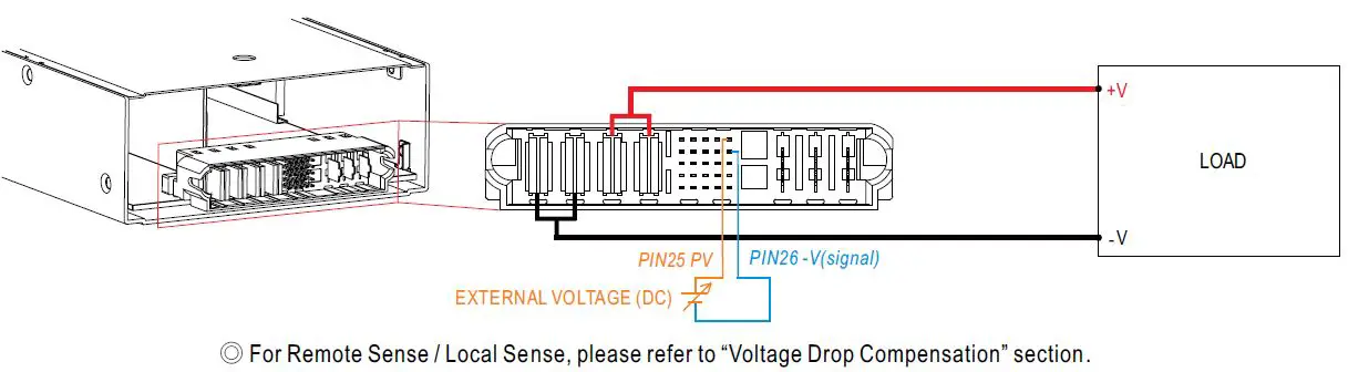
Output Voltage Programming (or, PV / remote voltage programming / remote adjust / margin programming / dynamic voltage trim)
- In addition to the adjustment via the built-in potentiometer, the output voltage can be trimmed to 50~125% (24/48V models) or 50~120% (380V model) of the nominal voltage by applying EXTERNAL VOLTAGE.
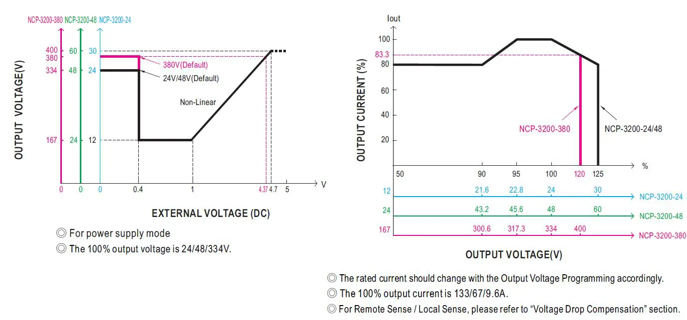
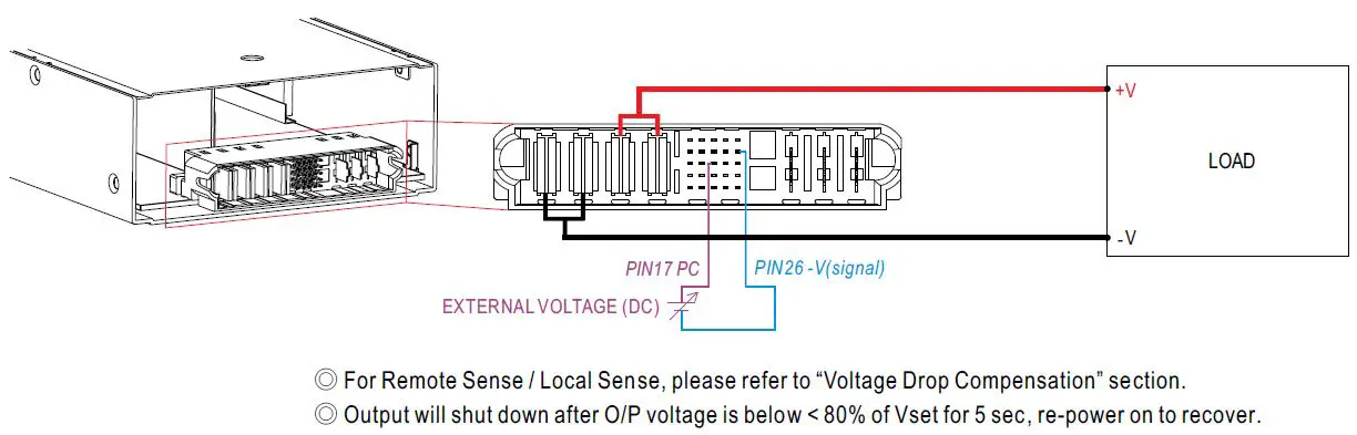
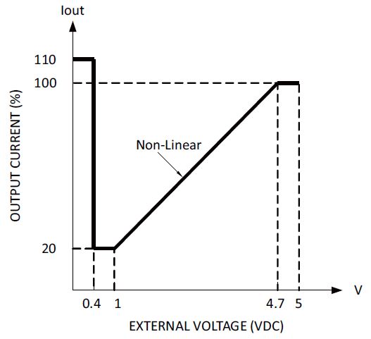
Constant Current Level Programming (or, PC / remote current programming / dynamic current trim)
- The constant current level can be trimmed to 20~100% of the rated current by applying EXTERNAL VOLTAGE.
- If setting the output current to a much lower level, as output status turns to the constant current mode, it might cause a higher current ripple under such conditions.
- The 100% output current is 133/67/9.6A.
- Notice the output power does not overrate power (max.)
Remote ON-OFF Control
- The power supply can be turned ON/OFF individually or along with other units by using the “Remote ON-OFF” function.
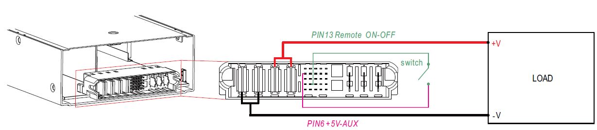
| Between Remote ON-OFF and +5V-AUX | Power Supply Status |
| Switch Short | ON |
| Switch Open | OFF |
PMBus Communication Interface
NCP-3200 supports PMBus Rev. 1.1 with a maximum 100KHz bus speed, allowing information reading, status monitoring, output trimming, etc. For details, please refer to the Function Manual.
CANBus Communication Interface
NCP-3200 supports CAN 2.0B with a maximum 250KHz bus speed, allowing information reading, status monitoring, output trimming, etc. For details, please refer to the User’s Manual.
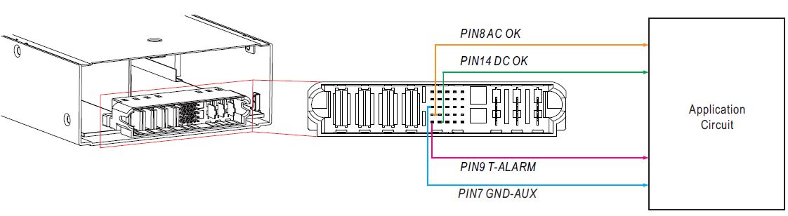
Alarm Signal Output
* There are 3 alarm signals, DC-OK, AC-OK and T-ALARM, in TTL signal form, on CN1. These signals are isolated from the output. The maximum sink current is 10mA.
| DC-OK signal | Power Supply Mode Status | Charger Mode Status |
| “High” > 3.5~5.5V | Vout ≦ 77%±5% | Vout ≦ 66%±5% |
| “Low” < -0.5~0.5V | Vout ≧ 80%±5% | Vout ≧ 67%±5% |
| AC-OK signal | Power Supply and Charger Mode Status |
| “High” > 3.5~5.5V | Input voltage ≧ 87Vrms |
| “Low” < -0.5~0.5V | Input voltage ≦ 75Vrms |
| T-ALARM signal | Power Supply and Charger Mode Status |
| “High” > 3.5~5.5V | OFF(OTP or Fan Fail) |
| “Low” < -0.5~0.5V | ON(Normal Work) |
Parallel Operation
- For parallel operation, please refer to the function manual of the DHP-1UT-B(HV) rack system.
- Read the installation manual before using this device. For the NCP-3200-380 high output voltage model, the correct rack system DHP-1UT-BHV should be used.
- Failure to do so will cause permanent damage.
| 19″ Rack shelf | DHP-1UT-B | DHP-1UT-B | DHP-1UT-BHV |
| Power supply or battery charger unit | NCP-3200-24*4 | NCP-3200-48*4 | NCP-3200-380*4 |
MECHANICAL SPECIFICATION
Input / Output Connector Pin No. Assignment(CN1) : C27309-10749-Y
(Any questions about the Mating connector, please contact MEANWELL’S sales representative.)
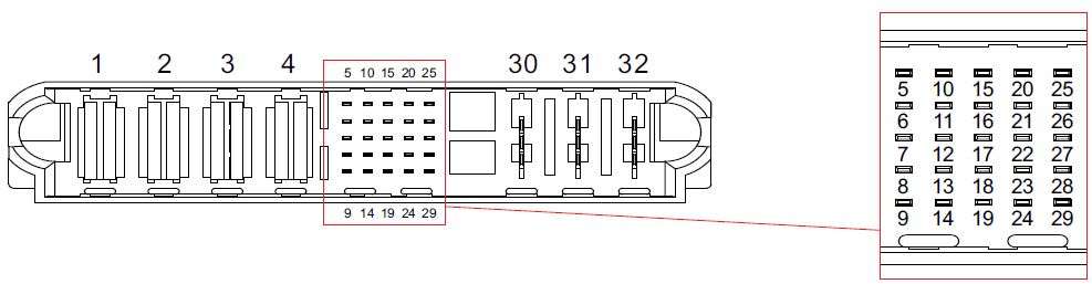
| Pin No. | Function | Description |
| 1,2 | -V | Negative output terminal. |
| 3,4 | +V | Positive output terminal. |
| 5 | +12V-AUX | Auxiliary voltage output, 10.8~13.2V, referenced to GND-AUX (pin 7).
The maximum load current is 0.8A. This output has the built-in “Oring diodes” and is not controlled by the Remote ON/OFF control. |
| 6 | +5V-AUX | Auxiliary voltage output,4.5~5.5V, reference to GND_AUX(pin7). The maximum load current is 0.3A. The output has the built-in “Oring diodes” and is not controlled by the Remote ON/OFF control. |
| 7 | GND-AUX | Auxiliary voltage output GND. The signal return is isolated from the output terminals (+V & -V). |
|
8 |
AC-OK |
High (3.5 ~ 5.5V): When the input voltage is ≧87Vrms. Low (-0.5 ~ 0.5V): When the input voltage is ≦75Vrms.
The maximum sourcing current is 10mA and only for output. (Note.2) |
|
9 |
T-ALARM |
High (3.5 ~ 5.5V): When the internal temperature exceeds the limit of the temperature alarm, or when the fan fails. Low (-0.5 ~ 0.5V): When the internal temperature is normal, and when the fan normally works.
The maximum sourcing current is 10mA and only for output(Note.2) |
| 10,24 | NC | Standard model: Retain for future use |
|
11 |
SCL | For PMBus model: Serial Clock used in the PMBus interface. (Note.2) |
| CANCEL | For CANBus model: Data line used in CANBus interface. (Note.2) | |
|
12 |
SDA | For PMBus model: Serial Data used in the PMBus interface. (Note.2) |
| CANH | For CANBus model: Data line used in CANBus interface. (Note.2) | |
| 13 | Remote ON-OFF | The unit can turn the output ON/OFF by electrical signal or dry contact between Remote ON/OFF and +5V-AUX. (Note.2) Short (4.5 ~ 5.5V) : Power ON ; Open (-0.5 ~ 0.5V) : Power OFF ; The maximum input voltage is 5.5V. |
|
14 |
DC-OK |
For power supply mode
High (3.5 ~ 5.5V): When the Vout ≦77%±5%. Low (-0.5 ~ 0.5V): When the Vout ≧80%±5%. The maximum sourcing current is 10mA and only for output. (Note.2) |
| For charger mode
High (3.5 ~ 5.5V): When the Vout ≦66%±5%. Low (-0.5 ~ 0.5V): When the Vout ≧67%±5%. The maximum sourcing current is 10mA and only for output. (Note.2) DC OK is associated with battery low protection. |
||
| 15,16 | DA, DB | Differential digital signal for parallel control. (Note.1) |
| 17 | PC | Connection for constant current-level programming. (Note.1) |
| 18,19,20,21 | A2,A3,A4,A5 | PMBus / CANBus interface address lines(for Rack system). (Note.1) |
| 22,23 | A0,A1 | PMBus / CANBus interface address lines for Rack-mountable front-end rectifier. (Note.1) |
| 25 | PV | Connection for output voltage programming. (Note.1) |
| 26 | -V (Signal) | Negative output voltage signal.
It is for local sense, and certain function references; it cannot be connected directly to the load. |
|
27 |
-S | Negative sensing for remote sense.(For 24V/48V models under power supply mode only) |
| NC | Not available for NCP-3200-380 | |
|
28 |
+S | Positive sensing for remote sensing. (For 24V/48V models under power supply mode only) |
| NC | Not available for NCP-3200-380 | |
|
29 |
+V (Signal) | Positive output voltage signal. (For 24V/48V models under power supply mode only)
It is for local sense; it cannot be connected directly to the load. |
| NC | Not available for NCP-3200-380 | |
| 30 | FG | AC Ground connection. |
| 32 | AC/L | AC Line connection. |
| 31 | AC/N | AC Neutral connection. |
Note 1: Non-isolated signal, referenced to [-V(signal)].
Note 2: Isolated signal, referenced to GND-AUX.
https://www.meanwell.com/serviceGTIN.aspx.