Contents
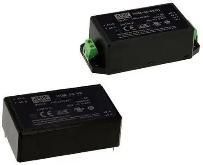
MEAN WELL IRM-45 AC DC PCB Mount Green Power Module
Product Information
- Product Name: 45W AC-DC PCB-Mount Green Power Module
- Series: IRM-45
- User’s Manual: Included (IRM-45)
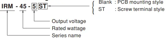
- Model Variants: IRM-45-xxST
- Certifications: LPS, UL62368-1, BS EN/EN62368-1, BS
EN/EN60335-1, R33100 RoHS, TPTC004, IEC62368-1
Product Features
- Bauart gepruft Sicherheit
- Compact size: 3.43”x2.05”
- Mounting Options: PCB, chassis or screw terminal
- Universal input: 85~305VAC
- No load power consumption (except for 5V)
Product Usage Instructions
- Ensure the input voltage is within the range of 85~305VAC.
- Choose the appropriate mounting option: PCB, chassis, or screw terminal.
- Connect the power module to the power source using the provided connectors.
- Make sure the no load power consumption is suitable for your application (except for 5V).
- Refer to the user’s manual (IRM-45) for detailed instructions on how to use and operate the product.
Features
- 3.43″×2.05″compact size
- PCB,chassis or screw terminal mounting version
- Universal input 85~305VAC
- No load power consumption 0.15W
EMI Class B without additional components - Wide operating temp. range -30~70°C
- Protections: Short circuit / Overload / Over voltage
- Cooling by free air convection
- Isolation Class II
- Over voltage category III
- Pass LPS(Except for 5V)
- 3 years warranty
Applications
- Industrial electrical equipment
- Mechanical equipment
- Factory automation equipment
- Handheld electronic device
GTIN CODE
MW Search: https://www.meanwell.com/serviceGTIN.aspx
Description
IRM-45 is a 45W miniature (87*52*29.5mm) AC-DC module-type power supply, ready to be soldered onto the PCB boards of various kinds of electronic instruments or industrial automation equipments. This product allows the universal input voltage range of 85~305VAC. The 94V-0 flame retardant plastic case and potted with silicone enhance the heat dissipation. PCB mounting style model(Blank) meet the anti-vibration demand up to 2G and screw terminal style model (ST) meet the anti-vibration demand up to 5G; moreover, it provides the fundamental resistance to dust and moisture. With the high efficiency up to 90.5% and the extremely low no-load power consumption below 0.15W, IRM-45 series fulfills the worldwide regulation for the low power consumption requirement for electronics. The entire series is a Class II design (no F pin), incorporating the built-in EMI filtering components, enabling the compliance with BS EN/EN55032 Class B; the supreme MC features keep the end electronic units from electromagnetic interference. In addition to the CB mounting style model, IRM-45 series also offers the screw terminal style model (ST).
Model Encoding
SPECIFICATION
| MODEL | IRM-45-5 | IRM-45-12 | IRM-45-15 | IRM-45-24 | IRM-45-48 | |||
|
OUTPUT |
DC VOLTAGE | 5V | 12V | 15V | 24V | 48V | ||
| RATED CURRENT | 8A | 3.8A | 3A | 1.9A | 0.94A | |||
| CURRENT RANGE | 0 ~ 8A | 0 ~ 3.8A | 0 ~ 3A | 0 ~ 1.9A | 0 ~ 0.94A | |||
| RATED POWER | 40W | 45.6W | 45W | 45.6W | 45.12W | |||
| RIPPLE & NOISE (max.) Note.2 | 80mVp-p | 150mVp-p | 180mVp-p | 200mVp-p | 300mVp-p | |||
| VOLTAGE TOLERANCE Note.3 | ±2.5% | ±2.5% | ±2.5% | ±2.5% | ±2.5% | |||
| LINE REGULATION | ±0.5% | ±0.5% | ±0.5% | ±0.5% | ±0.5% | |||
| LOAD REGULATION | ±1.0% | ±1.0% | ±0.5% | ±0.5% | ±0.5% | |||
| SETUP, RISE TIME | 1000ms, 30ms/230VAC 2000ms, 30ms/115VAC at full load | |||||||
| HOLD UP TIME (Typ.) | 50ms/230VAC 12ms/115VAC at full load | |||||||
|
INPUT |
VOLTAGE RANGE | 85 ~ 305VAC | ||||||
| FREQUENCY RANGE | 47 ~ 440Hz | |||||||
| EFFICIENCY (Typ.) | 83.5% | 87.5% | 88.5% | 89.5% | 90.5% | |||
| AC CURRENT (Typ.) | 1.5A/115VAC 0.9A/230VAC 0.75A/277VAC | |||||||
| INRUSH CURRENT (Typ.) | COLD START 30A/115VAC 60A/230VAC | |||||||
| LEAKAGE CURRENT | < 0.25mA/277VAC | |||||||
|
PROTECTION |
OVERLOAD |
115%~160% rated output power | ||||||
| Protection type : Hiccup mode, recovers automatically after fault condition is removed | ||||||||
|
OVER VOLTAGE |
5.25 ~ 6.75V | 12.6 ~ 16.2V | 15.75 ~ 20.25V | 25.2 ~ 32.4V | 50.4 ~ 64.8V | |||
| Protection type : Shut off o/p voltage, clamping by zener diode | ||||||||
|
ENVIRONMENT |
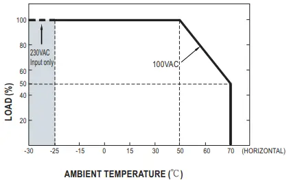
WORKING TEMP. | -30 ~ +70℃ (Refer to “Derating Curve”) | ||||||
| WORKING HUMIDITY | 20 ~ 90% RH non-condensing | |||||||
| STORAGE TEMP., HUMIDITY | -40 ~ +85℃, 10 ~ 95% RH | |||||||
| TEMP. COEFFICIENT | ±0.03%/℃ (0 ~ 50℃) | |||||||
|
VIBRATION |
Blank:10 ~ 500Hz, 2G 10min./1cycle, period for 60min. each along X, Y, Z axes | |||||||
| ST:10 ~ 500Hz, 5G 10min./1cycle, period for 60min. each along X, Y, Z axes | ||||||||
| SOLDERING TEMPERATURE | Wave soldering: 265℃,5s (max.); Manual soldering: 390℃,3s (max.) | |||||||
| OVER VOLTAGE CATEGORY | Ⅲ; According to EN62368-1;altitude up to 2000 meters | |||||||
| OPERATING ALTITUDE Note.4 | 2000 meters | |||||||
|
SAFETY & EMC (Note.5) |
SAFETY STANDARDS | IEC62368-1, UL62368-1, TUV BS EN/EN62368-1, BS EN/EN60335-1, EAC TP TC 004, BSMI CNS14336-1 approved | ||||||
| WITHSTAND VOLTAGE | I/P-O/P:4KVAC | |||||||
| ISOLATION RESISTANCE | I/P-O/P:100M Ohms / 500VDC / 25℃/ 70% RH | |||||||
|
EMC EMISSION |
Parameter | Standard | Test Level / Note | |||||
| Conducted | BS EN/EN55032(CISPR32), CNS13438 | Class B | ||||||
| Radiated | BS EN/EN55032(CISPR32), CNS13438 | Class B | ||||||
| Harmonic Current (Note 5) | BS EN/EN61000-3-2 | Class A | ||||||
| Voltage Flicker | BS EN/EN61000-3-3 | ——- | ||||||
|
EMC IMMUNITY |
BS EN/EN55035, BS EN/EN61000-6-2 | |||||||
| Parameter | Standard | Test Level /Note | ||||||
| ESD | BS EN/EN61000-4-2 | Level 3, 8KV air; Level 2, 4KV contact, criteria A | ||||||
| Radiated Susceptibility | BS EN/EN61000-4-3 | Level 3, criteria A | ||||||
| EFT/Burest | BS EN/EN61000-4-4 | Level 3, criteria A | ||||||
| Surge | BS EN/EN61000-4-5 | Level 4, 2KV/L-N, criteria A | ||||||
| Conducted | BS EN/EN61000-4-6 | Level 3, criteria A | ||||||
| Magnetic Field | BS EN/EN61000-4-8 | Level 4, criteria A | ||||||
| Voltage Dips and interruptions | BS EN/EN61000-4-11 | >95% dip 0.5 periods, 30% dip 25 periods,
>95% interruptions 250 periods |
||||||
|
OTHERS |
MTBF | 6451.1K hrs min. Telcordia SR-332 (Bellcore) ; 1212.1K hrs min. MIL-HDBK-217F (25℃) | ||||||
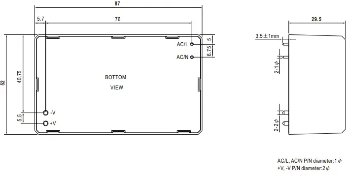
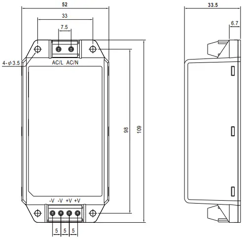
| DIMENSION | PCB mounting style : 87*52*29.5mm (L*W*H) Screw terminal style : 109*52*33.5mm (L*W*H) | |||||||
| PACKING | PCB mounting style : 0.195Kg;60pcs/12.7Kg/0.94CUFT Screw terminal style :0.228Kg; 50pcs/12.4Kg/0.56CUFT | |||||||
|
NOTE |
1. All parameters NOT specially mentioned are measured at 230VAC input, rated load and 25℃ of ambient temperature.
2. Ripple & noise are measured at 20MHz of bandwidth by using a 12″ twisted pair-wire terminated with a 0.1uf & 47uf parallel capacitor. 3. Tolerance : includes set up tolerance, line regulation and load regulation. 4. The ambient temperature derating of 3.5℃/1000m with fanless models and of 5℃/1000m with fan models for operating altitude higher than 2000m( 500ft). 5. The power supply is considered as an independent unit ,but the final equipment still need to re-confirm that the whole system complieswith the EMC directives. For guidance on how to perform these EMC tests, please refer to “EMI testing of component power supplies.” (as available on https://www.meanwell.com) ※ Product Liability Disclaimer:For detailed information, please refer to https://www.meanwell.com/serviceDisclaimer.aspx |
|||||||
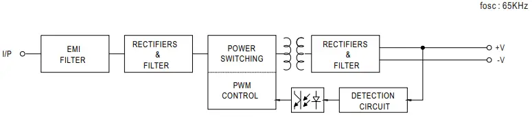
Block Diagram
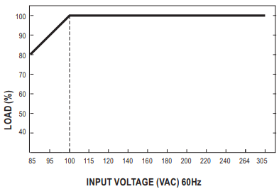
Derating Curve
Output Derating VS Input Voltage
Mechanical Specification
PCB mounting style (IRM-45)
Screw terminal style (IRM-45-xxST)
Installation Manual
Please refer to : https://www.meanwell.com/manual.html