Contents
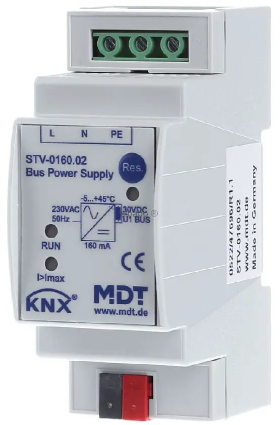
MDT STV-160.02 KNX B Bus Power Supply STV
Product Information
The MDT KNX Power Supply is a modular installation device designed for fixed installation in dry rooms. It is used to produce the stabilized KNX system voltage (30VDC) to supply the connected KNX components. The power supply comes in three variants:
STV-160.02, STV-320.02, and STV-640.02.
The power supply operates at a mains voltage of 230VAC/50Hz and has an output voltage of 30VDC SELV (Safety Extra Low Voltage). The choke-free output voltage is available only in the STV-640.02 variant. The nominal current ranges from 160mA to 640mA, with continuous and peak current values specified for each variant. The power supply has an efficiency of over 82% at nominal load and apower loss of less than 0.45W in no operation mode.
The power supply has a compact design with dimensions of 2TE or 4TE, depending on the variant. It has an IP 20 enclosure rating, indicating protection against solid objects greater than 12mm andno protection against water ingress. The permitted wire gauge for
connection is not specified.
Product Usage Instructions
- Installation and Commissioning:
- Installation and commissioning of the power supply should only be carried out by authorized electricians.
- Ensure compliance with relevant standards, directives, regulations, and instructions.
- The power supply is approved for use in the EU and bears the CE mark. Its use in the USA and Canada is prohibited.
- Mount the power supply on DIN 35mm rails in power distribution boards or closed compact boxes.
- Connection:
- Connect the mains power supply to the power supply.
- Ensure the power supply is properly connected before operation.
- Indication LEDs:
- The power supply has three indication LEDs:
- Red LED: Indicates a reset of the KNX Bus.
- Green LED: Indicates normal operation with no faults.
- Yellow LED: Indicates a KNX bus overload.
- The power supply has three indication LEDs:
Operating Instructions
Operating Instructions Power Supply STV – for authorised electricans
Important safety notes
Danger High Voltage
- Installation and commissioning of the device only be carried out by authorised electricans. The relevant standards, directives, regulations and instructions must be observed. The devices are approved for use in the EU and have the CE mark. Use in USA and Canada is prohibited.
- After Installation and connecting mains power supply the outputs are aliv
- Disconnect the mains power supply prior to installation or disassembly
- All screw terminals and connections under current must be covered completely against touching by the switch panel.
It should not be possible to open the switch panel cover without using tools.
Terminals and Display Power Supply STV
STV-160.02 / STV-320.02
STV-640.02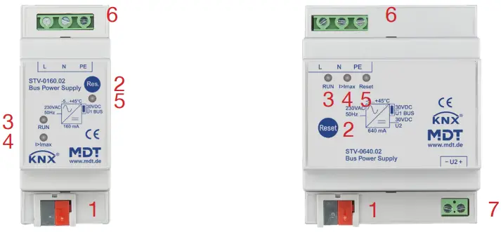
- KNX busconnection terminal
- Reset key
- Green LED: Normal operation
- Yellow LED: KNX Bus overload
- Red LED: Reset
- mains power supply terminal
- choke free output
Technical Data Power Supply
|
Technical Data |
STV-160.02 | STV-320.02 | STV-640.02 |
| Spannung Voltage | |||
| Mains voltage |
230VAC/50Hz |
230VAC/50Hz |
230VAC/50Hz |
| Output voltage | 30VDC SELV | 30VDC SELV | 30VDC SELV |
| Choke free output voltage | — | — | 30VDC SELV |
| Strom Current | |||
| Nominal current |
160mA |
320mA |
640mA |
| Continuous current | 240mA | 480mA | 960mA |
| Peak current | 320mA | 640mA | 1200mA |
| Max. total current of both outputs | — | — | 1000mA |
|
Efficiency at nominal load typ.* |
> 82% | > 85% |
> 87% |
| Power loss no operation typ. | < 0,45W | < 0,45W | < 0,75W |
| Overvoltage catagory | III | III | III |
| Permitted wire gauge | |||
| Screw terminal (max. 0,5Nm tightening torque) | 0,5 – 4,0mm² solid core
0,5 – 2,5mm² finely stranded |
0,5 – 4,0mm² solid core
0,5 – 2,5mm² finely stranded |
0,5 – 4,0mm² solid core
0,5 – 2,5mm² finely stranded |
|
KNX busconnection terminal |
0,8mm Ø, solid core | 0,8mm Ø, solid core | 0,8mm Ø, solid core |
| Operation temperature range | 0 bis + 45°C | 0 bis + 45°C | 0 bis + 45°C |
| Enclosure | IP 20 | IP 20 | IP 20 |
| Dimensions MDRC (Space Units) | 2TE | 2TE | 4TE |
Efficiency before choke
Installation Power Supply STV
- Place the Power Supply on DIN 35mm rail.
- Connect the Power Supply to the KNX bus.
- Wire up the Power Supply as descripted in the circuit diagram.
- Switch up mains power supply.
Exemplary circuit diagram STV-160.02/ STV-320.02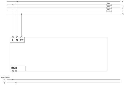
Exemplary circuit diagram STV-640.02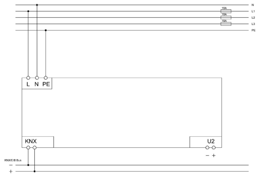
Description Power Supply STV
The MDT KNX Power Supply with integrated choke produces the stabilized KNX system voltage (30VDC) to supply the connected KNX components. Once the fault has been rectified, the Power Supply restarts itself. Additionally the Power Supply STV-640.02 offers a choke free output. The Power Supply is a modular installation device for fixed installation in dry rooms. It fits on DIN 35mm rails in power distribution boards or closed compact boxes.
Commisionning Power Supply STV
The Power supply is ready for operation after connection of the mains power supply.
Indication LED Power Supply STV
- Red LED: Reset of the KNX Bus
- Green LED: Normal operation, no faults
- Yellow LED: KNX bus overload
MDT technologies GmbH
- 51766 Engelskirchen
- Papiermühle 1
- Tel.: + 49 – 2263 – 880
- Fax: + 49 – 2263 – 4588
- [email protected]
- www.mdt.de