Contents
MAYTAG PGC2TE Series 96 Percent AFUE Two Stage Fixed Speed High Efficiency Gas Furnace
Product Information
The high-efficiency gas furnace may be installed free-standing in a utility room, basement, or enclosed in an alcove or closet. The rounded corner jacket provides a pleasing appliance appearance. Design certified by CSA for application in Canada and the United States.
Technical Specifications
- Model: PGC2TE Series
- M1200 Product Line
- Type: Two Stage, Fixed Speed ECM, High-Efficiency Upflow Gas Furnaces
- AFUE: 96%
- Input: 60,000-115,000 Btuh
Features and Benefits
- Multi-Speed Direct Drive Blower: Energy-efficient brushless DC
- GAS FURNACE COMPONENTS
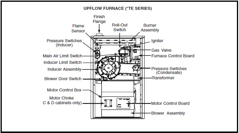
- UPFLOW FURNACE (*TE SERIES)
Air Flow
- Flame Sensor
- Finish Flange
- Roll-Out Switch
- Burner Assembly
- Pressure Switches (Inducer)
- Main Air Limit Switch Inducer Limit Switch
- Inducer Assembly
- Blower Door Switch
- Igniter
- Gas Valve Furnace Control Board
- Pressure Switches (Condensate)
- Transformer
- Motor Control Box
- Motor Choke (C & D cabinets only)
- Motor Control Board Blower Assembly
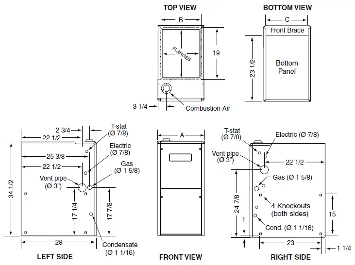
Dimensions
TE Model #s: 035DEA1, 060DEB1, 080DEC1, 100DEC1, 115DED1
| Dimension A | Dimension B | Dimension C | |
|---|---|---|---|
| Top View B | 14 1/4 | 12 5/8 | 12 7/8 |
| Bottom View C | 17 1/2 | 15 7/8 | 16 1/8 |
| Front View | 19 3/8 | 19 5/8 | 24 1/2 |
| Left Side | 22 7/8 | 23 1/8 | 24 7/8 |
| Right Side | 23 1/2 | 34 1/2 | 17 1/4 |
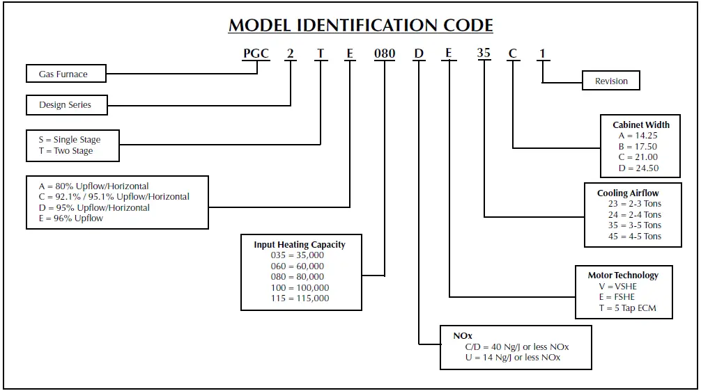
Identification Code
- Gas Furnace Design Series: S = Single Stage, T = Two Stage, A = 80% Upflow/Horizontal, C = 92.1% / 95.1% Upflow/Horizontal, D = 95% Upflow/Horizontal, E = 96% Upflow
- Model Identification Code: PGC2TE080DE35C1
- Revision:
- Input Heating Capacity: 080 = 80,000
- Cabinet Width: C = 21.00
- Cooling Airflow: 35 = 3-5 Tons
- Motor Technology: E = FSHE
- NOx: C/D = 40 Ng/J or less NOx
Specifications
| PGC2TE MODEL NUMBERS | Input – Btuh (a) | Heating Capacity – BtuH | AFUE | Motor H.P. – Speed – Type | Motor FLA | Rated Ext. SP – In. W.C. | Temperature Rise Range – F | Shipping Weights SKU |
|---|---|---|---|---|---|---|---|---|
| 035DE23A1 | 35000 / 23000 | 33000 / 22000 | 96.0 | 1/2 – BLDC | 6.9 | 0.50 | 30-60 | 101 lb |
| 060DE24B1 | 60000 / 39000 | 58000 / 37000 | 96.0 | 3/4 – BLDC | 8.8 | 0.50 | 30-60 | 120 lb |
| 080DE35C1 | 80000 / 52000 | 77000 / 50000 | 96.0 | 1 – BLDC | 11.5 | 0.50 | 30-60 | 130 lb |
| 100DE35C1 | 100000 / 65000 | 96000 / 62000 | 96.0 | 1 – BLDC | 11.5 | 0.50 | 35-65 | 135 lb |
| 115DE45D1 | 115000 / 74750 | 110000 / 72000 | 96.0 | 1 – BLDC | 11.5 | 0.50 | 40-70 | 145 lb |
Note:
All models are 115V, 60 Hz. Gas Connections are 1/2 N.P.T. AFUE = Annual Fuel Utilization Efficiency (a) Ratings to 2,000 ft. Over 2,000 ft. reduce 4% for each 1,000 ft. above sea level.
Blower Performance
| Model Number/ Heating Input | MOTOR SWITCH SETTINGS (0=OFF, 1=ON) |
|---|---|
| PGC2TE-035D-E23A1 | 1 1 1 0 0000 1000 0100 1100 0010 1010 0110 0001 1001 0101 1101 0011 1011 0111 1111 |
FAQ
- Q: What is the AFUE of the gas furnace?
A: The AFUE of the gas furnace is 96%. - Q: What is the input heating capacity range of the gas furnace?
A: The input heating capacity range of the gas furnace is 60,000-115,000 Btuh. - Q: What are the dimensions of the gas furnace?
A: The dimensions vary depending on the model. Please refer to the table in the “Dimensions” section for specific dimensions. - Q: What is the motor technology used in the gas furnace?
A: The motor technology used in the gas furnace is FSHE (Fixed Speed ECM).
The high-efficiency gas furnace may be installed free-standing in a utility room, basement, or enclosed in an alcove or closet. The rounded corner jacket provides a pleasing “appliance appearance.” Design certified by CSA for application in Canada and the United States.
Features and Benefits
- Multi-Speed Direct Drive Blower: Energy-efficient brushless DC (ECM) fixed-speed motor offers 16 speeds designed to give a wide range of cooling capacities.
- Two-Stage Inducer: Optimizes efficiency on first-stage heat and reduces sound levels.
- 100% Fired and Tested: All units and each component are tested on the manufacturing line.
- Best Packaging in the Industry: Unique corner post design assures the product will arrive to the homeowner dent-free.
- 30 Second Blower Delay: At start-up assures a warm duct temperature at furnace start-up. Adjustable blower-off settings (60, 90, 120 and 180 seconds).
- 30-Second Post Purge: Increases the life of the heat exchanger.
- Hot Surface Igniter: Innovative application of an appliance-type igniter with a 20-year history of reliability. Utilizes proven SmartStart® technology.
- Color Coded Wire Harness: Designed to fit the components, all with quick-connect fittings for ease of service and replacement.
- Flexible Category IV Venting System: May be vertically or horizontally vented using either a one-pipe or two-pipe system for maximum installation flexibility.
- High Static Blowers: All models are equipped with high static ECM blowers.
- Low Boy Height: Easy to apply in low ceiling applications, works well with taller high SEER coils, easier to handle and install.
- Heat Exchanger: Heavy gauge aluminized steel primary heat exchanger and stainless steel secondary heat exchanger ensure a long life.
- 60 Second Fixed Cooling Cycle Blower-Off Delay (TDR): Increases cooling performance when matched with a Nortek Global HVAC evaporator coil.
- LP Convertible: Simple burner orifice and regulator spring change for ease of convertibility (as an accessory).
- Diagnostic Lights: Dedicated light for flame signal strength and 2 lights in combination to indicate all other fault codes with easy to recognize states without counting flashes.
- Integrated Control Boards: With connections for electronic air cleaners, humidifiers, and dehumidification. Ergonomically located for ease of service.
- Two-Piece Door Design: Enhances furnace appearance and uses captured screws to prevent losing door screws.
- Blower Compartment: Sealed door to reduce air leakage and insulated for ultra-quiet operation.
- Sealed Vestibule: Reduces burner and inducer sound levels.
- Furnace Air Leakage: These furnaces comply with Energy Star cabinet air leakage requirement of less than or equal to 2%. Keep the conditioned air flowing to where it’s needed.
GAS FURNACE COMPONENTS
DIMENSIONS
| *TE Model #s | Dimension “A” | Dimension “B” | Dimension “C” |
| 035DEA1 | 14 1/4 | 12 5/8 | 12 7/8 |
| 060DEB1 | 17 1/2 | 15 7/8 | 16 1/8 |
| 080DEC1 | 21 | 19 3/8 | 19 5/8 |
| 100DEC1 | |||
| 115DED1 | 24 1/2 | 22 7/8 | 23 1/8 |
IDENTIFICATION CODE
SPECIFICATIONS
| PGC2TE MODEL NUMBERS: | 035DE23A1 | 060DE24B1 | 080DE35C1 | 100DE35C1 | 115DE45D1 |
| Input – Btuh (a) | 35000 / 23000 | 60000 / 39000 | 80000 / 52000 | 100000 / 65000 | 115000 / 74750 |
| Heating Capacity – BtuH | 33000 / 22000 | 58000 / 37000 | 77000 / 50000 | 96000 / 62000 | 110000 / 72000 |
| AFUE | 96.0 | 96.0 | 96.0 | 96.0 | 96.0 |
| Motor H.P. – Speed – Type | 1/2 – BLDC | 3/4 – BLDC | 1 – BLDC | 1 – BLDC | 1 – BLDC |
| Motor FLA | 6.9 | 8.8 | 11.5 | 11.5 | 11.5 |
| Rated Ext. SP – In. W.C. | 0.50 | 0.50 | 0.50 | 0.50 | 0.50 |
| Temperature Rise Range – F | 30-60 | 30-60 | 30-60 | 35-65 | 40-70 |
| Shipping Weights | 101 lb | 120 lb | 130 lb | 135 lb | 145 lb |
| SKU | 1037159P | 1025958P | 1025959P | 1025960P | 1025961P |
Note:
All models are 115V, 60 Hz. Gas Connections are 1/2″ N.P.T. AFUE = Annual Fuel Utilization Efficiency (a) Ratings to 2,000 ft. Over 2,000 ft. reduce 4% for each 1,000 ft. above sea level.
BLOWER PERFORMANCE
| HEATING AIRFLOW (CFM) & TEMPERATURE RISE (°F) | ||||||||||||||
|
Model Number/ Heating Input |
MOTOR SWITCH SETTINGS (0=OFF, 1=ON) | External Static Pressure (in.w.c.) | ||||||||||||
| 0.1 | 0.2 | 0.3 | 0.4 | 0.5 | ||||||||||
| 1 | 2 | 3 | 4 | CFM | RISE | CFM | RISE | CFM | RISE | CFM | RISE | CFM | RISE | |
|
PGC2TE-035D-E23A1 35,000 BTU/hr |
0 | 0 | 0 | 0 | ||||||||||
| 1 | 0 | 0 | 0 | 560 | 56 | 515 | 60 | |||||||
| 0 | 1 | 0 | 0 | 570 | 55 | 540 | 58 | |||||||
| 1 | 1 | 0 | 0 | 670 | 46 | 635 | 49 | 595 | 52 | 565 | 55 | 525 | 59 | |
| 0 | 0 | 1 | 0 | 700 | 44 | 670 | 46 | 635 | 49 | 600 | 52 | 565 | 55 | |
| 1 | 0 | 1 | 0 | 765 | 41 | 725 | 43 | 690 | 45 | 660 | 47 | 625 | 50 | |
| 0 | 1 | 1 | 0 | 795 | 39 | 755 | 41 | 720 | 43 | 690 | 45 | 650 | 48 | |
| 1 | 1 | 1 | 0 | 845 | 37 | 810 | 38 | 775 | 40 | 740 | 42 | 705 | 44 | |
| 0 | 0 | 0 | 1 | 895 | 35 | 860 | 36 | 825 | 38 | 790 | 39 | 760 | 41 | |
| 1 | 0 | 0 | 1 | 905 | 34 | 870 | 36 | 840 | 37 | 805 | 39 | 770 | 40 | |
| 0 | 1 | 0 | 1 | 950 | 33 | 920 | 34 | 885 | 35 | 850 | 37 | 820 | 38 | |
| 1 | 1 | 0 | 1 | 990 | 31 | 955 | 33 | 925 | 34 | 890 | 35 | 860 | 36 | |
| 0 | 0 | 1 | 1 | 1010 | 31 | 980 | 32 | 945 | 33 | 910 | 34 | 885 | 35 | |
| 1 | 0 | 1 | 1 | 1050 | 30 | 1015 | 31 | 985 | 32 | 955 | 33 | 925 | 34 | |
| 0 | 1 | 1 | 1 | 1045 | 30 | 1020 | 31 | 990 | 31 | 960 | 32 | |||
| 1 | 1 | 1 | 1 | |||||||||||
| COOLING AIRFLOW (CFM) | ||||||||||||
|
Model Number/ Heating Input |
MOTOR SWITCH SETTINGS (0=OFF, 1=ON) | External Static Pressure (in.w.c.) | ||||||||||
| 0.1 | 0.2 | 0.3 | 0.4 | 0.5 | 0.6 | 0.7 | 0.8 | |||||
| 5 | 6 | 7 | 8 | CFM | CFM | CFM | CFM | CFM | CFM | CFM | CFM | |
|
PGC2TE-035D-E23A1 35,000 BTU/hr |
0 | 0 | 0 | 0 | ||||||||
| 1 | 0 | 0 | 0 | 560 | 515 | 475 | ||||||
| 0 | 1 | 0 | 0 | 570 | 540 | 505 | 460 | |||||
| 1 | 1 | 0 | 0 | 670 | 635 | 595 | 565 | 525 | 485 | |||
| 0 | 0 | 1 | 0 | 700 | 670 | 635 | 600 | 565 | 530 | 485 | ||
| 1 | 0 | 1 | 0 | 765 | 725 | 690 | 660 | 625 | 585 | 550 | 510 | |
| 0 | 1 | 1 | 0 | 795 | 755 | 720 | 690 | 650 | 615 | 580 | 545 | |
| 1 | 1 | 1 | 0 | 845 | 810 | 775 | 740 | 705 | 675 | 640 | 600 | |
| 0 | 0 | 0 | 1 | 895 | 860 | 825 | 790 | 760 | 725 | 695 | 660 | |
| 1 | 0 | 0 | 1 | 905 | 870 | 840 | 805 | 770 | 740 | 700 | 670 | |
| 0 | 1 | 0 | 1 | 950 | 920 | 885 | 850 | 820 | 785 | 760 | 720 | |
| 1 | 1 | 0 | 1 | 990 | 955 | 925 | 890 | 860 | 830 | 800 | 765 | |
| 0 | 0 | 1 | 1 | 1010 | 980 | 945 | 910 | 885 | 850 | 820 | 790 | |
| 1 | 0 | 1 | 1 | 1050 | 1015 | 985 | 955 | 925 | 895 | 865 | 830 | |
| 0 | 1 | 1 | 1 | 1080 | 1045 | 1020 | 990 | 960 | 930 | 895 | 865 | |
| 1 | 1 | 1 | 1 | 1105 | 1075 | 1045 | 1015 | 985 | 955 | 920 | 895 | |
NOTES:
- For motor switch settings for heating speeds use HEAT switches 1, 2, 3, & 4 and for cooling speeds use COOL switches 5, 6, 7, & 8.
- To comply with government-mandated efficiency standards, two openings are required for airflows above 1,600 CFM.
- Data is shown without the filter.
- Temperature rises in the table are approximate. Actual temperature rises may vary.
- Individual cells shaded in gray indicate a temperature rise outside of the recommended range.
- To comply with government-mandated efficiency standards, speed settings shaded in gray are not allowed in HEAT mode.
- When in low-stage heat, the airflow is approximately 70% of the table’s high value (2-stage furnaces only).
| HEATING AIRFLOW (CFM) & TEMPERATURE RISE (°F) | ||||||||||||||
|
Model Number/ Heating Input |
MOTOR SWITCH SETTINGS (0=OFF, 1=ON) | External Static Pressure (in.w.c.) | ||||||||||||
| 0.1 | 0.2 | 0.3 | 0.4 | 0.5 | ||||||||||
| 1 | 2 | 3 | 4 | CFM | RISE | CFM | RISE | CFM | RISE | CFM | RISE | CFM | RISE | |
|
PGC2TE-060D-E24B1 60,000 BTU/hr |
0 | 0 | 0 | 0 | ||||||||||
| 1 | 0 | 0 | 0 | |||||||||||
| 0 | 1 | 0 | 0 | |||||||||||
| 1 | 1 | 0 | 0 | |||||||||||
| 0 | 0 | 1 | 0 | |||||||||||
| 1 | 0 | 1 | 0 | 940 | 57 | 890 | 60 | |||||||
| 0 | 1 | 1 | 0 | 990 | 54 | 945 | 56 | 905 | 59 | |||||
| 1 | 1 | 1 | 0 | 1,055 | 51 | 1,015 | 53 | 970 | 55 | 930 | 57 | 890 | 60 | |
| 0 | 0 | 0 | 1 | 1,135 | 47 | 1,095 | 49 | 1,055 | 51 | 1,010 | 53 | 960 | 56 | |
| 1 | 0 | 0 | 1 | 1,185 | 45 | 1,145 | 47 | 1,105 | 48 | 1,065 | 50 | 1,030 | 52 | |
| 0 | 1 | 0 | 1 | 1,250 | 43 | 1,210 | 44 | 1,170 | 46 | 1,135 | 47 | 1,095 | 49 | |
| 1 | 1 | 0 | 1 | 1,290 | 41 | 1,255 | 42 | 1,220 | 44 | 1,180 | 45 | 1,145 | 47 | |
| 0 | 0 | 1 | 1 | 1,315 | 41 | 1,275 | 42 | 1,240 | 43 | 1,200 | 44 | 1,160 | 46 | |
| 1 | 0 | 1 | 1 | 1,350 | 40 | 1,315 | 41 | 1,280 | 42 | 1,245 | 43 | 1,205 | 44 | |
| 0 | 1 | 1 | 1 | 1,390 | 38 | 1,350 | 40 | 1,315 | 41 | 1,275 | 42 | 1,240 | 43 | |
| 1 | 1 | 1 | 1 | |||||||||||
| COOLING AIRFLOW (CFM) | ||||||||||||
|
Model Number/ Heating Input |
MOTOR SWITCH SETTINGS (0=OFF, 1=ON) | External Static Pressure (in.w.c.) | ||||||||||
| 0.1 | 0.2 | 0.3 | 0.4 | 0.5 | 0.6 | 0.7 | 0.8 | |||||
| 5 | 6 | 7 | 8 | CFM | CFM | CFM | CFM | CFM | CFM | CFM | CFM | |
|
PGC2TE-060D-E24B1 60,000 BTU/hr |
0 | 0 | 0 | 0 | ||||||||
| 1 | 0 | 0 | 0 | |||||||||
| 0 | 1 | 0 | 0 | |||||||||
| 1 | 1 | 0 | 0 | 725 | ||||||||
| 0 | 0 | 1 | 0 | 810 | ||||||||
| 1 | 0 | 1 | 0 | 940 | 890 | 845 | 795 | 750 | 700 | |||
| 0 | 1 | 1 | 0 | 990 | 945 | 905 | 860 | 820 | 775 | 735 | 690 | |
| 1 | 1 | 1 | 0 | 1,055 | 1,015 | 970 | 930 | 890 | 845 | 805 | 760 | |
| 0 | 0 | 0 | 1 | 1,135 | 1,095 | 1,055 | 1,010 | 960 | 930 | 890 | 850 | |
| 1 | 0 | 0 | 1 | 1,185 | 1,145 | 1,105 | 1,065 | 1,030 | 990 | 950 | 910 | |
| 0 | 1 | 0 | 1 | 1,250 | 1,210 | 1,170 | 1,135 | 1,095 | 1,055 | 1,020 | 980 | |
| 1 | 1 | 0 | 1 | 1,290 | 1,255 | 1,220 | 1,180 | 1,145 | 1,110 | 1,075 | 1,040 | |
| 0 | 0 | 1 | 1 | 1,315 | 1,275 | 1,240 | 1,200 | 1,160 | 1,120 | 1,085 | 1,045 | |
| 1 | 0 | 1 | 1 | 1,350 | 1,315 | 1,280 | 1,245 | 1,205 | 1,170 | 1,135 | 1,100 | |
| 0 | 1 | 1 | 1 | 1,390 | 1,350 | 1,315 | 1,275 | 1,240 | 1,200 | 1,160 | 1,125 | |
| 1 | 1 | 1 | 1 | 1,420 | 1,380 | 1,345 | 1,310 | 1,270 | 1,235 | 1,200 | 1,160 | |
NOTES:
- For motor switch settings for heating speeds use HEAT switches 1, 2, 3, & 4 and for cooling speeds use COOL switches 5, 6, 7, & 8.
- To comply with government-mandated efficiency standards, two openings are required for airflows above 1,600 CFM.
- Data is shown without a filter.
- Temperature rises in the table are approximate. Actual temperature rises may vary.
- Individual cells shaded in gray indicate a temperature rise outside of the recommended range.
- To comply with government-mandated efficiency standards, speed settings shaded in gray are not allowed in HEAT mode.
- When in low-stage heat, the airflow is approximately 70% of the table’s high value (2-stage furnaces only).
| HEATING AIRFLOW (CFM) & TEMPERATURE RISE (°F) | ||||||||||||||
|
Model Number/ Heating Input |
MOTOR SWITCH SETTINGS (0=OFF, 1=ON) | External Static Pressure (in.w.c.) | ||||||||||||
| 0.1 | 0.2 | 0.3 | 0.4 | 0.5 | ||||||||||
| 1 | 2 | 3 | 4 | CFM | RISE | CFM | RISE | CFM | RISE | CFM | RISE | CFM | RISE | |
|
PGC2TE-080D-E35C1 80,000 BTU/hr |
0 | 0 | 0 | 0 | 1,125 | 63 | ||||||||
| 1 | 0 | 0 | 0 | 1,205 | 59 | 1,120 | 63 | |||||||
| 0 | 1 | 0 | 0 | 1,305 | 54 | 1,225 | 58 | 1,150 | 62 | |||||
| 1 | 1 | 0 | 0 | 1,430 | 50 | 1,350 | 53 | 1,270 | 56 | 1,190 | 60 | 1,110 | 63 | |
| 0 | 0 | 1 | 0 | 1,525 | 47 | 1,450 | 49 | 1,375 | 52 | 1,300 | 55 | 1,225 | 57 | |
| 1 | 0 | 1 | 0 | 1,620 | 44 | 1,540 | 46 | 1,465 | 49 | 1,390 | 51 | 1,315 | 54 | |
| 0 | 1 | 1 | 0 | 1,695 | 42 | 1,620 | 44 | 1,545 | 46 | 1,465 | 49 | 1,390 | 51 | |
| 1 | 1 | 1 | 0 | 1,770 | 40 | 1,700 | 42 | 1,630 | 44 | 1,555 | 46 | 1,485 | 47 | |
| 0 | 0 | 0 | 1 | 1,875 | 38 | 1,805 | 39 | 1,730 | 41 | 1,655 | 43 | 1,580 | 45 | |
| 1 | 0 | 0 | 1 | 1,905 | 37 | 1,840 | 39 | 1,775 | 40 | 1,710 | 42 | 1,640 | 43 | |
| 0 | 1 | 0 | 1 | 1,980 | 36 | 1,910 | 37 | 1,845 | 39 | 1,780 | 40 | 1,715 | 41 | |
| 1 | 1 | 0 | 1 | 2,025 | 35 | 1,960 | 36 | 1,895 | 38 | 1,830 | 39 | 1,765 | 40 | |
| 0 | 0 | 1 | 1 | 2,025 | 35 | 1,960 | 36 | 1,900 | 37 | 1,840 | 38 | |||
| 1 | 0 | 1 | 1 | 2,010 | 35 | 1,945 | 37 | 1,880 | 37 | |||||
| 0 | 1 | 1 | 1 | 2,035 | 35 | 1,980 | 36 | |||||||
| 1 | 1 | 1 | 1 | |||||||||||
| COOLING AIRFLOW (CFM) | ||||||||||||
|
Model Number/ Heating Input |
MOTOR SWITCH SETTINGS (0=OFF, 1=ON) | External Static Pressure (in.w.c.) | ||||||||||
| 0.1 | 0.2 | 0.3 | 0.4 | 0.5 | 0.6 | 0.7 | 0.8 | |||||
| 5 | 6 | 7 | 8 | CFM | CFM | CFM | CFM | CFM | CFM | CFM | CFM | |
|
PGC2TE-080D-E35C1 80,000 BTU/hr |
0 | 0 | 0 | 0 | 1,125 | 1,040 | 960 | 880 | 795 | |||
| 1 | 0 | 0 | 0 | 1,205 | 1,120 | 1,040 | 960 | 875 | 795 | |||
| 0 | 1 | 0 | 0 | 1,305 | 1,225 | 1,150 | 1,070 | 995 | 915 | 840 | ||
| 1 | 1 | 0 | 0 | 1,430 | 1,350 | 1,270 | 1,190 | 1,110 | 1,030 | 950 | 865 | |
| 0 | 0 | 1 | 0 | 1,525 | 1,450 | 1,375 | 1,300 | 1,225 | 1,150 | 1,075 | 1,000 | |
| 1 | 0 | 1 | 0 | 1,620 | 1,540 | 1,465 | 1,390 | 1,315 | 1,240 | 1,165 | 1,090 | |
| 0 | 1 | 1 | 0 | 1,695 | 1,620 | 1,545 | 1,465 | 1,390 | 1,315 | 1,235 | 1,160 | |
| 1 | 1 | 1 | 0 | 1,770 | 1,700 | 1,630 | 1,555 | 1,485 | 1,410 | 1,340 | 1,265 | |
| 0 | 0 | 0 | 1 | 1,875 | 1,805 | 1,730 | 1,655 | 1,580 | 1,510 | 1,435 | 1,340 | |
| 1 | 0 | 0 | 1 | 1,905 | 1,840 | 1,775 | 1,710 | 1,640 | 1,575 | 1,510 | 1,445 | |
| 0 | 1 | 0 | 1 | 1,980 | 1,910 | 1,845 | 1,780 | 1,715 | 1,650 | 1,580 | 1,515 | |
| 1 | 1 | 0 | 1 | 2,025 | 1,960 | 1,895 | 1,830 | 1,765 | 1,700 | 1,635 | 1,570 | |
| 0 | 0 | 1 | 1 | 2,085 | 2,025 | 1,960 | 1,900 | 1,840 | 1,775 | 1,715 | 1,655 | |
| 1 | 0 | 1 | 1 | 2,135 | 2,070 | 2,010 | 1,945 | 1,880 | 1,815 | 1,750 | 1,685 | |
| 0 | 1 | 1 | 1 | 2,200 | 2,145 | 2,090 | 2,035 | 1,980 | 1,925 | 1,870 | 1,820 | |
| 1 | 1 | 1 | 1 | 2,280 | 2,225 | 2,170 | 2,115 | 2,065 | 2,010 | 1,955 | 1,900 | |
NOTES:
- For motor switch settings for heating speeds use HEAT switches 1, 2, 3, & 4 and for cooling speeds use COOL switches 5, 6, 7, & 8.
- To comply with government-mandated efficiency standards, two openings are required for airflows above 1,600 CFM.
- Data is shown without the filter.
- Temperature rises in the table are approximate. Actual temperature rises may vary.
- Individual cells shaded in gray indicate a temperature rise outside of the recommended range.
- To comply with government-mandated efficiency standards, speed settings shaded in gray are not allowed in HEAT mode.
- When in low-stage heat, the airflow is approximately 70% of the table’s high value (2-stage furnaces only).
| HEATING AIRFLOW (CFM) & TEMPERATURE RISE (°F) | ||||||||||||||
|
Model Number/ Heating Input |
MOTOR SWITCH SETTINGS (0=OFF, 1=ON) | External Static Pressure (in.w.c.) | ||||||||||||
| 0.1 | 0.2 | 0.3 | 0.4 | 0.5 | ||||||||||
| 1 | 2 | 3 | 4 | CFM | RISE | CFM | RISE | CFM | RISE | CFM | RISE | CFM | RISE | |
|
PGC2TE-100D-E35C1 100,000 BTU/hr |
0 | 0 | 0 | 0 | ||||||||||
| 1 | 0 | 0 | 0 | |||||||||||
| 0 | 1 | 0 | 0 | |||||||||||
| 1 | 1 | 0 | 0 | |||||||||||
| 0 | 0 | 1 | 0 | |||||||||||
| 1 | 0 | 1 | 0 | 1,620 | 55 | 1,540 | 58 | |||||||
| 0 | 1 | 1 | 0 | 1,695 | 52 | 1,620 | 55 | 1,545 | 58 | |||||
| 1 | 1 | 1 | 0 | 1,770 | 50 | 1,700 | 52 | 1,630 | 55 | 1,555 | 57 | 1,485 | 60 | |
| 0 | 0 | 0 | 1 | 1,875 | 47 | 1,805 | 49 | 1,730 | 51 | 1,655 | 54 | 1,580 | 56 | |
| 1 | 0 | 0 | 1 | 1,905 | 47 | 1,840 | 48 | 1,775 | 50 | 1,710 | 52 | 1,640 | 54 | |
| 0 | 1 | 0 | 1 | 1,980 | 45 | 1,910 | 47 | 1,845 | 48 | 1,780 | 50 | 1,715 | 52 | |
| 1 | 1 | 0 | 1 | 2,025 | 44 | 1,960 | 45 | 1,895 | 47 | 1,830 | 49 | 1,765 | 50 | |
| 0 | 0 | 1 | 1 | 2,085 | 43 | 2,025 | 44 | 1,960 | 45 | 1,900 | 47 | 1,840 | 48 | |
| 1 | 0 | 1 | 1 | 2,135 | 42 | 2,070 | 43 | 2,010 | 44 | 1,945 | 46 | 1,880 | 47 | |
| 0 | 1 | 1 | 1 | |||||||||||
| 1 | 1 | 1 | 1 | |||||||||||
| COOLING AIRFLOW (CFM) | ||||||||||||
|
Model Number/ Heating Input |
MOTOR SWITCH SETTINGS (0=OFF, 1=ON) | External Static Pressure (in.w.c.) | ||||||||||
| 0.1 | 0.2 | 0.3 | 0.4 | 0.5 | 0.6 | 0.7 | 0.8 | |||||
| 5 | 6 | 7 | 8 | CFM | CFM | CFM | CFM | CFM | CFM | CFM | CFM | |
|
PGC2TE-100D-E35C1 100,000 BTU/hr |
0 | 0 | 0 | 0 | 1,125 | 1,040 | ||||||
| 1 | 0 | 0 | 0 | 1,205 | 1,120 | 1,040 | ||||||
| 0 | 1 | 0 | 0 | 1,305 | 1,225 | 1,150 | 1,070 | 995 | ||||
| 1 | 1 | 0 | 0 | 1,430 | 1,350 | 1,270 | 1,190 | 1,110 | 1,030 | |||
| 0 | 0 | 1 | 0 | 1,525 | 1,450 | 1,375 | 1,300 | 1,225 | 1,150 | 1,075 | 1,000 | |
| 1 | 0 | 1 | 0 | 1,620 | 1,540 | 1,465 | 1,390 | 1,315 | 1,240 | 1,165 | 1,090 | |
| 0 | 1 | 1 | 0 | 1,695 | 1,620 | 1,545 | 1,465 | 1,390 | 1,315 | 1,235 | 1,160 | |
| 1 | 1 | 1 | 0 | 1,770 | 1,700 | 1,630 | 1,555 | 1,485 | 1,410 | 1,340 | 1,265 | |
| 0 | 0 | 0 | 1 | 1,875 | 1,805 | 1,730 | 1,655 | 1,580 | 1,510 | 1,435 | 1,340 | |
| 1 | 0 | 0 | 1 | 1,905 | 1,840 | 1,775 | 1,710 | 1,640 | 1,575 | 1,510 | 1,445 | |
| 0 | 1 | 0 | 1 | 1,980 | 1,910 | 1,845 | 1,780 | 1,715 | 1,650 | 1,580 | 1,515 | |
| 1 | 1 | 0 | 1 | 2,025 | 1,960 | 1,895 | 1,830 | 1,765 | 1,700 | 1,635 | 1,570 | |
| 0 | 0 | 1 | 1 | 2,085 | 2,025 | 1,960 | 1,900 | 1,840 | 1,775 | 1,715 | 1,655 | |
| 1 | 0 | 1 | 1 | 2,135 | 2,070 | 2,010 | 1,945 | 1,880 | 1,815 | 1,750 | 1,685 | |
| 0 | 1 | 1 | 1 | 2,200 | 2,145 | 2,090 | 2,035 | 1,980 | 1,925 | 1,870 | 1,820 | |
| 1 | 1 | 1 | 1 | 2,280 | 2,225 | 2,170 | 2,115 | 2,065 | 2,010 | 1,955 | 1,900 | |
NOTES:
- For motor switch settings for heating speeds use HEAT switches 1, 2, 3, & 4 and for cooling speeds use COOL switches 5, 6, 7, & 8.
- To comply with government-mandated efficiency standards, two openings are required for airflows above 1,600 CFM.
- Data is shown without a filter.
- Temperature rises in the table are approximate. Actual temperature rises may vary.
- Individual cells shaded in gray indicate a temperature rise outside of the recommended range.
- To comply with government-mandated efficiency standards, speed settings shaded in gray are not allowed in HEAT mode.
- When in low-stage heat, the airflow is approximately 70% of the table’s high value (2-stage furnaces only).
| HEATING AIRFLOW (CFM) & TEMPERATURE RISE (°F) | ||||||||||||||
|
Model Number/ Heating Input |
MOTOR SWITCH SETTINGS (0=OFF, 1=ON) | External Static Pressure (in.w.c.) | ||||||||||||
| 0.1 | 0.2 | 0.3 | 0.4 | 0.5 | ||||||||||
| 1 | 2 | 3 | 4 | CFM | RISE | CFM | RISE | CFM | RISE | CFM | RISE | CFM | RISE | |
|
PGC2TE-115D-E45D1 115,000 BTU/hr |
0 | 0 | 0 | 0 | ||||||||||
| 1 | 0 | 0 | 0 | |||||||||||
| 0 | 1 | 0 | 0 | |||||||||||
| 1 | 1 | 0 | 0 | |||||||||||
| 0 | 0 | 1 | 0 | |||||||||||
| 1 | 0 | 1 | 0 | 1,760 | 58 | 1,715 | 60 | |||||||
| 0 | 1 | 1 | 0 | 1,835 | 56 | 1,790 | 57 | 1,745 | 59 | |||||
| 1 | 1 | 1 | 0 | 1,885 | 54 | 1,840 | 56 | 1,790 | 57 | 1,745 | 59 | 1,700 | 60 | |
| 0 | 0 | 0 | 1 | 1,945 | 53 | 1,900 | 54 | 1,850 | 55 | 1,805 | 57 | 1,760 | 58 | |
| 1 | 0 | 0 | 1 | 1,950 | 52 | 1,905 | 54 | 1,860 | 55 | 1,820 | 56 | 1,775 | 58 | |
| 0 | 1 | 0 | 1 | 2,075 | 49 | 2,030 | 50 | 1,990 | 51 | 1,945 | 53 | 1,900 | 54 | |
| 1 | 1 | 0 | 1 | 2,125 | 48 | 2,085 | 49 | 2,040 | 50 | 2,000 | 51 | 1,955 | 52 | |
| 0 | 0 | 1 | 1 | 2,170 | 47 | 2,130 | 48 | 2,090 | 49 | 2,045 | 50 | 2,005 | 51 | |
| 1 | 0 | 1 | 1 | 2,215 | 46 | 2,180 | 47 | 2,140 | 48 | 2,105 | 49 | 2,070 | 49 | |
| 0 | 1 | 1 | 1 | |||||||||||
| 1 | 1 | 1 | 1 | |||||||||||
| COOLING AIRFLOW (CFM) | ||||||||||||
|
Model Number/ Heating Input |
MOTOR SWITCH SETTINGS (0=OFF, 1=ON) | External Static Pressure (in.w.c.) | ||||||||||
| 0.1 | 0.2 | 0.3 | 0.4 | 0.5 | 0.6 | 0.7 | 0.8 | |||||
| 5 | 6 | 7 | 8 | CFM | CFM | CFM | CFM | CFM | CFM | CFM | CFM | |
|
PGC2TE-115D-E45D1 115,000 BTU/hr |
0 | 0 | 0 | 0 | 1,395 | 1,350 | 1,305 | 1,260 | 1,210 | 1,165 | 1,120 | |
| 1 | 0 | 0 | 0 | 1,465 | 1,420 | 1,375 | 1,330 | 1,290 | 1,245 | 1,200 | 1,155 | |
| 0 | 1 | 0 | 0 | 1,555 | 1,510 | 1,470 | 1,425 | 1,380 | 1,340 | 1,295 | 1,250 | |
| 1 | 1 | 0 | 0 | 1,625 | 1,585 | 1,540 | 1,500 | 1,460 | 1,415 | 1,375 | 1,335 | |
| 0 | 0 | 1 | 0 | 1,690 | 1,650 | 1,610 | 1,570 | 1,530 | 1,485 | 1,445 | 1,405 | |
| 1 | 0 | 1 | 0 | 1,760 | 1,715 | 1,670 | 1,625 | 1,575 | 1,530 | 1,485 | 1,440 | |
| 0 | 1 | 1 | 0 | 1,835 | 1,790 | 1,745 | 1,695 | 1,650 | 1,605 | 1,555 | 1,510 | |
| 1 | 1 | 1 | 0 | 1,885 | 1,840 | 1,790 | 1,745 | 1,700 | 1,655 | 1,610 | 1,565 | |
| 0 | 0 | 0 | 1 | 1,945 | 1,900 | 1,850 | 1,805 | 1,760 | 1,710 | 1,665 | 1,620 | |
| 1 | 0 | 0 | 1 | 1,950 | 1,905 | 1,860 | 1,820 | 1,775 | 1,735 | 1,690 | 1,650 | |
| 0 | 1 | 0 | 1 | 2,075 | 2,030 | 1,990 | 1,945 | 1,900 | 1,855 | 1,810 | 1,770 | |
| 1 | 1 | 0 | 1 | 2,125 | 2,085 | 2,040 | 2,000 | 1,955 | 1,910 | 1,870 | 1,825 | |
| 0 | 0 | 1 | 1 | 2,170 | 2,130 | 2,090 | 2,045 | 2,005 | 1,965 | 1,925 | 1,880 | |
| 1 | 0 | 1 | 1 | 2,215 | 2,180 | 2,140 | 2,105 | 2,070 | 2,035 | 2,000 | 1,965 | |
| 0 | 1 | 1 | 1 | 2,225 | 2,165 | 2,100 | 2,040 | |||||
| 1 | 1 | 1 | 1 | 2,170 | 2,120 | 2,065 | ||||||
NOTES:
- Motor switch settings for heating speeds use HEAT switches 1, 2, 3, & 4, and for cooling speeds use COOL switches 5, 6, 7, & 8.
- To comply with government-mandated efficiency standards, two openings are required for airflows above 1,600 CFM.
- Data is shown without a filter.
- Temperature rises in the table are approximate. Actual temperature rises may vary.
- Individual cells shaded in gray indicate a temperature rise outside of the recommended range.
- To comply with government-mandated efficiency standards, speed settings shaded in gray are not allowed in HEAT mode.
- When in low-stage heat, the airflow is approximately 70% of the table’s high value (2-stage furnaces only).
ACCESSORIES
| PGC2TE KITS | |
| Description | SKU |
| 2″ Concentric Vent Kit (US & Canada Approved) | 904952 |
| 3″ Concentric Vent Kit (US & Canada Approved) | 904953 |
| 2″ Side Wall Vent Kit | 904617 |
| 3″ Side Wall Vent Kit | 904347 |
| U.S. LP Conversion Kit (0 to 10,000 ft.) | 905028 |
| Canada LP Conversion Kit (0 to 4,500 ft.) | 905029 |
| Bottom Return Filter 20 per Box, “B” Cabinet | 904916 |
| Bottom Return Filter 20 per Box, “D” Cabinet | 904918 |
| Side Return Filter Kit | 541036 |
| Neutralizer Kit | 902377 |
VENTING
All models are approved for vertical non direct (1 pipe) and direct (2 pipe) venting applications. See Vent Table below for specified sizes and allowable lengths.
|
FURNACE MODELS (BTU) |
FURNACE INSTALLATION |
SINGLE PIPE LENGTH (FT.)
with 1 long radius elbow** |
DIRECT VENT,
DUAL PIPE LENGTH (ft.) WITH 1 long radius elbow on each pipe** |
||
| OUTLET | OUTLET | INLET/OUTLET | INLET/OUTLET | ||
| 2” Diameter | 3” Diameter | 2” Diameter | 3” Diameter | ||
| 60,000 | Upflow | 90 | 90 | 60 | 90 |
| 80,000 | Upflow | 40 | 90 | 40 | 90 |
| 100,000 | Upflow | 30 | 90 | 30 | 90 |
| 115,000 | Upflow | N/A | 90 | N/A | 90 |
NOTES:
- Subtract 2.5 ft. for each additional 2-inch long radius elbow, 5 ft. for each additional 2-inch short radius elbow, 3.5 ft. for each additional 3-inch long radius elbow, and 7 ft. for each additional 3-inch short radius elbow. Subtract 5ft for each 2” tee and 8ft for each 3” tee.
- Two 45-degree elbows are equivalent to one 90-degree elbow.
- This table applies to elevations from sea level to 2,000 ft. For higher elevations, decrease pipe lengths by 8% per 1,000 ft of altitude.

Before purchasing this appliance, read important energy cost and efficiency information available from your retailer. Specifications and illustrations are subject to change without notice and without incurring obligations.
Manufactured under license by Nortek Global HVAC, LLC, O’Fallon, MO. ®Registered Trademark/ TM Trademark of Maytag Corporation or its related companies. © Nortek Global HVAC, LLC 2021. All rights reserved. 484F-0821 (Replaces 484F-0619)
Printed in U.S.A. (08/21)