![]() HAVING TROUBLE? CALL SUPPORT AT: 800.825.5397
HAVING TROUBLE? CALL SUPPORT AT: 800.825.5397
BEFORE ASSEMBLING YOUR RECEIVER
MOUNT, FOLLOW INSTRUCTIONS IN YOUR
SPOT SPRAYER ASSEMBLY MANUAL.
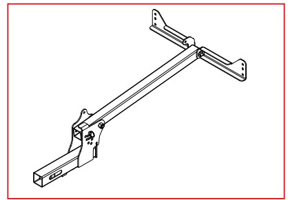
2” RECEIVER BOOM MOUNT ASSEMBLY UTVBR-M
Contents
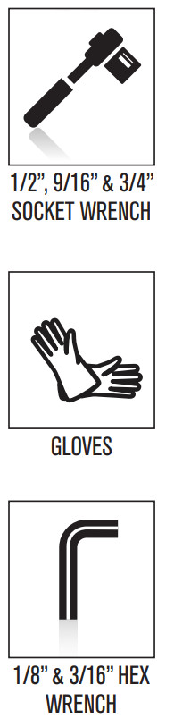
TOOLS REQUIRED
 NOTE:
NOTE:
SPRAYER, BROADCAST SPRAY BOOM AND 5/8” HITCH PIN NOT INCLUDED WITH KIT.
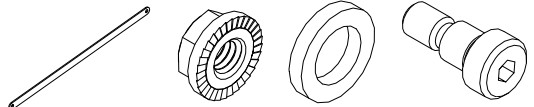
INCLUDED COMPONENTS
 NOTE:
NOTE:
THE 2” RECEIVER BOOM MOUNT IS COMPATIBLE WITH THE FOLLOWING BOOM KITS:
| SSBK-240 – Dual Nozzle Boom Kit | SSBK-NB-2 – Boomless Nozzle Kit |
| SSBK-340 – Three Nozzle Folding Boom Kit | SSBK-DNB-2 – 2GPM Dual Boomless Nozzle Kit |
| SSBK-420 – Four Nozzle Folding Boom Kit | SSBK-DNB-3 – 3GPM+ Dual Bomless Nozzle Kit |
| SSBK-620 – Six Nozzle Folding Boom Kit | SSBK-3TDNB – Dual Boomless w/Single Deflector Kit |
| SSBK-820 – Eight Nozzle Folding Boom Kit | SSBK-PNB – 2 IN 1 Precision & Broadcast Boom Kit |
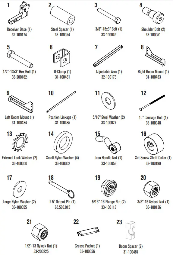
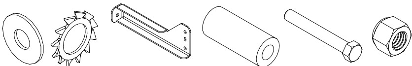
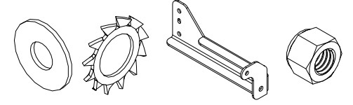
PARTS
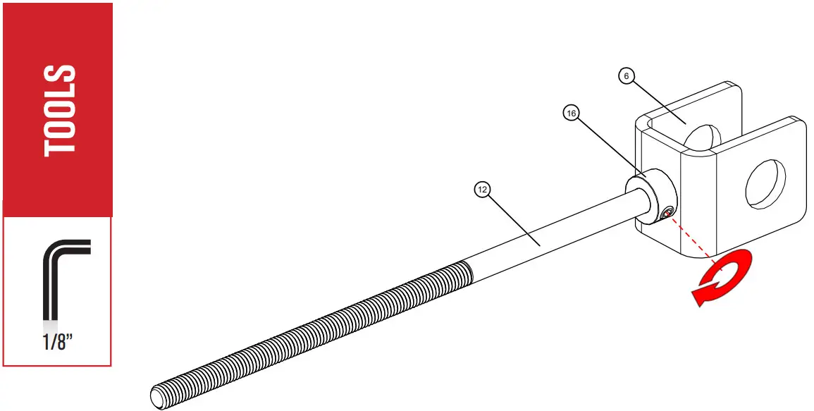
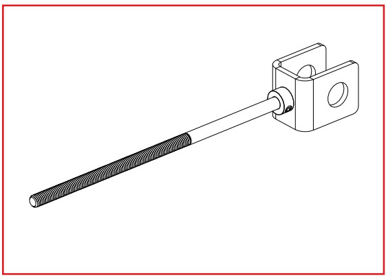
Put 10” Carriage Bolt through the open square hole of the U-Clamp.
Slip on the Set Screw Shaft Collar and tighten it up against the U-Clamp with a 1/8” Hex Key.
Assembles Tension Locking System
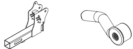
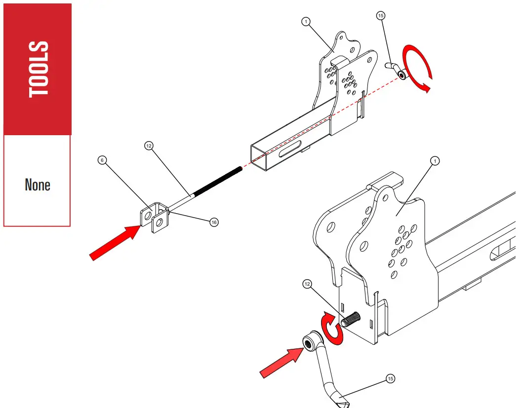 Slide the threaded end of the 10” Carriage Bolt through the open hole end of the Receiver Base.
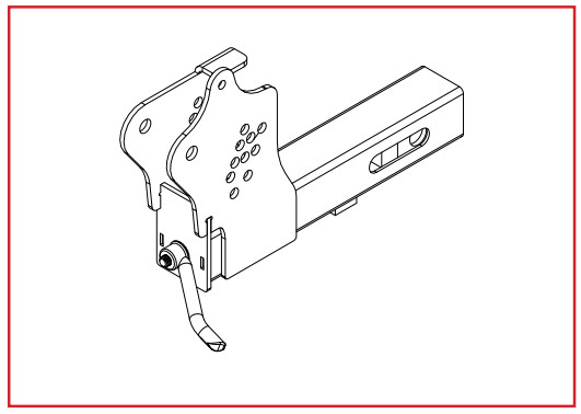
On other side of the Receiver Base, thread the Iron Handle Nut onto the 10” Carriage Bolt.
Attaches Tension Locking System to Receiver Base
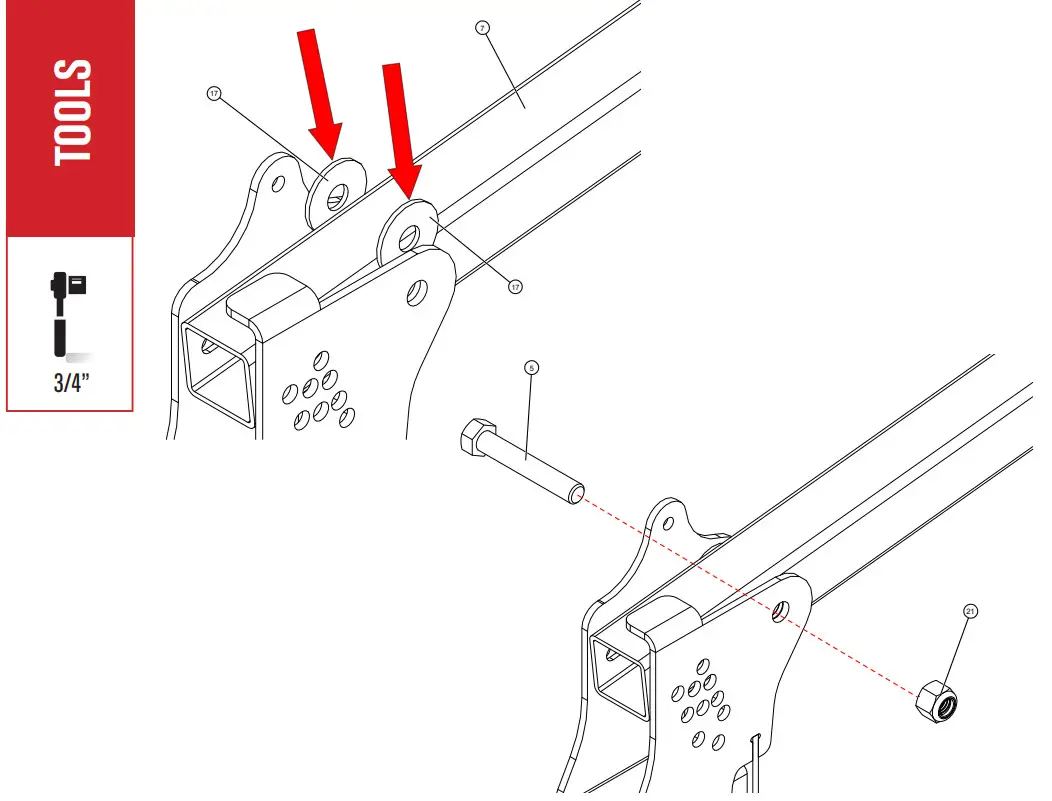 Line up 1/2” holes of the Receiver Base with the 1/2” holes with Adjustable Arm.
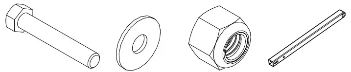
Slide Large Nylon Washer between 1/2” holes of the Receiver Base and Adjustable Arm. Put 3” Hex Bolt
through lined up holes and Large Nylon Washers. Thread ½” Nylock Nut onto 3” Hex Bolt. Tighten with ¾” Socket Wrench.
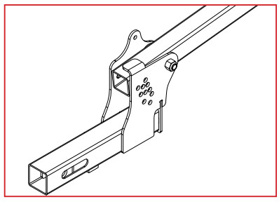
Attaches Adjustable Arm to Receiver Base

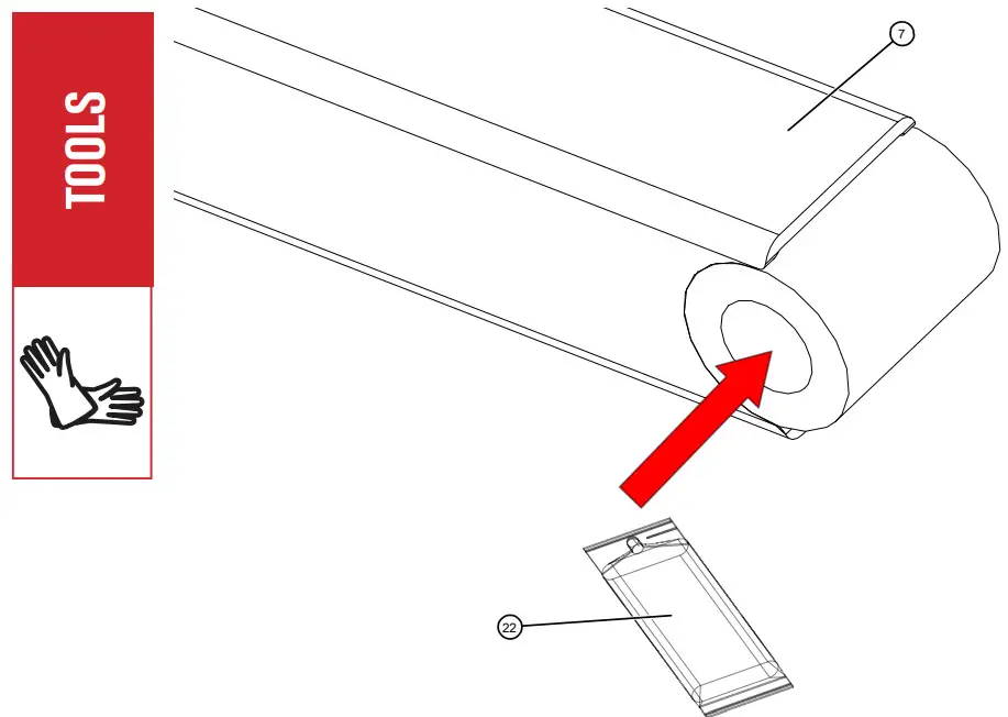 NOTE: To prevent rusting, it is ideal to re-grease the bushing annually.
Put on gloves and tear open the Grease Packet at perforation.
Pour contents of Grease Packet onto the internal surface of the bushing. Spread around evenly.
Greases Bushing On Adjustable Arm

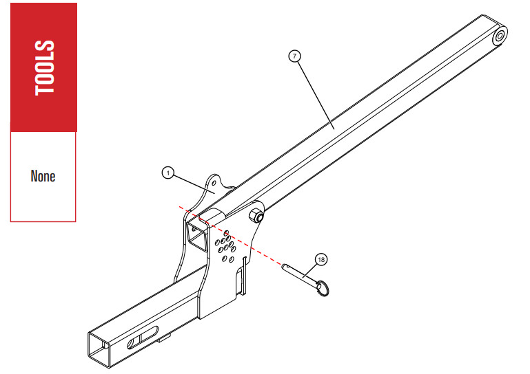 NOTE: The Detent Pin will be utilized when the Adjustable Arm needs to go up or down, based on spraying application. 10 height positions with 1-1/2” adjustments.
Line up holes of Reciever Base and Adjustable Arm.
Insert 2.5” Detent Pin to keep Adjustable Arm stationary.
Locks Adjustable Arm in Position
 TOOLS
TOOLS
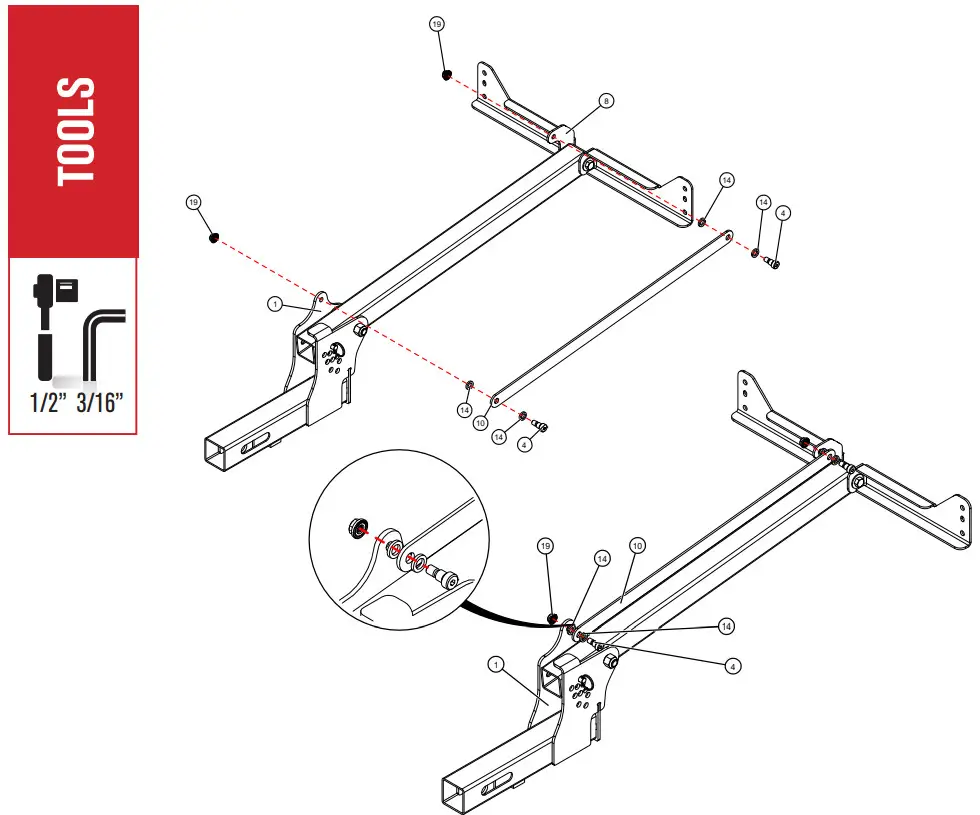
None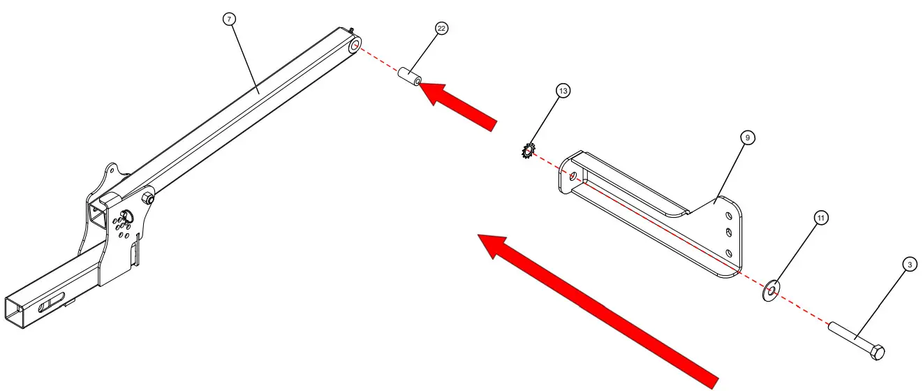 Insert the Steel Spacer into the hole at the end of the Adjustable Arm.
Put 3” Hex Bolt through lined up holes of Steel Washer, Left Boom Mount, and External Lock Washer.
Install into the Steel Spacer Hole.
Attaches Left Boom Mount to Arm
 NOTE: Once assembled, verify alignment of left and right boom mount as depicted. If not aligned, will cause alignment issues in steps #10 & #11. Place assembly with the large flat surface of the left and right boom mount, on the floor, to help with alignment.
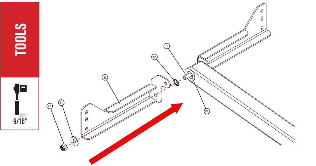
Continue to put 3” Hex Bolt through remaining External Lock Washer, Right Boom Mount and Steel Washer.
Thread 3/8” Nylock Nut to the 3” Hex Bolt. Tighten with 9/16” Socket Wrench.
Attaches Right Boom Mount to Arm
 Line up holes between Receiver Base, Position Linkage, and Small Nylon Washers.
Put Shoulder Bolts through lined up holes.
Thread 5/16” Flange Nut onto Shoulder Bolts. Tighten with ½” Socket Wrench and 3/16” Hex Key.
Repeat step with the other end of Position LinJkage and Left Boom Mount.
Connects Position Linkage to Arm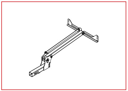
 NOTE: To ensure security, wiggle the Receiver Base during tighten process.
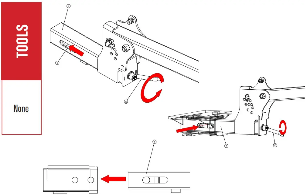
Extend Tensioner to the End of the slot on the Receiver Base by turning the Iron Handle Nut counter clockwise.
Insert the Receiver Base into the Vehicle Hitch Receiver all the way.
Verify that the Receiver Base Holes line up with the Vehicle Hitch Receiver holes.
Insert 5/8” Hitch Pin (not included) and hand tighten the Iron Handle Nut clockwise.
Firmly Secures Mount to Receiver Hitch
Included With Boom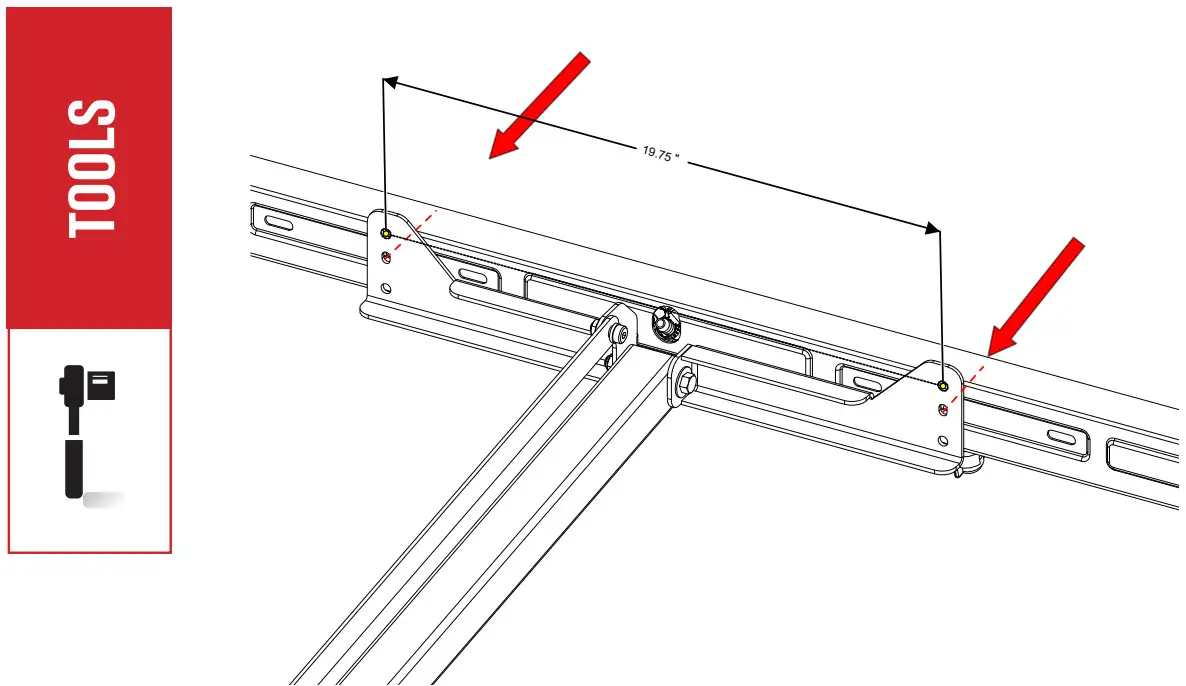 NOTE: Boom Mounting Bolts and Flange Nuts not included. Reference Boom Assembly Card for additional information on mounting hardware and setup. If you have a Boom Assembly that requires U-Bolts for mounting, please skip to Step 11.
Line up holes of the Boom Assembly with the holes of the Left and Right Boom Mounts.
With necessary Bolts and Flange Nuts, install Boom Assembly onto both Boom Mounts. Tighten with Socket Wrench.
Attaches Boom to Mount
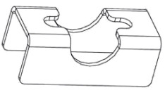
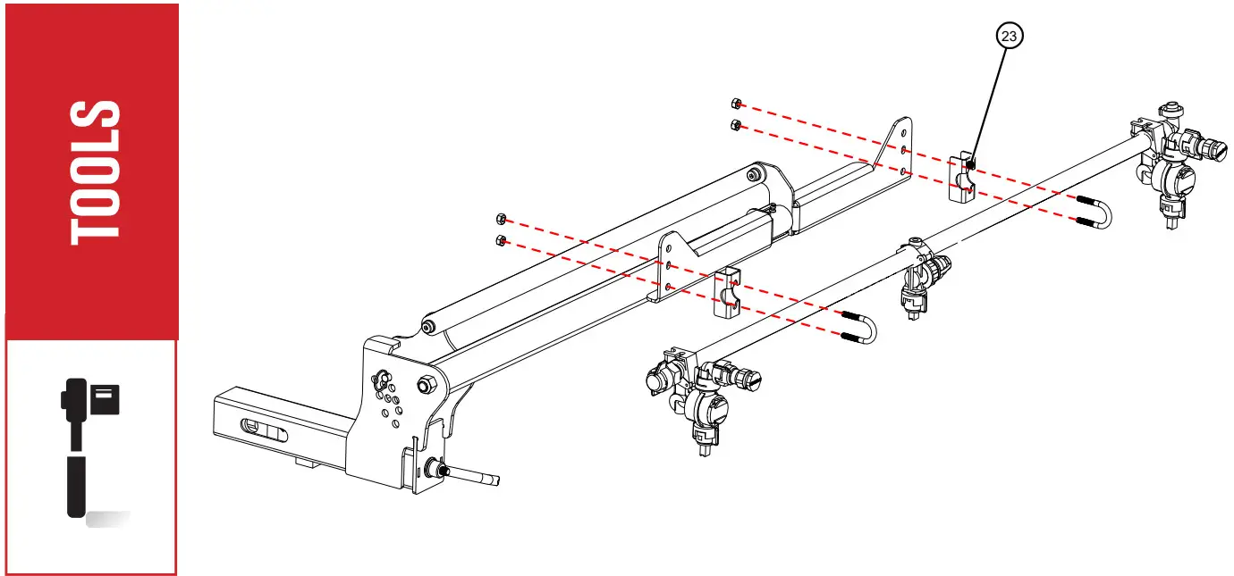 Line up Boom Assembly with holes of Boom Mount and Boom Spacers.
With Necessary U-Bolts and Flange Nuts, install Boom Assembly onto both Boom Mounts.
Tighten with Socket Wrench.
Attaches Alternative Boom to Mount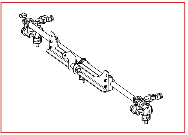
2” RECEIVER BOOM MOUNT ASSEMBLY UTVBR-M