![]() M-SERIES™
M-SERIES™
MGE8-12/14
ELECTRIC COOLING/GAS HEATING
PACKAGED UNIT
Instruction Manual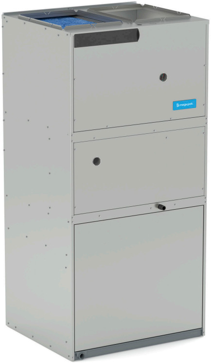
Contents
48MGE8-12-241NP Electric Cooling Gas Heating
FORM NO. MGE8-100 (11/2022)
 www.ahridirectory.org
Unitary Small AC
AHRI Standard 210/240
Certification applies only when the complete system is listed with AHRI.www.ahridirectory.org 
NOTE: MGE8 is not for sale in Canada
MODEL NUMBER GUIDE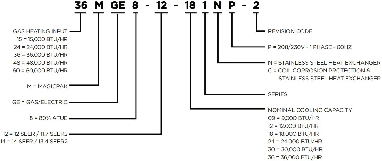 * Check that equipment complies with all applicable building codes, laws, and regulations for its intended use prior to installation.
APPLICATIONS
- MagicPak units are designed for use in allmultifamily applications, such as: apartments,condominiums, student housing and senior living
- Installation in conditioned and non-conditionedmechanical spaces
- Units are approved for installations up to 5,500 ft.without any modifications or adjustments
- For installations above 5,500 ft., refer to HighAltitude Application Data table and installationinstructions for additional details
UNIT APPROVALS
ETL (INTERTEK)
- Design certified by ETL (Intertek) to latest edition of UL 1995
- Certified as a direct vent appliance in accordance with ANSI Z21.47
- Certified for the U.S. only
- Certified for less than 2% cabinet air leakage using ASHRAE Standard 193
- Rated with a 5kA Short Circuit Current Rating (SCCR) in accordance with RMS Symmetrical per UL 508A
- Refer to Unit Electrical and Physical Data table for additional details
AHRI/DOE
- Certified to AHRI Standard 210/240-2008; refer to the AHRI Directory for AHRI certificates
- Cooling and heating system rated in accordance with Department of Energy (DOE) test procedures (latest edition)
- Heating system rated in accordance with Federal Trade Commission (FTC) labeling regulations
CORROSION PROTECTION
- Epoxy coating is specifically designed for use on HVAC type coils and demonstrates 6800+ hours of Sea Water Acetic Acid Testing (SWAAT) per ASTM G85:A3
SOUND RATING
- Outdoor sound level measurements tested per ANSI/AHRI Standard 270
- Refer to Outdoor Sound Rating & Cabinet Air Leakage table for additional details
ALUMINUM LOUVER – PAINT SPECS
- Standard and impact-resistant louvers meet AAMA 2605 specifications
WARRANTY
COMPRESSOR
- Five (5) years limited parts warranty
HEAT EXCHANGER
- Twenty (20) years limited parts warranty on stainless steel heat exchanger
ALL OTHER COVERED COMPONENTS
- Refer to Equipment Limited Warranty for additional details
STANDARD FEATURES
ELECTRICAL CONNECTIONS & GAUGE PORTS
- Line voltage knockouts (two concentric) to accommodate field required wire size
- Thermostat connections are located at the top of the cabinet
- Two gauge ports are located within the lower compartment of the unit
- Refer to Unit Dimension figure for additional details
CABINET
- Embossed galvanized steel cabinet
- Indoor section of the cabinet insulated with 0.5 in. dual density fiberglass insulation
- Outdoor section of the cabinet insulated with 0.5 in. weather-resistant polystyrene insulation
INTERNAL FILTER
- Tool-less filter access
- Factory-installed 1 in. filter rack with washable filter
- Field-supplied filters up to MERV 6 can typically be installed in the filter slot internal to unit in lieu of washable filter, when proper duct design is applied
- If a higher resistance filter is field installed in the unit, the added resistance must be included in the external static pressure and must not exceed 0.5 in. w.c. including ductwork
- Refer to Factory Filter Size and Pressure Drop and Blower Performance tables for additional details
REFRIGERATION SYSTEM
- Factory charged with R-410A refrigerant
- Factory sealed and tested
- **MGE8-14-36*NP-* includes a two-stage compressor
- Refer to Unit Electrical and Physical Data table for additional details
Indoor and Outdoor Coils
- Copper tube with aluminum fin coils
High Pressure Switch
- Shuts off unit if abnormal operating conditions cause the refrigerant discharge pressure to rise above acceptable levels
Low Pressure Switch
- Provides loss of charge protection by shutting off unit if refrigerant liquid pressure falls below acceptable levels
TRANSFORMER
- Rated for 40VA
- Factory wired for 230/240V power supply, and includes field selectable terminal for 208V
- Converts line voltage to 24V for the thermostat and control circuits within the unit
COMBUSTION AIR INDUCER
- Pests are discouraged from nesting in the unit’s flue pipe during summer months by briefly energizing the gas furnace inducer blower at the beginning of each cooling cycle
SUPPLY AIR BLOWER
Constant Torque ECM Blower Motor
- Motor provides specified air volume at 0.1 in. – 0.5 in. w.c. external static pressure
- Blower assembly is easily removed for servicing • Refer to Blower Performance tables for additional details
Electronic Blower Control
- Dedicated blower speed taps for continuous fan, cooling, and heating operation are programmed for optimal airflow and controlled by 24V thermostat signals
- Blower speed adjustment is easily accomplished by speed tap selection
- Fixed blower delays have been selected to enhance comfort
- Refer to Blower Performance tables for additional details
OUTDOOR FAN
- Heavy duty, fully enclosed and weatherproof
- Aluminum fan blades
CONDENSATE MANAGEMENT
Primary Drain Pan
- Antimicrobial protection: drain pan is injected with an antibacterial agent that destabilizes the membrane of microorganism cells, disrupting the cellular function of odor-causing mold and bacteria so that they can no longer grow or reproduce
Overflow Protection
- Indoor drain pan overflow switch monitors the condensate level in primary drain pan
- Prevents unit from running if water is sensed
Secondary Drain Pan
- Polypropylene wall sleeve base is specifically designed to direct rain water out of the building and in the event of any restriction in the primary drain will act as a redundant overflow protection
OPTIONS & ACCESSORIES
FACTORY-INSTALLED OPTIONS
CORROSION PROTECTION
- Epoxy coated indoor and outdoor coils
FIELD-INSTALLED ACCESSORIES
WALL SLEEVES & LOUVERS
- Units must be installed with approved wall sleeve and louver accessories for safe operation and are required for all installations
NOTE: Polypropylene louvers (ALVRP***MGE) should not be oversized - Refer to Wall Sleeves and Louvers table for additional details
WALL SLEEVES (ASLEEVE)
- Penetrates the building envelope and creates a path for condenser air intake and exhaust
- Provides a sealed connection to the unit and a secure attachment foundation for the louvers
- Available in 6 in. to 12 in. depths
WALL SLEEVE EXTENSION (ASLEEVEXT4)
- Provides an additional 4 in. of depth to the wall sleeve, for a maximum depth of 16 in.
LOUVERS
Polypropylene Louvers (ALVRP***MGE)
- Constructed from durable, corrosion-resistant plastic
- Available in four standard colors
Aluminum Louvers (ALVRAL)
- Constructed with 6063-T6 grade aluminum
- Available in anodized clear coat, primer (to be painted in the field), standard paint colors and custom colors with paint matching*
Impact-Resistant Aluminum Louvers (ALVRALC)
- Impact and wind load certified up to 186 MPH, risk categories III and IV, and wind exposures C and D
• ALVRALC-1 & ALVRALC-2: FBC Notice of Acceptance (NOA) 20-0909.03
• ALVRALC-3, -4 & -7: FBC Notice of Acceptance (NOA) 21-1216.11 - Constructed with 6063-T6 grade aluminum
- Available in anodized clear coat, primer (to be painted in the field), standard paint colors and custom colors with paint matching*
LIQUID PROPANE (LP) CONVERSION KIT (ALPKT*)
- Enables simple conversion from natural gas to liquid propane
- Refer to LP Conversion Kit table for additional details
SHORT CIRCUIT CURRENT RATING KIT (ASCCR)
- Provides 200kA of SCCR protection
- Refer to SCCR Accessory table for additional details
FILTERS
- Field-supplied filters up to MERV 6 can typically be installed in the filter slot internal to unit
NOTE: Use of paper frame not recommended
CRANKCASE HEATER (ACASE841)
- Warms compressor crankcase to limit migration of liquid refrigerant back to compressor during off cycle
- Available for models with scroll compressors
- Refer to Crankcase Heater table for additional details
THERMOSTAT
- Required for all installations (field-supplied)
- Units are individually controlled with conventional 24V thermostat
- One-stage Cool/Heat required for 0.75 to 2.5 ton
- Two-stage Cool/One-stage Heat required for 3.0 ton
UNIT ELECTRICAL AND PHYSICAL DATA (208/230 Volt – 1 Phase – 60HZ)¹
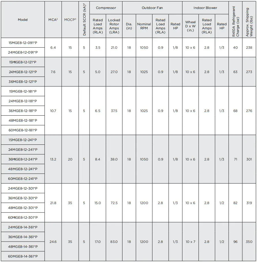
- Acceptable voltage range: 197 – 253V
- MCA = Minimum Circuit Ampacity
- MOCP = Maximum Over Current Protection
- SCCR = Short Circuit Current Rating; refer to SCCR Accessory table, up to 200kA
NOTE: Units are rated at 208/230V, but MOCP & MCA values are calculated at 240V
UNIT DIMENSIONS (IN.)
| Model | A | B | C | D | E |
| *MGE8-12-091*P *MGE8-12-121*P |
57-7/8 | 20-3/4 | 18-5/8 | 6 | 24-5/ |
| *MGE8-12-181*P *MGE8-12-241*P |
59-7/8 | 22-3/4 | 20-5/8 | 26-5/8 | |
| *MGE8-12-301*P | 63-7/8 | 26-3/4 | 24-5/8 | 30-5/8 | |
| *MGE8-14-361*P | 71-7/8 | 34-3/4 | 28-5/8 | 10 | 38-5/8 |
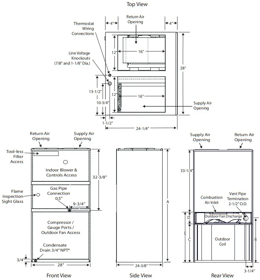 * Provisions must be made to properly drain condensate from the drain pan.
MINIMUM CLEARANCES
Accessibility Clearances
The front of the unit must be accessible for service. A minimum clearance of 30” in front of unit is required for service.
If the unit is enclosed, a door or access panel aligned with the front of the unit is the preferred method of providing access.
The door or access panel opening must be a minimum of 30” wide (centered on the unit) and be as tall as the unit.
IMPORTANT
The unit must be installed with approved wall sleeve and louver accessories for safe operation.
Improper installations could result in property damage, personal injury, or death.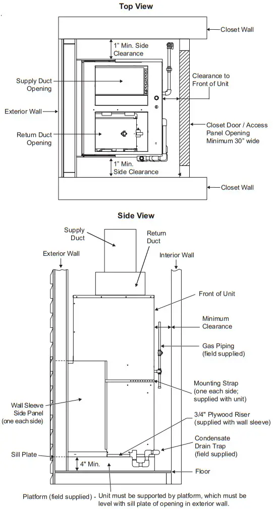 Supply Duct Clearances
| Minimum Clearances to Combustible Materials1 | ||
| Front | Sides | Top |
| 0” | 0” | 0” |
- Accessibility clearances take precedence
Unit Clearances
| Minimum Clearances1 | |
| Front² | Sides³ |
| 1” | 1” |
- Accessibility clearances take precedence
- Clearance must accommodate field-installed condensate drain line / drain trap and gas line
- Additional clearance required if field-installed condensate drain line / drain trap is routing alongside unit
NOTE: Consult local codes for other clearance requirements
OUTDOOR SOUND RATING & CABINET AIR LEAKAGE
| Model | Outdoor Sound Rating (dBa)1 | Cabinet Air Leakage (%)2 |
| *MGE8-12-091*P | 75 | 2.0 |
| *MGE8-12-121*P | 75 | 2.0 |
| *MGE8-12-181*P | 75 | 1.4 |
| *MGE8-12-241*P | 76 | 1.4 |
| *MGE8-12-301*P | 81 | 1.4 |
| *MGE8-14-361*P | 75 | 1.4 |
- Per ANSI / AHRI Standard 270
- Per ASHRAE Standard 193
FACTORY FILTER SIZE (IN.) AND PRESSURE DROP (IN. W.C.)
| Model | Filter Size | Indoor Airflow (CFM) | |||||||||||||||||
| 200 | 250 | 300 | 350 | 400 | 450 | 500 | 550 | 600 | 650 | 700 | 750 | 800 | 850 | 900 | 950 | 1000 | 1050 | ||
| All | 12 x 24 x 1 1 | 0.01 | 0.02 | 0.03 | 0.04 | 0.04 | 0.05 | 0.08 | 0.09 | 0.10 | 0.12 | 0.14 | 0.15 | 0.17 | 0.18 | 0.20 | 0.22 | 0.24 | 0.26 |
SCCR ACCESSORY
| Model | Kit1 |
| *MGE8-12-091*P | ASCCR1 |
| *MGE8-12-121*P | |
| *MGE8-12-181*P | |
| *MGE8-12-241*P | |
| *MGE8-12-301*P | ASCCR3 |
| *MGE8-14-361*P |
CRANKCASE HEATER
| Model | Kit |
| *MGE8-12-091*P | N/A |
| *MGE8-12-121*P | |
| *MGE8-12-181*P | |
| *MGE8-12-241*P | |
| *MGE8-12-301*P | ACASE841 |
| *MGE8-14-361*P |
LP CONVERSION KIT
| Model | Kit |
| 15MGE8-12-**1*P | ALPKT613 |
| 24MGE8-12/14-**1*P | ALPKT614 |
| 36MGE8-12/14-**1*P | |
| 48MGE8-12/14-**1*P | |
| 60MGE8-12/14-**1*P |
HIGH ALTITUDE APPLICATION DATA
| Altitude | Natural Gas | LP Gas | ||
| Burner Orifices | Manifold Pressure | Burner Orifices LP Kit | Manifold Pressure | |
| 0-5,500 ft. | As shipped | 3.5” w.c. | ALPKT613 or 614 (model dependent) |
10.0” w.c. |
| 5,500 – 8,500 ft. | 3.0” w.c. | 8.0” w.c. | ||
| Above 8,500 ft. | Per National Fuel Gas Code | 3.5” w.c. | Per National Fuel Gas Code | 10.0” w.c. |
WALL SLEEVES & LOUVERS
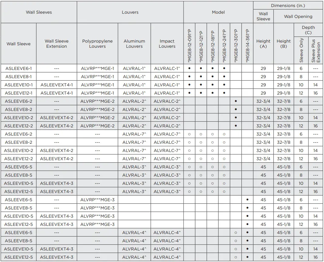
*** Louver colors: WHT = white, SAN = sandstone, BGE = beige, TPST = taupestone
^ -P: Option to paint standard, aluminum, and impact-resistant louver
○ Optional: Wall sleeves and louvers can be oversized to maintain a uniform appearance
NOTE: ALVRP**MGE louvers may not be oversized due to vent pipe and metal grate insert location
WALL SLEEVE & WALL OPENING DIMENSIONS (IN.)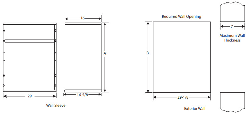
RATED COOLING & HEATING PERFORMANCE
| Model | Cooling | Gas Heating | ||||||
| Net Capacity (Btu/hr) | Efficiency | S/T^ | Input (Btu/hr) | Output (Btu/hr) | Rise Range (F°) | Efficiency AFUE (%) | ||
| SEER / EER | SEER2 / EER2 | |||||||
| 15MGE8-12-091*P | 8,600 / 8,600 | 12.0 / 11.0 | 11.7 / 10.0 | 0.77 | 15,000 | 12,000 | 15 – 45 | 80 |
| 24MGE8-12-091*P | 24,000 | 19,200 | 25 – 55 | |||||
| 15MGE8-12-121*P | 12,000 / 12,000 | 12.0 / 11.0 | 11.7 / 10.5 | 0.7 | 15000 | 12000 | 15 – 45 | 80 |
| 24MGE8-12-121*P | 24000 | 19200 | 25 – 55 | |||||
| 36MGE8-12-121*P | 36000 | 28800 | 30 – 60 | |||||
| 15MGE8-12-181*P | 17,200 / 16,900 | 12.5 / 11.0 | 11.7 / 10.0 | 0.77 | 15000 | 12000 | 15 – 45 | 80 |
| 24MGE8-12-181*P | 24000 | 19200 | 25 – 55 | |||||
| 36MGE8-12-181*P | 36000 | 28800 | 30 – 60 | |||||
| 48MGE8-12-181*P | 48000 | 38400 | 35 – 65 | |||||
| 60MGE8-12-181*P | 60000 | 48000 | 40 – 70 | |||||
| 15MGE8-12-241*P | 22,600 / 21,800 | 13.0 / 11.0 | 11.7 / 10.0 | 0.77 | 15000 | 12000 | 15 – 45 | 80 |
| 24MGE8-12-241*P | 24000 | 19200 | 25 – 55 | |||||
| 36MGE8-12-241*P | 36,000 | 28,800 | 30 – 60 | |||||
| 48MGE8-12-241*P | 48,000 | 38,400 | 35 – 65 | |||||
| 60MGE8-12-241*P | 60,000 | 48,000 | 40 – 70 | |||||
| 24MGE8-12-301*P | 28,200 / 27,600 | 12.0 / 11.0 | 11.7 / 10.0 | 0.73 | 24000 | 19200 | 25 – 55 | 80 |
| 36MGE8-12-301*P | 36000 | 28800 | 30 – 60 | |||||
| 48MGE8-12-301*P | 48000 | 38400 | 35 – 65 | |||||
| 60MGE8-12-301*P | 60000 | 48000 | 40 – 70 | |||||
| 24MGE8-14-361*P | 34,200 / 31,800 | 14.0 / 11.0 | 13.4 / 10.6 | 0.72 | 24000 | 19200 | 25 – 55 | 80 |
| 36MGE8-14-361*P | 36000 | 28800 | 30 – 60 | |||||
| 48MGE8-14-361*P | 48000 | 38400 | 35 – 65 | |||||
| 60MGE8-14-361*P | 60000 | 48000 | 40 – 70 | |||||
^ Not a rated value
S/T = ratio of sensible to total cooling load
For most up to date ratings and values, please view AHRI listing
EXTENDED COOLING PERFORMANCE DATA
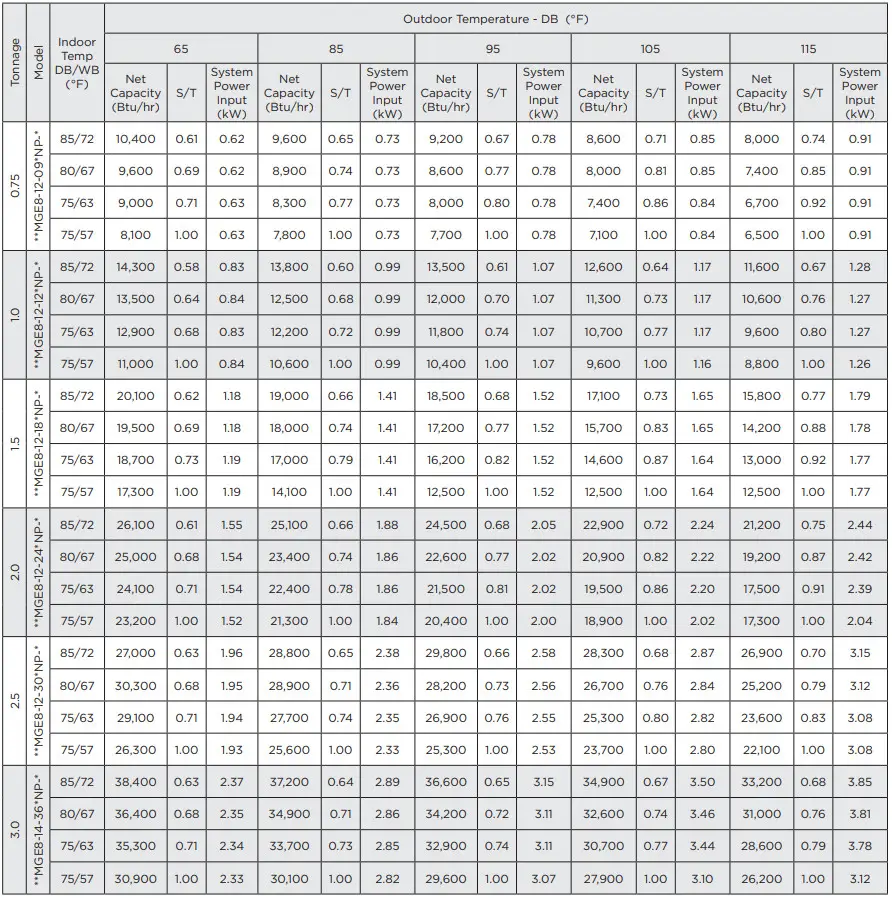 NOTE: Values based on 0.1” w.c. external static pressure
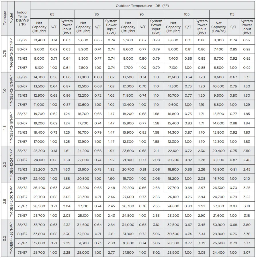 NOTE: Values based on 0.3” w.c. external static pressure for **MGE8-12-09*NP-*, ***MGE8-12-12*NP-*, **MGE8-12-18*NP-*, ***MGE8-12-24*NP-*, **MGE8-12-30*NP-*, and 0.5” w.c. external static pressure for **MGE8-12-36*NP-*
BLOWER PERFORMANCE
- Performance based on factory-provided washable filter installed in the unit.
- If a higher resistance filter is field installed in the unit, the added resistance must be included in the external static pressure and must not exceed 0.5 in. w.c. including ductwork
- Refer to Factory Filter Size and Pressure Drop table for additional details
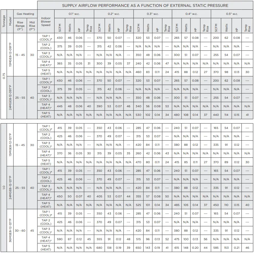
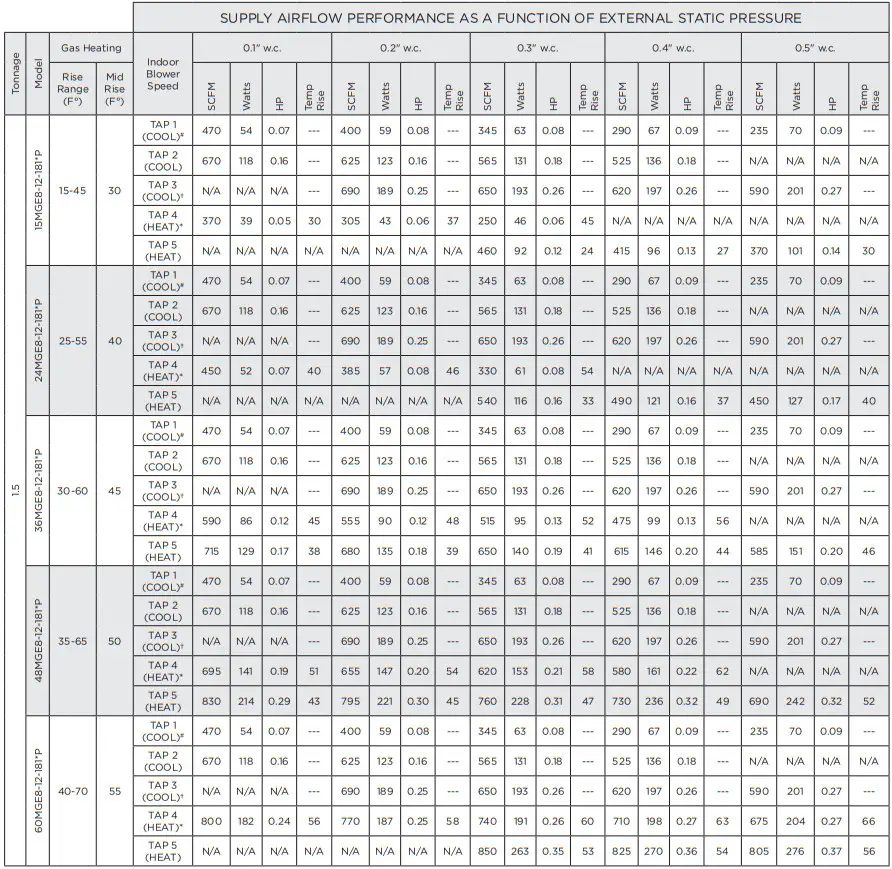
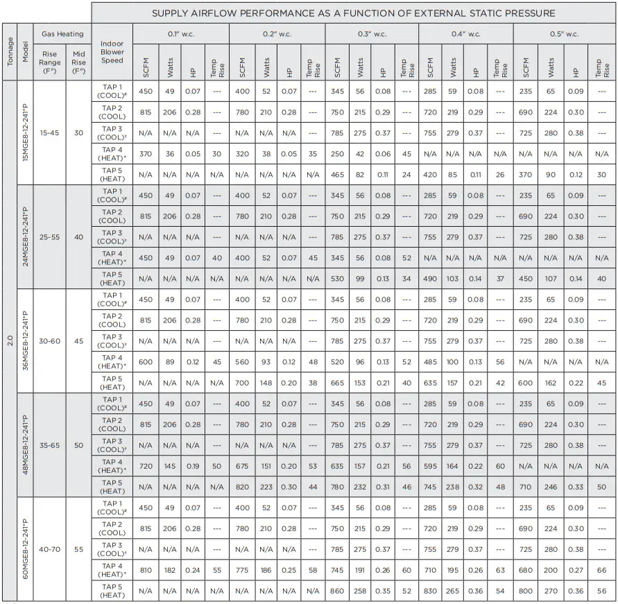

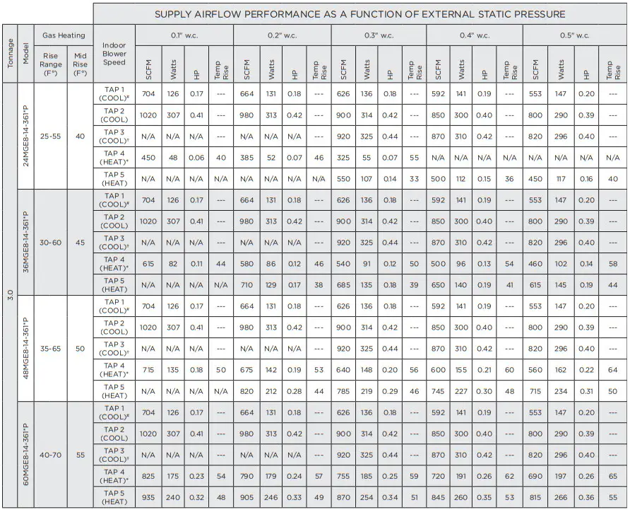 N/A: Do not operate unit using this blower speed at this external static pressure.
† As shipped speed for Cooling operation. Blower speed must be field adjusted to speed Tap 2 for lower duct static applications.
* As shipped speed for Heating operation. Blower speed must be field adjusted to speed Tap 5 for higher duct static applications.
# As shipped speed for Low Stage Cooling operation (low duct static).
SCFM = standard cubic feet per minute
All specifications and illustrations subject to change without notice and without incurring obligations.
FORM NO. MGE8-100 (11/2022)
![]() 215 Metropolitan Drive | West Columbia, SC 29170
215 Metropolitan Drive | West Columbia, SC 29170
800-448-5872
Product Support 866-282-7257
www.magic-pak.com
© 2022 Allied Air Enterprises LLC, a Lennox International Inc. Company
Printed in the U.S.A.