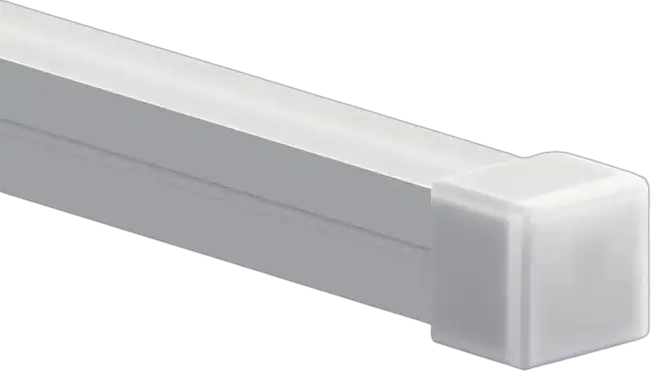
LUMENTRUSS SÉRIE NEON SLEEVE SERIES Top View Flex Instruction Manual
Contents
FEUILLE D’INSTALLATION / INSTALLATION SHEET
Install the mounting brackets (a) on the desired surface using provided
screws (b).
Install the Neon Sleeve (c) into brackets. Make electrical connections (pp.3-4).
ENDCAPS AND WIRING OPTIONS
Front Hardwire
Front DC Plug
Closed Endcap
WIREWAY EXAMPLE
NSTALLATION OPTIONS
Curved installation – min. inner bend radius 150mm (6”).
Straight installation.
MISE EN GARDE / WARNING
Minimum inner bend radius 150mm (6in).
LT_ Neon-Sleeve-Top-View-Flex_ IS
Up/down bend. The Neon Sleeve can only be bent in the direction perpendicular to the LED strip (see diagram below).
UP/DOWN BEND
- DO NOT PULL
- DO NOT BEND
- DO NOT TWIST
- DO NOT PIERCE
FRAGILE ELECTRONIC COMPONENTS HANDLE WITH GREAT CARE
COMPOSANTS COMPONENT PARTS
- a- PVC brackets
- b- Mounting screws
- c- TVF Neon Sleeve d0, d1 – Endcaps
- e- LED tape
ELECTRICAL CONNECTIONS
WARNING: RISK OF ELECTRIC SHOCK
To prevent electric shock, power should be turned off from the electrical panel before installation or maintenance process. INSTALLATION MUST COMPLY WITH ALL CURRENT NATIONAL AND LOCAL ELECTRICAL CODES.
LOW VOLTAGE CONNECTION
A HARDWIRE CONNECTION
- Join the black wire from the LED tape (1) (-) with the black output wire from the low voltage power supply (2).
- Join the white or red LED tape wire (+) to the white or red power supply output wire.
- Use appropriate twist-on (or equivalent) connectors to isolate wires.
B PLUG-IN CONNECTION WITH DC PLUG
Connect input connector of the LED tape (1) to the output connector of the low voltage power supply (2).
LINE VOLTAGE CONNECTION
- Pass the main power feed (not included) and power supply input cable (3) into junction box (not included).
- Connect the white (N, Neutral) cables from the power feed and from the power supply.
- Connect the black (L, Live) cables from the power feed and from the power supply.
- Connect the copper, green or yellow (G, ground) wires from the power supply, power feed, and the junction box. Use appropriate twist-on connectors (not included).
- Install the junction box cover (not included)
WIRING DIAGRAMS
LOW VOLTAGE CONNECTION (LED TO POWER SUPPLY)
Non-dim. / ELV / TRIAC
0-10 V

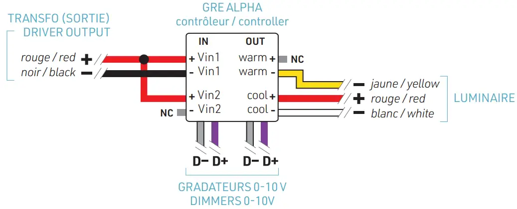
TUNABLE WHITE CONTROLLER
GRE ALPHA CONTR. (BLANC AJUSTABLE / TUNABLE WHITE)
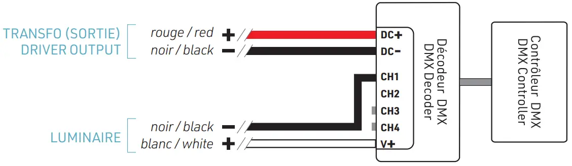
RGB(W) CONTROLLER

DMX
SINGLE COLOR (2 PINS)
TUNABLE WHITE (3 PINS)

RGB (4 BROCHES) / RGB (4 PINS)

LINE VOLTAGE CONNECTION (POWER SUPPLY TO AC MAINS)
Non-dim. / 0-10V / DMX / RGB contr. / GRE Alpha

TRIAC
ALIMENTATION AC AC POWER FEED

ELV
ALIMENTATION AC AC POWER FEED

WARNING:
Use only Class 2 rated components.
9221, Rue H1J 1T4 Lumen Truss reserves the rights to make changes to this document at any time without prior notice
www.lumentruss.com / 1 855 384 3384 / 1 514 903 5863 / 9221, Rue Edison,
Lumen Truss reserves the rights to make changes to this document at any time without prior notice.