![]() EPIC® SENSORS
EPIC® SENSORS
TRACE HEATING SENSOR
TYPE W-M-TRACE, 2xW-M-TRACE
DATA SHEET 23
INSTALLATION INSTRUCTIONS
AND USER MANUAL
Contents
Product description and intended use
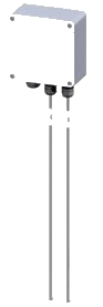
Sensor types W-M-TRACE and 2xW-M-TRACE (resistance, RTD) are temperature sensors for trace heating applications, constructed with one or two mineral insulated sensors and a terminal box.
Sensors are intended for measuring trace heated pipe surfaces. The 2-sensor version can be used when a separate temperature measurement is wanted for limit/alarm purpose, leaving the other sensor clearly for control circuits.
The sensor elements can be designed long enough to give needed distance between heat source (pipe) and box/enclosure. Standard lengths are 1000 mm or 2000 mm. Sensor element protection tube material can be chosen, and element length can be produced according to customer needs.
Measuring elements are mineral insulated (MI) elements, which are bendable. Elements are RTD elements, standard versions are 4-wire Pt100 sensors. Tailored versions are produced on request.
NOTE!
Also available with ATEX approved, protection type Ex e components.
Please see section Ex data.
When used as part of an installation, subsequent approval of the entity is required.
EPIC® SENSORS temperature sensors are measuring devices intended for professional use. They should be
mounted by professionally capable installer who understands the installations surroundings. The worker should understand mechanical and electrical needs and safety instructions of the object installation. Suitable safety gear for each installation task must be used.
Temperatures, measuring
Allowed measuring temperature range for cable sensor tip is:
- Standard (non-Ex), sensor type W-M-302 -200…+450, temporarily +550 °C
- Ex e, cable sensor type WT-MI-302-…-EX -60…+550 °C
Temperatures, ambient
Allowed ambient temperatures for Ex cable sensors; please see section Temperatures, Ex e components.
Allowed ambient temperature range for enclosure is:
- Standard box -40…+80 °C
- Ex enclosures please see Ta classes in section Technical data.
Allowed ambient temperature range for terminal connectors is:
- Standard -55…+85 °C
Temperatures, Ex e components
NOTE! W-M-TRACE assembly can be equipped with Ex e approved components.
When used as part of an installation, subsequent approval of the entity is required.
Sensors:
If Ex e version cable sensors are used, the sensor types are: WT-MI-302-….-.
Allowed measuring temperature range for sensor tip is: -60…+550 °C.
With these Ex e cable sensor types, specific conditions apply according to the ATEX certificates.
For type WT-MI-302-6-…-EX, certificates EESF 18 ATEX 049 Issue 1 and EESF 18 ATEX 051 Issue 1:
The temperature classification of the sensor (550 °C, T1 – T6) is determined by tre ambient temperature of the installation place.
Maximum ambient temperature is 550 °C for the sensor head and 125 °C for the connection terminals of the sensor cable.
Enclosures:
- for Ex e enclosure please see Technical data for Ta classes.
- for terminal connectors -55…+85 °C
Please see also section Ex data.
Code key

Technical data
| Materials | AISI 316L, maximum temperature +450 °C, temporarily +550 °C, other materials on request |
| Tolerances Pt100 (IEC 60751) | A tolerance ±0.15 + 0.002 x t, operating temperature -100…+450 ‘C B tolerance ±0.3 + 0.005 x t, operating temperature -196…+600 °C B 1/3 DIN, tolerance ±1/3 x (0.3 + 0.005 x t), operating temperature -196…+600 °C B 1/10 DIN, tolerance ±1/10 x (0.3 + 0.005 x t), operating temperature -196…+600 -C |
| Temperature range Pt100 | -60…+450 °C, temporarily +550 °C |
| Sensing element classification | II 2 GD Ex e T1-T6 Ex tD A21 IP66 T 60 °C T amb (max.) -40…+125/550 ‘C |
| Length | 1000 or 2000 mm as standard delivery, other lengths on request |
| Diameter | 3 or 6 mm, other diameters on request |
| Enclosure dimensions | 160x160x90 mm (WxHxD) |
| Enclosure material | Glass-reinforced polyester as standard delivery, other materials on request |
| Enclosure classification | II 2 GD Ex e IIC T6 Gb (Ta = -65…+40°C, +55°C, +60°C or +65°C) Ex e IIC T4 Gb (Ta = -65°C…+90°C) Ex lb IIC T6 Gb (Ta = -65°C…+40°C, +55°C, +60°C or +65°C) Ex lb IIC T4 Gb (Ta = -65°C…+90°C) Ex tb IIIC T85°C Db (Ta = -65°C…+40°C, +55°C, +60°C or +65°C) Ex tb IIIC T100°C Db (Ta = -65°C…+90°C) |
| Box temperature range | -40…+80 °C |
| Cable glands | Product with 2 sensing elements: 1 x cable gland, M25x1.5, for cable diameters 6-13 mm Product with 1 sensing element: 2 x cable gland, M25x1.5, for cable diameter 6-13 mm |
| Approvals | Available with Ex e approved components, subsequent approval of the entity is required. |
| Quality certificate | ISO 9001:2015 and ISO 14001:2015 issued by DNV |
| IP rating | IP66 or IP67, other IP rating on request |
Materials
These are the standard materials of components for the sensor types W-M-TRACE, 2xW-M-TRACE.
| • Sensor element / MI cable sheet | AISI 316L |
| • Enclosure | Glass-Reinforced Polyester GRP |
| • Cable glands | Polyamide with CR/Special Elastomer seal |
| • Contact terminals | Polyamide PA66 |
Other materials can be used on request.
Dimensional drawing
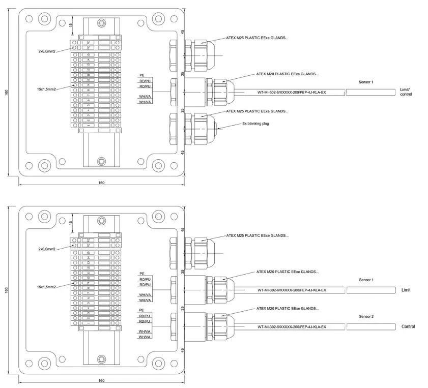
This example drawing above is presenting an application with Ex e approved components. For details about Ex applications, please see section Ex data.
Installation instructions and example
Before any installation, make sure the target process/machinery and site are safe to work!
Installation phases:
- Install the box/enclosure on wall, considering the length of sensors.
- During installation, remember the MI element minimum bending radius is 2x ØOD of the element.
- Do not bend the tip (30 mm) of RTD sensing elements, it might destroy the resistor inside.
- Bend the sensor elements to align them with the pipe surface.
- Mount the sensor securely on pipe with pipe clamps or cable ties or similar accessories.
- Mount the pipe isolation if needed.
- Make sure there is no excess bending force loading the sensing element.
Image below: this example shows a sensor installed on trace heated process pipe.

Installation of accessories
Pipe fittings = pipe clamps:
There are stainless steel (1.4401) pipe clamp (hose clamp) components available as accessories.
Installation phases:
- Select a suitable clamp size according to the pipe diameter.
- Or select a separate, 1 m long strap part, and cut it in pieces of suitable lengths. Separate clamp parts for the strap can be ordered according to the need. Insert a clamp part to one end of the band.
- Apply the strap around the pipe, leaving the sensor element under the strap.
- Tighten the strap by twisting the screw clockwise, to give a secure thermal connection between sensor and pipe surface.
The components available are:
| Product number | Type | Strap length/width | Material |
| 915589 | Pipe clamp | 16-27/12MM | 1.4401 |
| 1125786 | Pipe clamp | 25-40/12MM | 1.4401 |
| 1125787 | Pipe clamp | 32-50/9MM | 1.4401 |
| 1026077 | Pipe clamp | 50-70/12MM | 1.4401 |
| 1228601 | Pipe clamp | 70-90/12MM | 1.4401 |
| 5120444 | Pipe clamp | 90-110/12MM | 1.4401 |
| 5120446 | Pipe clamp | 110-130/12MM | 1.4401 |
| 5120448 | Pipe clamp | 130-150/12MM | 1.4401 |
| 920556 | Pipe strap | 1METER/12MM | 1.4401 |
| 920559 | Pipe strap clamp | 12MM | 1.4401 |

Tightening torques
Use only tightening torques allowed in applicable standards of each thread size and material.
Pt100; connection terminals
In the terminal box / enclosure free wire ends of sensors are available, but they are not connected to terminals, to give the customer freedom of choosing terminals.
Pt100; connection

Wires are not connected, connected can be realized according to customer specification
Pt100; connection wiring
Image below: These are the connection colors of Pt100 resistor connections, according to standard EN 60751
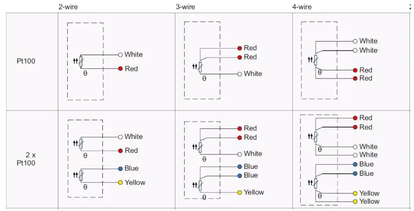
Other connections on request.
Pt100; measuring current
The highest allowed measuring current for Pt100 measuring resistors depends on resistor type and brand.
Normally the recommended maximum values are:
| • Pt100 | 1 mA |
| • Pt500 | 0,5 mA |
| • Pt1000 | 0,3 mA. |
Do not use higher measuring current. It will lead to false measurement values and might even destroy the resistor.
Type label of standard versions
Each sensor has a type label attached to. It is a moisture and wear proof industrial grade sticker, with black text on white label. This label has printed information of trade name, web page, type code, CE-mark, product number and serial number, including production date. For these sensors manufacturer contact information is printed on a separate label.
Image below: Example of a non-Ex sensor type label.

Serial number information
Serial number S/N is always printed on type label in the following form: yymmdd-xxxxxxx-x:
| ▪ yymmdd | production date, e.g. “210131” = 31.1.2021 |
| ▪ -xxxxxxx | production order, e.g. “1234567” |
| ▪ -x | sequential ID number within this production order, e.g. “1” |
Ex e data (only for cable sensor components with Ex e approval)
If the trace heating sensor assembly W-M-TRACE is constructed with Ex e components, the cable sensor types are WT-MI-302-…-EX.
These Ex e cable sensor types are available with ATEX and EAC Ex approvals. The approved types are special versions, with type designation ending with -EX. Special data for use in Ex e applications is given in certificates.
Ex certificates and Ex markings of cable sensor components
| Type Certificate number |
Issued by | Applicable area | Marking |
| WT-MI-302-6-…-EX | |||
| ATEX EESF 18 ATEX 049X, EESF 18 ATEX 051X |
Eurofins Expert Services Oy, Finland, Notified BodyNr 0537 |
Europe | Ex II 2GD Ex e II T1-T6 Ex tD A21 IP66 T+60°C Tamb: -40…+125°C/+550°C |
| EAC Ex № ЕАЭС RU CFI.AA71.B.00130-19 |
Lenpromexpertiza OOO, Russia |
Eurasian Customs Union (Belarus, Kazakhstan, Russia) |
1 Ex e IIC T6…T1 Gb X Ex tb IIIC T60°C Db X |
For certificate copies and special Ex e product data, please visit:
https://www.epicsensors.com/en/products/temperature-sensors/exe-extb-temperature-sensors/
NOTE! When used as part of an installation, subsequent approval of the entity is required.
Ex e type label of cable sensor components
NOTE!
These Ex e type labels are attached on and they only apply for cable sensor elements, which are used as components.
For ATEX Ex e -approved WT-MI-302-…-EX cable sensor Ex e versions there is more information on the label, according to applicable standards.
Image below: Example of an ATEX Ex e approved cable sensor type label.

For EAC Ex e approved WT-MI-302-…-EX cable sensor versions, exported to Eurasian Customs Union area, there is a special type label.
Image below: Example of an EAC Ex-approved cable sensor type label.

EU Declaration of Conformity
The EU Declaration of Conformity, declaring products‘ conformance to the European Directives, is delivered with products or sent on request.
Manufacturer contact information
Manufacturer HQ main office:
| Street address Postal address |
Lapp Automaatio Oy Martinkyläntie 52 FI-01720 Vantaa, Finland |
Production site and logistics:
| Street address Postal address Phone (sales) Https |
Lapp Automaatio Oy Varastokatu 10 FI-05800 Hyvinkää, Finland +358 20 764 6410 [email protected] www.epicsensors.com |
Document history
| Version / date | Author(s) | Description |
| 20220822 | LAPP/JuPi | Telephone number update |
| 20220401 | LAPP/JuPi | Original version |
Although every reasonable effort is made to ensure the accuracy of the content of the operating instructions, Lapp Automaatio Oy is not responsible for the way the publications are used or for possible misinterpretations by end users. The user must ensure that she or he has the latest edition of this publication.
We reserve the right to make changes without prior notice. © Lapp Automaatio Oy
![]()