![]()
SET-2000
110 VAC supply voltage
Level switch for two sensors
![]()
Installation and Operating Instructions

Copyright © 2022 Labkotec Oy
We reserve the right for changes without notice
SET-2000 (110 VAC)
D15349AE-3
Installation and Operating Instructions
Contents
SET-2000 VAC Supply Voltage
SYMBOLS
| Warning / Attention | |
| Pay attention to installations at potentially explosive atmospheres | |
| Device is protected by double or reinforced insulation |
GENERAL
SET-2000 is a two-channel level switch. Typical applications are high level and low level alarms in liquid tanks, condensed water alarms, level control and alarms in oil, sand and grease separators.
The LED indicators, push buttons and interfaces of the device are described in figure 1.

Figure 1. SET-2000 level switch – features
SET-2000 user interface features:
- LED indicator for mains
- LED indicators of alarm and fault for both sensors
- Reset button for alarm and fault
- Test button
- Connectors for two Labkotec SET level sensors [Ex ia]
- Potential-free relay outputs for monitoring and control purposes
SET-2000 can be used as a controller of level sensors located in potentially explosive atmospheres (zone 0,1 or 2) due to intrinsically safe inputs of the device. The SET-2000 itself must be installed in a non-hazardous area.
The level sensors, which are connected to SET-2000, can be installed in zones of different classification, because the channels are galvanically isolated from each other.

Figure 2. Typical application. High level and low level alarm in a liquid vessel.
INSTALLATION
The SET-2000 can be wall-mounted. The mounting holes are located in the base plate of the enclosure, beneath the mounting holes of the front cover.
The connectors of the external conductors are isolated by separating plates. The plates must not be removed. The plate covering the connectors must be installed back after executing cable connections.
The cover of the enclosure must be tightened so, that the edges touch the base frame. Only then do the push buttons function properly and the enclosure is tight.
Before installation, please read the safety instructions in chapter 6 !

- Supply voltage 110 VAC, 50/60 Hz
L1 = phase conductor
N = neutral conductor - Fuse 125 mAT
- RELAY 1 (Channel 1)
3 = common pole
4 = opening pole when alarm
5 = closing pole when alarm - RELAY 2 (Channel 2)
6 = common pole
7 = opening pole when alarm
8 = closing pole when alarm
Relays are in alarm positions, when the mains voltage is off. - CHANNEL 1
9 = auxiliary connection (SHD)
10 = + supply pole to sensor
11 = – supply pole to sensor - CHANNEL 2
12 = auxiliary connection (SHD)
13 = + supply pole to sensor
14 = – supply pole to sensor - Cover plate
- Separating plates of the connectors, 4 pcs.
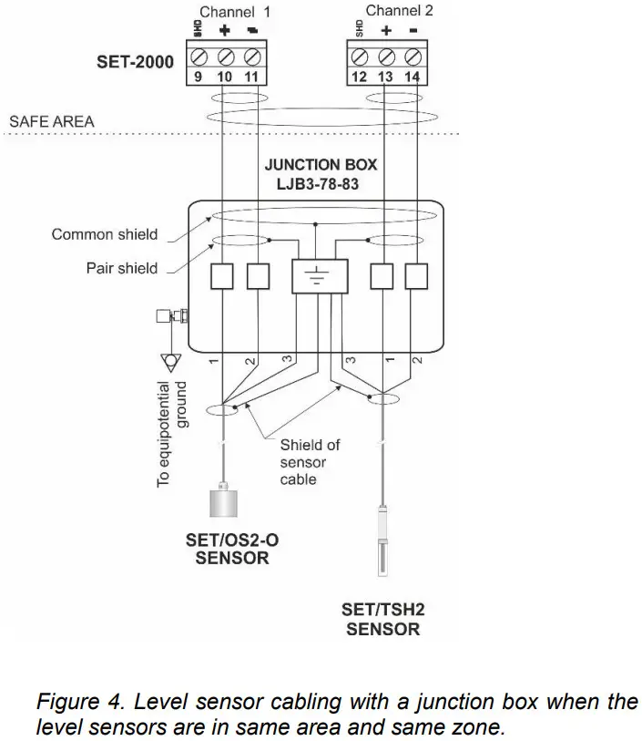
2.1 Cabling when using cable junction box
If the sensor cable must be extended or there is need for equipotential grounding, it can be done with the cable junction box. The cabling between the SET-2000 control unit and the junction box should be done with a shielded twisted pair instrument cable.
LJB2 and LJB3 junction boxes enable cable extension in explosive atmospheres.
In examples in figures 4 and 5 the shields and excess wires have been connected to the same point in galvanic contact with metallic frame of the junction box. This point can be connected to equipotential ground thru the ground terminal. Other components of the system that need to be grounded can also be connected to the same ground terminal.
The wire used for equipotential ground must be min. 2.5 mm² mechanically protected or, when not mechanically protected, the minimum cross section is 4 mm².
Please make sure, that the sensor cables do not exceed the maximum allowed electrical parameters – see appendix 2.
Detailed cabling instructions can be found in the instructions of particular Labkotec SET sensors.
2.1.1 Level sensors in the same area and zone
In the example in figure 4 the level sensors are located in the same area and in the same explosion-hazardous zone. Cabling can be made with one two-pair cable, whereupon both pairs are equipped with their own shields. Make sure, that the signal wires of the cables can never be connected to each other.
2.1.2 Level sensors in different areas and zones
Level sensors in figure 5 are located in separate areas and zones.
Connections must then be made with separate cables. Also the equipotential grounds can be separate.

![]() Junction boxes of types LJB2 and LJB3 include light alloy parts. When installing in explosive atmosphere, make sure, that the junction box is located so, that it can not be mechanically damaged or it will not be exposed to external impacts, friction etc. causing ignition of sparks.
Junction boxes of types LJB2 and LJB3 include light alloy parts. When installing in explosive atmosphere, make sure, that the junction box is located so, that it can not be mechanically damaged or it will not be exposed to external impacts, friction etc. causing ignition of sparks.
Make sure, that the junction is closed properly.
OPERATION AND SETTINGS
The SET-2000 control unit is initialized at the factory as follows. See a more detailed description in chapter 3.1 Operation.
| Channel 1 | Alarm takes place when the level hits the sensor (high level alarm) |
| Channel 2 | Alarm takes place when the level leaves the sensor (low level alarm) |
| Relays 1 ja 2 | Relays de-energize in respective channels’ alarm and fault situations (socalled fail-safe operation). Operational delay is set to 5 seconds. The trigger level is normally at the middle of the sensor’s sensing element. |
3.1 Operation
The operation of a factory-initialized SET-2000 is described in this chapter.
If the operation is not as described here, check the settings and operation (chapter 3.2) or contact a representative of the manufacturer.
| Normal mode – no alarms | The level in the tank is between the two sensors. Mains LED indicator is on. Other LED indicators are off. Relays 1 and 2 are energized. |
| High level alarm | The level has hit the high level sensor (sensor in the medium). Mains LED indicator is on. Sensor 1 Alarm LED indicator is on. Buzzer on after 5 sec delay. Relay 1 de-energizes after 5 sec delay. Relay 2 remains energized. |
| Low level alarm | The level is below low level sensor (sensor in the air) Mains LED indicator is on. Sensor 2 Alarm LED indicator is on. Buzzer on after 5 sec delay. Relay 1 remains energized. Relay 2 de-energizes after 5 sec delay. |
After removal of an alarm, the respective alarm LED indicators and buzzer will be off and respective relay will be energized after 5 sec delay.
| Fault alarm |
A broken sensor, sensor cable break or short circuit, i.e. too low or too high sensor signal current. Mains LED indicator is on. Sensor cable Fault LED indicator is on after 5 sec delay. The relay of respective channel de-energizes after 5 sec delay. Buzzer is on after 5 sec delay. |
| Reset of an alarm | When pressing the Reset push button. Buzzer will go off. Relays will not change their status before the actual alarm or fault is off. |
TEST FUNCTION
Test function provides an artificial alarm, which can be used to test the function of the SET-2000 level switch and the function of otherequipment, which is connected to SET-2000 via its relays.
Attention ! Before pressing Test button, make sure that the change of relay status does not cause hazards elsewhere !
| Normal situation | When pressing the Test push button: Alarm and Fault LED indicators are immediately on. Buzzer is immediately on. Relays de-energize after 2 sec of continuous pressing. When the Test push button is released: LED indicators and buzzer go immediately off. Relays energize immediately. |
| High level or low level alarm on | When pressing the Test push button: Fault LED indicators are immediately on. The Alarm LED indicator of the alarming channel remains on and the respective relay remains de- energised. Alarm LED indicator of the other channel is on and the relay de-energizes. Buzzer remains on. If it has been reset earlier, it will return to be on. When the Test push button is released: The device returns without delay to the preceding status. |
| Fault alarm on | When pressing Test push button: The device does not react with regards to the faulty channel. The device reacts as described above with regards to the functional channel. |
3.2 Altering settings
If the default situation described above does not apply to the site being measured, the following device settings can be changed.
| Operating direction | High level or low level function (increasing or decreasing level). |
| Operational delay | Two alternatives: 5 sec or 30 sec. |
| Trigger level | Trigger point of an alarm in the sensor’s sensing element. |
| Buzzer | The buzzer can be disabled. |
| The following tasks must only be executed by a person with proper education and knowledge of Ex-i devices. We recommend that when altering the settings the mains voltage is off or the device is initialized before the installation is executed. |

The settings are changed using the upper circuit board’s switches (MODE and DELAY) and potentiometer (SENSITIVITY) and the lower circuit board’s jumpers (Sensor selection and Buzzer). The switches are displayed in their default setting in the circuit board figure (figure 6).
OPERATING DIRECTION SETTING (MODE)

Switches S1 and S3 are used to set the operating direction.
When the switch is in its low position Alarm LED indicator as well as buzzer are on and the relay de-energizes when the liquid level is beneath the trigger level of the sensor (low level mode).
This setting is also used, when an alarm of an oil-layer on water is required by using a capacitive Labkotec SET sensor.
When the switch is in its high position the Alarm LED indicator as well as buzzer will be on and the relay deenergizes when the liquid level is above the sensor’s trigger level (high level mode).
OPERATIONAL DELAY SETTING (DELAY)

Switches S2 and S4 are used to set the operational delay of the device. When the switch is in low position relays deenergize and buzzer is on after 5 seconds after the level reaches trigger level, if the level still remains on the same side of the trigger level.
When the switch is in high position, the delay is 30 seconds.
Delays are operational in both directions (energizing, deenergizing) Alarm LEDs follow the sensor current value and trigger level without delay. Fault LED has a fixed 5 sec delay.
TRIGGER LEVEL SETTING (SENSITIVITY)

Trigger level setting is executed as follows:
- Immerse the sensor’s sensing element to the medium to the desired height – see sensor instructions, if needed.
- Rotate the potentiometer so, that the Alarm LED is on and the relay de-energizes – please pay attention to the operational delay.
- Check the function by lifting the sensor to the air and immersing it back to the medium.
TROUBLE-SHOOTING
| Problem: | MAINS LED indicator is off |
| Possible reason: | Supply voltage is too low or the fuse is blown. Transformer or MAINS LED indicator faulty. |
| To do: | 1. Check if the two pole mains switch is off. 2. Check the fuse. 3. Measure the voltage between poles N and L1. It should be 110 VAC ± 10 %. |
| Problem: | FAULT LED indicator is on |
| Possible reason: | Current in sensor circuit too low (cable break) or too high (cable in short circuit). The sensor might also be broken. |
| To do: | 1. Make sure, that the sensor cable has been connected correctly to the SET-2000 control unit. See sensor specific instructions. 2. Measure the voltage separately between the poles 10 and 11 as well as 13 and 14. The voltages should be between 10,3….11,8 V. 3. If the voltages are correct, measure the sensor current one channel at a time. Do as follows: 3.1 Disconnect sensor’s [+] wire from sensor connector (poles 11 and 13). 3.2 Measure short circuit current between [+] and [-] poles. 3.3 Connect mA-meter as in figure 7. Make a comparison to the values in Table 1. More detailed current values are to be found in the instructions of specific sensor’s instructions 3.4. Connect the wire/wires back to respective connector(s). |
If the problems can not be solved with the above instructions, please contact Labkotec Oy’s local distributor or Labkotec Oy’s service.
![]() Attention ! If the sensor is located in an explosive atmosphere, the multimeter must be Exi-approved !
Attention ! If the sensor is located in an explosive atmosphere, the multimeter must be Exi-approved !

Table 1. Sensor currents
| Channel 1 Poles 10 [+] and 11 [-] |
Channel 2 Poles 13 [+] and 14 [-] |
|
| Short circuit | 20 mA – 24 mA | 20 mA – 24 mA |
| Sensor in the air | < 7 mA | < 7 mA |
| Sensor in the liquid (er . 2) |
> 8 mA | > 8 mA |
| Sensor in the water | > 10 mA | > 10 mA |
REPAIR AND SERVICE
The mains fuse (marked 125 mAT) can be changed to another glass tube fuse 5 x 20 mm / 125 mAT complying EN IEC 60127-2/3. Any other repair and service works on the device may be carried out only by a person who has received training in Ex-i devices and is authorized by the manufacturer.
In case of queries, please contact Labkotec Oy’s service.
SAFETY INSTRUCTIONS
![]() SET-2000 level switch must not be installed in explosive atmosphere.
SET-2000 level switch must not be installed in explosive atmosphere.
Sensors connected to it may be installed in explosive atmosphere zone 0, 1 or 2.
In case of installations in explosive atmospheres the national requirements and relevant standards as EN IEC 60079-25 and/or EN IEC 60079-14 must be taken into account.
![]() If electrostatic discharges can cause hazards in the operating environment, the device must be connected into equipotential ground according to requirements with regards to explosive atmospheres.
If electrostatic discharges can cause hazards in the operating environment, the device must be connected into equipotential ground according to requirements with regards to explosive atmospheres.
Equipotential ground is made by connecting all conductive parts into same potential e.g. at the cable junction box. Equipotential ground must be earthed.
The device does not include a mains switch. A two pole mains switch, which isolates both lines (L1, N), must be installed in the main power supply lines in the vicinity of the unit. This switch facilitates maintenance and service operations and it has to be marked to identify the unit.
![]() When executing service, inspection and repair in explosive atmosphere, the rules in standards EN IEC 60079-17 and EN IEC 60079-19 about instructions of Ex-devices must be obeyed.
When executing service, inspection and repair in explosive atmosphere, the rules in standards EN IEC 60079-17 and EN IEC 60079-19 about instructions of Ex-devices must be obeyed.
APPENDICES
Appendix 1 Technical data
| Dimensions | 175 mm x 125 mm x 75 mm (L x H x D) |
| Enclosure | IP 65, material polycarbonate |
| Cable glands | 5 pcs M16 for cable diameter 5-10 mm |
| Operating environment | Temperature: -25 °C…+50 °C Max. elevation above sea level 2,000 m Relative humidity RH 100% Suitable for indoor and outdoor use (protected from direct rain) |
| Supply voltage | 110 VAC ± 10 %, 50/60 Hz Fuse 5 x 20 mm 125 mAT (EN IEC 60127-2/3) The device is not equipped with a mains switch |
| Power consumption | 4 VA |
| Sensors | 2 pcs. of Labkteco SET series sensors |
| Max. resistance of the current loop between the control unit and a sensor | 75 Ω. See more in appendix 2. |
| Relay outputs | Two potential-free relay outputs 250 V, 5 A, 100 VA Operational delay 5 sec or 30 sec. Relays de-energize at trigger point. Operation mode selectable for increasing or decreasing level. |
| Electrical safety | EN IEC 61010-1, Class II POLLUTION DEGREE 2 |
| Insulation level Sensor / Mains supply Channel 1 / Channel 2 |
375V (EN IEC 60079-11) |
| EMC Emission Immunity |
EN IEC 61000-6-3 EN IEC 61000-6-2 |
| Ex-classification Special conditions(X) ATEX IECEx UKEX |
(Ta = -25 °C…+50 °C) EESF 21 ATEX 022X IECEx EESF 21.0015X CML 21UKEX21349X |
| Electrical parameters Characteristic curve of the output voltage is trapezoidal. IIC IIB Attention ! See appendix 2. |
Uo = 14,7 V ,Io = 55 mA ,Po = 297 mW R = 404 Ω Co = 608 nF,Lo = 10 mH,Lo/Ro = 116,5 µH/Ω Co = 3,84 µF ,Lo = 30 mH,Lo/Ro = 466 µH/Ω |
| Manufacturing year: Please see the serial number on the type plate |
xxx x xxxxx xx YY x where YY = manufacturing year (e.g. 22 = 2022) |
Appendix 2 Cabling and electrical parameters
When installing the device, make sure that the electrical values of the cable between SET-2000 and sensors never exceed maximum electrical parameters.
The cabling between SET-2000 control unit and cable extension junction box must be executed as in figures 5 and 6. Extension cable should be shielded paired twisted instrument cable.
Due to non-linear characteristics of the sensor voltage, the interaction of both, capacitance and inductance, must be taken into account. The table below indicates the connecting values in explosion groups IIC and IIB.
In explosion group IIA the values of the group IIB can be followed.
Uo = 14,7 V Io = 55 mA Po = 297 mW R = 404 Ω
The characteristics of the output voltage is trapezoidal.
| Max. permissible value | Both Co and Lo | |||
| Co | Co | Co | Lo | |
| II C | 608nF | 10 mH | 568nF 458 nF 388 nF 328 nF 258 nF |
0,15 mH 0,5 mH 1,0 mH 2,0 mH 5,0 mH |
| II B | 3,84μF | 30 mH | 3,5 µF 3,1 µF 2,4 µF 1,9 µF 1,6 µF |
0,15 mH 0,5 mH 1,0 mH 2,0 mH 5,0 mH |
Lo/Ro = 116,5 :H/![]() (IIC) and 466 :H/
(IIC) and 466 :H/![]() (IIB)
(IIB)
Table 2. Electrical parameters
Maximum length of the sensor cable is determined by the resistance (max. 75 Ω) and other electrical parameters (Co, Lo and Lo/Ro) of the sensor circuit.
| Example: | Determining the maximum cable length Instrument cable with following characteristics is used: – DC resistance of a twin wire at + 20°C is approx. 81 Ω / km. – Inductance is approx. 3 μH / m. – Capacitance is approx. 70 nF/km. |
| Influence of resistance |
Estimate for additional resistances in the circuit is 10 Ω. The max length is (75 Ω – 10 Ω) / (81 Ω / km) = 800 m. The influence of inductance and capacitance of a 800 m cable is: |
| Influence of inductance | Total inductance is 0,8 km x 3 μH/m = 2,4 mH. The sum value of the cable and e.g. SET/OS2 sensor [Li = 30 μH] is 2,43 mH. L/R ratio is thus 2,4 mH / (75 – 10) Ω = 37 μH/Ω, which is less than the maximum allowed value 116,5 μH/Ω. |
| Influence of capacitance | Cable capacitance is 0,8 km x 70 nF/km = 56 nF. Combined value of the cable and the e.g. SET/OS2 sensor [Ci = 3 nF] is 59 nF. When compared to the values in table 2, we can summarize that above values do not limit the use of this particular 800 m cable in explosion groups IIB or IIC. Feasibility of other cable types and sensors for different distances can be calculated accordingly. |
Declaration of conformity
EU DECLARATION OF CONFORMITI
We hereby declare that the product named below has been designed to comply with the relevant requirements of the referenced directives and standards.
| Product | Measuring and control unit SET-1000 and SET-2000 series |
|
| Manufacturer | Labkotec Oy Myllyhaantie 6 FI-33960 Pirkkala Finland |
|
| Directives | The product is in accordance with the following EU Directives | |
| 2014/30/EU 2014/35/EU 2014/34/EU 2011/65/EU |
Electromagnetic Compatibility Directive (EMC) Low Voltage Directive (LVD) Equipment for Potentially Explosive Atmospheres Directive (ATEX) Restriction of Hazardous Substances Directive (RoHS) |
|
| Standards | The foliowing standards were applied: | |
|
|
EMC: | EN IEC 61000-6-2:2019 EN IEC 61000-6-3:2021 EN IEC 61000-3-2:2019 EN 61000-3-3:2013/A1:2019 |
| LVD: | EN 61010-1:2010/A1:2019/AC:2019-04 | |
| ATEX: | EN IEC 60079-0:2018 EN 60079-11:2012 EC-type examination certificate: EESF 21 ATEX 022X. Notified Body: Eurofins Expert Services Ltd, Notified Body number 0537. The revised harmonised standards have been compared to the previous standard versions used in the original type certification and no changes in the “state of the art” apply to the equipment. |
|
| RoHS: | EN IEC 63000:2018 | |
| The product is CE-marked since 2004. | ||
| Signature | This declaration of conformity is issued under the sole responsibility of the manufacturer. Signed for and on behalf of Labkotec Oy. |
|
UK DECLARATION OF CONFORMITY
We hereby declare that the product named below has been designed to comply with the relevant requirements of the referenced regulations and standards.
| Product | Measuring and control unit SET-1000 and SET-2000 series |
|
| Manufacturer | Labkotec Oy Myllyhaantie 6 Fl-33960 Pirkkala Finland |
|
| Regulations | The product is in accordance with the following UK Regulations: | |
| S.1. 2016/1091 S.1. 2016/1107 S.1. 2016/1101 S.1, 2012/3032 |
Electromagnetic Compatibility Regulations Potentially Explosive Atmospheres Regulations Electrical Equipment (Safety) Regulations Electrical and Electronic Equipment Regulations |
|
| Standards | The following designated standards were applied: | |
| EMC: | EN IEC 61000-6-2:2019 EN IEC 61000-6-3:2021 EN IEC 61000-3-2:2019 EN 61000-3-3:2013/A1:2019 |
|
| LVD: | EN 61010-1:2010/A1:2019/AC:2019-04 | |
| ATEX: | EN IEC 60079-0:2018 EN 60079-11:2012 UK-type examination certificate: CML 21UKEX21349x, Approved Body: Eurofins CML, Approved Body number 2503. The revised harmonised standards have been compared to the previous standard versions used in the original type certification and no changes in the “state of the art” apply to the equipment. |
|
| RoHS: | EN 1EC 63000:2018 | |
| The product is UKCA-marked since 2022. | ||
| Signature | This declaration of conformity is issued under the sole responsibility of the manufacturer. Signed for and on behalf of Labkotec Oy. |
|
![]()
Labkotec Oy | Myllyhaantie 6, FI-33960 Pirkkala, Finland
Tel. +358 29 006 260 | [email protected] 0OC001978-EN-0