Contents
KRAMER WP-2UT/R-KIT Transmitter And Signal Receiver
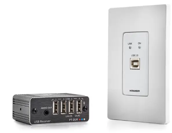
WP-2UT/R-KIT Product Information
Specifications
- USB Transmitter (WP-2UT)
- USB 2.0 Type B Port: Connect to USB host.
- LINK LED: Flashes blue when a link is established.
- ON LED: Lights green when locally powered by the power adapter. Lights orange when powered by PoC.
- Ring Tongue Terminal Grounding Screw: Connect to grounding wire (optional).
- SRV (Tx, Rx), RS-232 (G, Rx, Tx): 5-pin Terminal Block Connector (with a common G pin). Connect for firmware upgrade and serial extension (9600 baud rate).
- Power Supply 2-pin Terminal Block Connector: Connect to the power supply. Connect GND to GND, +12V to +12V.
- LINK POC OUT RJ-45 Connector: Connect to the LINK IN port on the PT-2UR and to power either the device via the receiver or the receiver by the device.
- USB Receiver (PT-2UR)
- LINK LED: Flashes blue when a link is established.
- AUDIO OUT 3.5mm Mini Jack: Connect to an unbalanced stereo audio acceptor.
- USB 2 Type A Ports (1 to 4): Connect to USB devices. Connect PT-2UR directly to the power adapter in order to charge USB devices.
- ON LED: Lights green when locally powered by the power adapter. Lights orange when powered by PoC.
- LINK IN RJ-45 Connector: Connect to the LINK OUT port on the WP-2UT and to power either the device via the transmitter or the transmitter by the device.
- PROG (Tx, Rx), RS-232 (G, Rx, Tx): 5-pin Terminal Block Connector (with a common G pin). Connect for firmware upgrade and serial extension (9600 baud rate).
- 12V DC Power Connector: Connect to the supplied power adapter.
Product Usage Instructions
Step 1: Check what’s in the box
The WP-2UT/R-KIT package includes the following items:
- WP-2UT USB Transmitter
- PT-2UR USB Receiver
- 1 C-USB/AB-6 cable
- 1 Power adapter and cord
- Installation accessories (Frame set and faceplate, 1 Bracket set)
- 1 Quick start guide
Step 2: Get to know your WP-2UT/R-KIT
Familiarize yourself with the features of your WP-2UT/R-KIT.
WP-2UT Features:
- USB 2.0 Type B Port: Connect to USB host.
- LINK LED: Flashes blue when a link is established.
- ON LED: Lights green when locally powered by the power adapter. Lights orange when powered by PoC.
- Ring Tongue Terminal Grounding Screw: Connect to grounding wire (optional).
- SRV (Tx, Rx), RS-232 (G, Rx, Tx): 5-pin Terminal Block Connector (with a common G pin). Connect for firmware upgrade and serial extension (9600 baud rate).
- Power Supply 2-pin Terminal Block Connector: Connect to the power supply. Connect GND to GND, +12V to +12V.
- LINK POC OUT RJ-45 Connector: Connect to the LINK IN port on the PT-2UR and to power either the device via the receiver or the receiver by the device.
PT-2UR Features
- LINK LED: Flashes blue when a link is established.
- AUDIO OUT 3.5mm Mini Jack: Connect to an unbalanced stereo audio acceptor.
- USB 2 Type A Ports (1 to 4): Connect to USB devices. Connect PT-2UR directly to the power adapter in order to charge USB devices.
- ON LED: Lights green when locally powered by the power adapter. Lights orange when powered by PoC.
- LINK IN RJ-45 Connector: Connect to the LINK OUT port on the WP-2UT and to power either the device via the transmitter or the transmitter by the device.
- PROG (Tx, Rx), RS-232 (G, Rx, Tx): 5-pin Terminal Block Connector (with a common G pin). Connect for firmware upgrade and serial extension (9600 baud rate).
- 12V DC Power Connector: Connect to the supplied power adapter.
Step 3: Install the WP-2UT/R-KIT
Follow the instructions below to install the WP-2UT/R-KIT:
WP-2UT Installation:
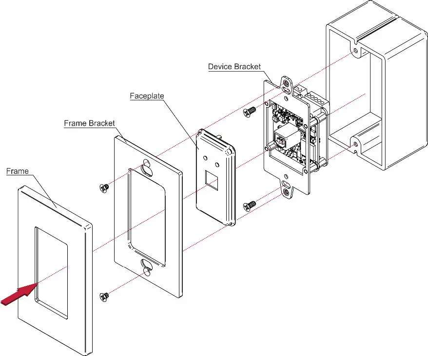
Insert the device into the in-wall box (note that first you need to connect the HDBT cable and power) and connect the parts as shown in the illustrations below:
US-D Version
We recommend that you use any of the following standard 1 Gang in-wall junction boxes (or their equivalent):
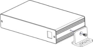
PT-2UR Installation: Install PT-2UR using one of the following methods:
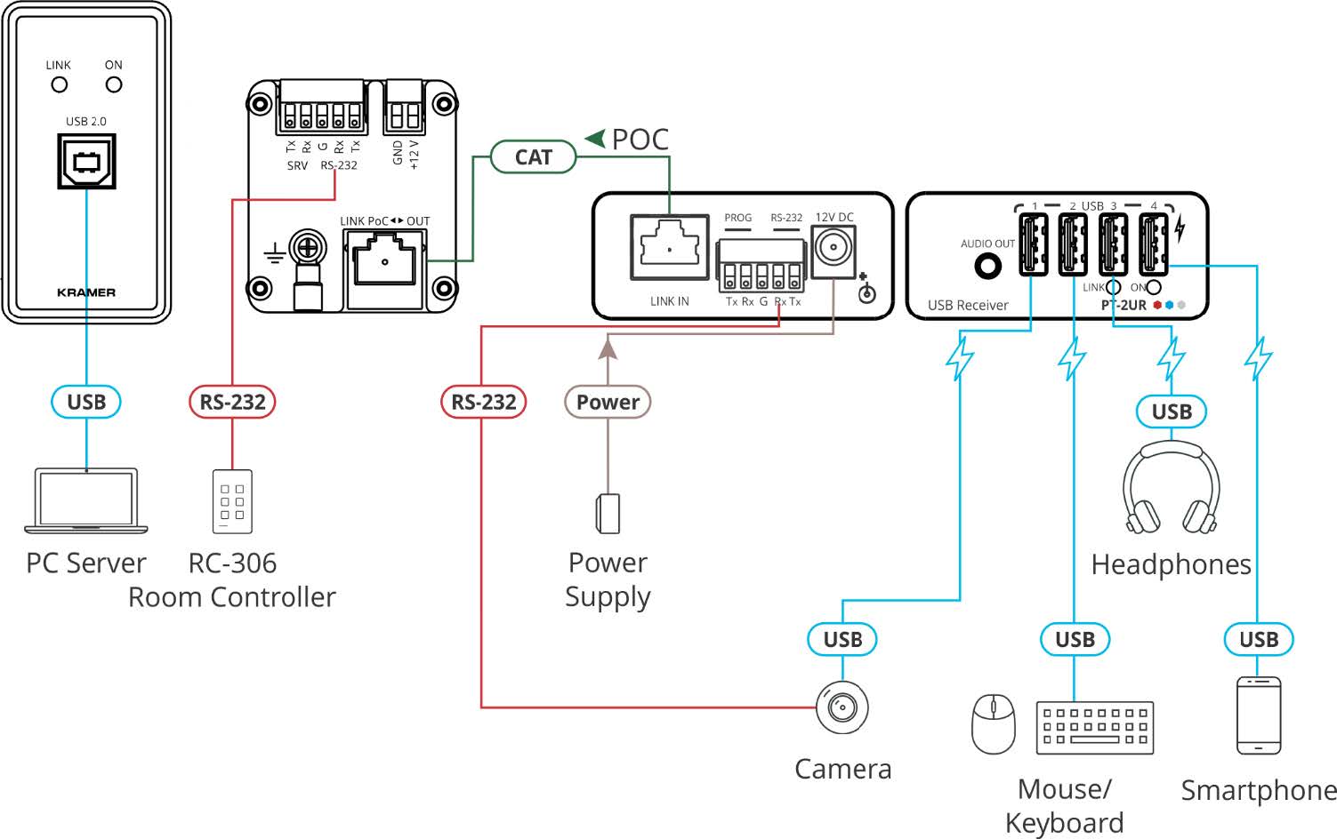
Step 4: Connect the inputs and outputs
- Before connecting any devices to your WP-2UT/R-KIT, make sure to switch OFF the power on each device. For best results, it is recommended to use Kramer high-performance cables to connect AV equipment to the WP-2UT/R-KIT.
- In the following example, devices that are connected to the PT-2UR USB ports are powered/charged while connected. Only 9600 baud rate is supported for RS-232 communication for both WP-2UT and PT-2UR.
Grounding the WP-2UT (Optional)
- Connect the ring tongue terminal to the building grounding point wire (a green-yellow, AWG#18 (0.82mm2) wire, crimped with a proper hand-tool is recommended).
- Insert the M3x6 screw through the toothed lock washers and the tongue terminal in the order shown above.
- Insert the M3x6 screw (with the two toothed lock washers and ring tongue terminal) into the grounding screw hole.
FAQ:
Q: Where can I download the latest user manual and check for firmware upgrades?
A: You can download the latest user manual and check for firmware upgrades by visiting www.kramerav.com/downloads/WP-2UT/R-KIT.
WP-2UT/R-KIT Quick Start Guide
- This guide helps you install and use your WP-2UT/R-KIT for the first time.
- Go to www.kramerav.com/downloads/WP-2UT/R-KIT to download the latest user manual and check if firmware upgrades are available.
Step 1: Check what’s in the box
- WP-2UT USB Transmitter
- PT-2UR USB Receiver
- 1 C-USB/AB-6 cable
- 1 Power adapter and cord
- Installation accessories
- Frame set and faceplate
- 1 Bracket set
- 1 Quick start guide
Step 2: Get to know your WP-2UT/R-KIT
WP-2UT 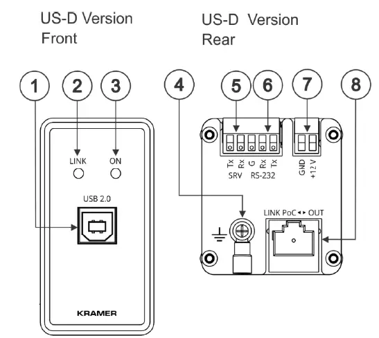
| # | Feature | Function | |
| 1 | USB 2.0 Type B Port | Connect to USB host. | |
| 2 | LINK LED | Flashes blue when a link is established. | |
| 3 | ON LED | Lights green when locally powered by the power adapter. Lights orange when powered by PoC. | |
| 4 | Ring Tongue Terminal Grounding Screw | Connect to grounding wire (optional). | |
| 5 | SRV (Tx, Rx) | 5-pin Terminal Block Connector (with a common G pin) | Connect for firmware upgrade. |
| 6 | RS-232 (G, Rx, Tx) | Connect for serial extension (9600 baud rate). | |
| 7 | Power Supply 2-pin Terminal Block Connector | Connect to the power supply. Connect GND to GND, +12V to +12V. | |
| 8 | LINK POC ◄► OUT RJ-45 Connector | Connect to the LINK IN port on the PT-2UR and to power either the device via the receiver or the receiver by the device. | |
PT-2UR 
| # | Feature | Function | |
| 9 | LINK LED | Flashes blue when a link is established. | |
| 10 | AUDIO OUT 3.5mm Mini Jack | Connect to an unbalanced stereo audio acceptor. | |
| 11 | USB 2 Type A Ports (1 to 4) | Connect to USB devices. Connect PT-2UR directly to the power adapter in order to charge USB devices. | |
| 12 | ON LED | Lights green when locally powered by the power adapter. Lights orange when powered by PoC. | |
| 13 | LINK IN RJ-45 Connector | Connect to the LINK OUT port on the WP-2UT and to power either the device via the transmitter or the transmitter by the device. | |
| 14 | PROG (Tx, Rx) | 5-pin Terminal Block
Connector (with a common G pin) |
Connect for firmware upgrade. |
| 15 | RS-232 (G, Rx, Tx) | Connect for serial extension (9600 baud rate). | |
| 16 | 12V DC Power Connector | Connect to the supplied power adapter. | |
Step 3: Install the WP-2UT/R-KIT
WP-2UT
Insert the device into the in-wall box (note that first you need to connect the HDBT cable and power) and connect the parts as shown in the illustrations below:
US-D Version
- DECORA® design or similar frames are included in US-D models. DECORA® is a registered trademark of Leviton Manufacturing Co., Inc.
- We recommend that you use any of the following standard 1 Gang in-wall junction boxes (or their equivalent):
- US-D: 1 Gang US electrical junction boxes.
PT-2UR
Install PT-2UR using one of the following methods:
- Attach the rubber feet and place the unit on a flat surface.
- Fasten a bracket (included) on each side of the unit and attach it to a flat surface (see www.kramerav.com/downloads/PT-2UT/R ).
- Mount the unit in a rack using the recommended rack adapter (see www.kramerav.com/product/PT-2UT/R).
- Ensure that the environment (e.g., maximum ambient temperature & air flow) is compatible for the device.
- Avoid uneven mechanical loading.
- Appropriate consideration of equipment nameplate ratings should be used for avoiding overloading of the circuits.
- Reliable earthing of rack-mounted equipment should be maintained.
- Maximum mounting height for the device is 2 meters.
Step 4: Connect the inputs and outputs
- Always switch OFF the power on each device before connecting it to your WP-2UT/R-KIT. For best results, we recommend that you always use Kramer high-performance cables to connect AV equipment to the WP-2UT/R-KIT.
- In the following example, devices that are connected to the PT-2UR USB ports are powered/charged while connected.
- Only 9600 baud rate is supported for RS-232 communication for both WP-2UT and PT-2UR.
Grounding the WP-2UT (Optional)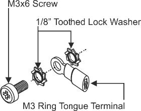
- Connect the ring tongue terminal to the building grounding point wire (a green-yellow, AWG#18 (0.82mm2) wire, crimped with a proper hand-tool is recommended).
- Insert the M3x6 screw through the toothed lock washers and the tongue terminal in the order shown above.
- Insert the M3x6 screw (with the two toothed lock washers and ring tongue terminal) into the grounding screw hole and tighten the screw.
| Wiring the RJ-45 Connectors | |||
| This section defines the TP pinout, using a straight pin-to-pin cable with RJ-45 connectors. | EIA /TIA 568B | 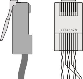 |
|
| PIN | Wire Color | ||
| 1 | Orange / White | ||
| 2 | Orange | ||
| 3 | Green / White | ||
| 4 | Blue | ||
| It is recommended that the cable ground shielding be connected/soldered to the connector shield. | 5 | Blue / White | |
| 6 | Green | ||
| 7 | Brown / White | ||
| 8 | Brown | ||
To achieve specified extension distances, use the recommended Kramer cables available at www.kramerav.com/product/WP-2UT/R-KIT . Using third-party cables may cause damage!
Step 5: Connect the power
Connect the 12V power adapter to the WP-2UT/R-KIT transmitter or receiver side and plug the power supply into the mains electricity.
Safety Instructions
Caution
- For products with relay terminals and GPIO ports, please refer to the permitted rating for an external connection, located next to the terminal or in the User Manual.
- There are no operator serviceable parts inside the unit.
Warning
- Use only the power cord that is supplied with the unit.
- Disconnect the power and unplug the unit from the wall before installing.
- Do not open the unit. High voltages can cause electrical shock! Servicing by qualified personnel only.
- To ensure continuous risk protection, replace fuses only according to the rating specified on the product label which located on the bottom of the unit.