Contents
KNX Gateway Kostal Inverters
Specifications
- Product Name: KNX Gateway for Kostal Inverters
- Model Number: INV-KNX-KO-UM
- Revision: 1.00
- Page: 1 of 17
INTRODUCTION
The KNX gateway for Kostal inverters provides a simple solution to transfer all relevant data from the inverters to KNX.
It allows integrators to take advantage of a fully integrated solar panel inverter, the data can be used to optimize energy consumption, monitoring, trending or to trigger specific action in the KNX installation.
Main features
- KNX Interface for Kostal inverters serie
- Monitoring of Energy, Power, current, voltage, frequency temperature, …
- Connected to the inverter over Ethernet
- Galvanic insulation from the KNX bus
- Configurable refresh rate of inverter data
- DIN rail mounted
- Auxiliary power supply 12-30VDC
- KNX logic module including logic gates, sequences, triggers, math operation and weekly calendar events.
OVERVIEW
USAGE & LIMITATION
This gateway is intended to be used with an Kostal inverter compatible with the SunSpec modbus interface definition. The inverter is connected to the ethernet network on the same router as the KNX gateway.
SOFTWARE
The KNX Interface is configured using the ETS tool, the free ETS Demo version can be downloaded from the website of KNX Association. The free version allows to configure up to 5 KNX modules in a project, the KNX gateway is only one module, all devices can be configured using this version.
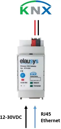
CONNECTION DIAGRAM
- The KNX bus is connected on the top side of the gateway.
- An external power supply 12-30VDC is required and connected on the bottom side of the module, beside the RJ45 connector for the ethernet cable.
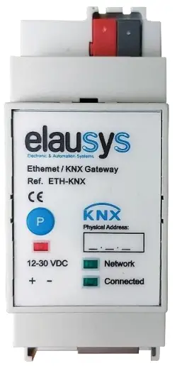
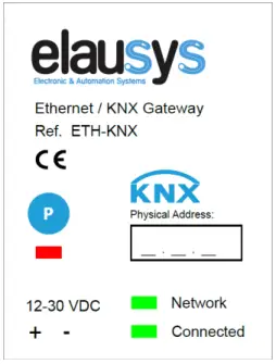
FRONT PANEL
The front panel is equipped with two green status LED:
Network: Physical connection to the ethernet network is established. Connected: Communication with the inverter is established.
- Button “P” : KNX Programming mode button
- Red LED : KNX Programming status LED
PARAMETERS
The KNX interface parameters are defined in the “parameters” tab of the device, in the ETS project.
INVERTER SETTINGS
The following parameters are defined in the inverter settings section of the parameters:
| PARAMETER | VALUES | DESCRIPTION |
| AC Network | § Single phase (default)
§ Tri-Phase |
Type of AC network |
| Number of PV Circuits | § 1 … 4 | Up to 3 PV circuits are available on this inverter model. |
| Inverter model | § 0…255 | 5 = Kostal Inverters |
| Refresh rate (min) | § 0…255 | Cyclic rate of data polling from the inverter. |
| Battery 1 | § Not Used / Used | Display group objects to monitor the status of battery 1 |
| Battery 2 | § Not Used / Used | Display group objects to monitor the status of battery 2 (NOT USED for this inverter) |
| Powermeter | § Not Used / Used | Display group objects to monitor the powermeter value |
| Timezone | § UTC-11… UTC+14 | Timezone where the device is installed. It is used for logic functions based on the weekly calendar. |
| Daylight saving time | § Not Used / Used | Set if daylight saving is used where the device is installed. It is used for logic functions based on the weekly calendar. |
| Device Options | Text string | Device options are not available on this device. |
LOGIC FUNCTIONS
The KNX logic module is a virtual extension module that is part of the ETS application on the inverters gateways. Each logic module includes 8 logic functions including logic gates, sequences, triggers, math operation and weekly calendar events.
- Up to 64 logic functions using extension modules
- Logic Gate with 8 inputs, configurable output delay and inversion
- Sequence with 4 steps, configurable outputs delays and datatypes
- Trigger with inputs logic, delays and weekly calendar events
- Math operations with configurable objects type and delays
Refer to the KNX Logic Module manual for more details on each function.
COMMUNICATION OBJECTS
GENERAL
General communication objects of the device.
| GO | NAME | DESCRIPTION |
|
1 |
Module status |
Sends 0 when the module is operating
normally, sends an error code when applicable. |
| 2 | Firmware version | Returns the firmware version of the device when the object is read. |
INVERTERS OBJECTS
| GO | NAME | DESCRIPTION |
| 3 | AC Current | AC Total Current value |
| 4 | AC Current A | AC Current phase A |
| 5 | AC Current B | AC Current phase B |
| 6 | AC Current C | AC Current phase C |
| 7 | AC Voltage | AC Total Voltage |
| 8 | AC Voltage AB | AC Voltage phase AB (NOT USED) |
| 9 | AC Voltage BC | AC Voltage phase BC (NOT USED) |
| 10 | AC Voltage CA | AC Voltage phase CA (NOT USED) |
| 11 | AC Voltage AN | AC Voltage phase AN |
| 12 | AC Voltage BN | AC Voltage phase BN |
| 13 | AC Voltage CN | AC Voltage phase CN |
| 14 | DC Current | DC Total Current value (NOT USED) |
| 15 | DC Voltage | DC Total Voltage (NOT USED) |
| 16 | PV1 Voltage | PV1 Voltage |
| 17 | PV1 Current | PV1 Current |
| 18 | PV2 Voltage | PV2 Voltage |
| 19 | PV2 Current | PV2 Current |
| 20 | PV3 Voltage | PV3 Voltage |
| 21 | PV3 Current | PV3 Current |
| 22 | PV4 Voltage | PV4 Voltage (NOT USED) |
| 23 | PV4 Current | PV4 Current (NOT USED) |
| 24 | AC Power | AC Power |
| 25 | DC Power | DC Power |
| 26 | AC Frequency | AC Frequency |
| 27 | AC VA | AC Apparent power |
| 28 | AC VAR | AC Reactive power |
| 29 | AC PF | Power factor |
| 30 | AC Energy | Total AC Energy |
| 31 | Efficiency | Inverter efficiency (NOT USED) |
| 32 | Insulation | Insulation resistance |
| 33 | Temperature | Cabinet temperature |
| 40 | Daily Energy Yield | Daily energy |
| 41 | Battery 1 Running Status | (NOT USED) |
| 42 | Battery 1 power | Battery charging/discharging power |
| 43 | Battery 1 SOC | Battery state of charge |
| 44 | Battery 1 current day charge | (NOT USED) |
| 45 | Battery 1 current day discharge | (NOT USED) |
| 46 | Battery 1 total charge | Total battery charge |
| 47 | Battery 1 total discharge | Total battery discharge |
| 48 | Battery 2 Running Status | (NOT USED) |
| 49 | Battery 2 power | (NOT USED) |
| 50 | Battery 2 SOC | (NOT USED) |
| 51 | Battery 2 current day charge | (NOT USED) |
| 52 | Battery 2 current day discharge | (NOT USED) |
| 53 | Battery 2 total charge | (NOT USED) |
| 54 | Battery 2 total discharge | (NOT USED) |
| 55 | Powermeter | > 0: charging
< 0: discharging |
GROUP OBJECT LIST
| GO | Name | Function | Size | Flags | Type ID | Type Name | Description |
| 1 | Module status | Status code | 1 byte | C R – T – | 20.011 | DPT_ErrorClass_System | Device status |
| 2 | Firmware version | Text String | 14 bytes | C R – T – | 16.000 | Character string | Firmware version of the device |
| 3 | AC Current | Actual value | 4 bytes | C R – T – | 14.019 | Electric current (A) | AC Total Current value |
| 4 | AC Current A | Actual value | 4 bytes | C R – T – | 14.019 | Electric current (A) | AC Current phase A |
| 5 | AC Current B | Actual value | 4 bytes | C R – T – | 14.019 | Electric current (A) | AC Current phase B |
| 6 | AC Current C | Actual value | 4 bytes | C R – T – | 14.019 | Electric current (A) | AC Current phase C |
| 7 | AC Voltage | Actual value | 4 bytes | C R – T – | 14.027 | Electric potential (V) | AC Total Voltage |
| 8 | AC Voltage AB | Actual value | 4 bytes | C R – T – | 14.027 | Electric potential (V) | AC Voltage Phase AB value |
| 9 | AC Voltage BC | Actual value | 4 bytes | C R – T – | 14.027 | Electric potential (V) | AC Voltage Phase BC value |
| 10 | AC Voltage CA | Actual value | 4 bytes | C R – T – | 14.027 | Electric potential (V) | AC Voltage Phase CA value |
| 11 | AC Voltage AN | Actual value | 4 bytes | C R – T – | 14.027 | Electric potential (V) | AC Voltage Phase AN value |
| 12 | AC Voltage BN | Actual value | 4 bytes | C R – T – | 14.027 | Electric potential (V) | AC Voltage Phase BN value |
| 13 | AC Voltage CN | Actual value | 4 bytes | C R – T – | 14.027 | Electric potential (V) | AC Voltage Phase CN value |
| 14 | DC Current | Actual value | 4 bytes | C R – T – | 14.019 | Electric current (A) | DC Total Current value |
| 15 | DC Voltage | Actual value | 4 bytes | C R – T – | 14.027 | Electric potential (V) | DC Total Voltage |
| 16 | PV1 Voltage | Actual value | 4 bytes | C R – T – | 14.027 | Electric potential (V) | PV1 Voltage |
| 17 | PV1 Current | Actual value | 4 bytes | C R – T – | 14.019 | Electric current (A) | PV1 Current |
| 18 | PV2 Voltage | Actual value | 4 bytes | C R – T – | 14.027 | Electric potential (V) | PV2 Voltage |
| 19 | PV2 Current | Actual value | 4 bytes | C R – T – | 14.019 | Electric current (A) | PV2 Current |
| 20 | PV3 Voltage | Actual value | 4 bytes | C R – T – | 14.027 | Electric potential (V) | PV3 Voltage |
| 21 | PV3 Current | Actual value | 4 bytes | C R – T – | 14.019 | Electric current (A) | PV3 Current |
| 22 | PV4 Voltage | Actual value | 4 bytes | C R – T – | 14.027 | Electric potential (V) | PV4 Voltage |
| 23 | PV4 Current | Actual value | 4 bytes | C R – T – | 14.019 | Electric current (A) | PV4 Current |
| 24 | AC Power | Actual value | 4 bytes | C R – T – | 14.056 | Power (W) | AC Power |
| 25 | DC Power | Actual value | 4 bytes | C R – T – | 14.056 | Power (W) | DC Power |
| 26 | AC Frequency | Actual value | 4 bytes | C R – T – | 14.033 | Frequency (Hz) | AC Frequency |
| 27 | AC VA | Actual value | 4 bytes | C R – T – | 14.056 | Power (W) | AC Apparent power |
| 28 | AC VAR | Actual value | 4 bytes | C R – T – | 14.056 | Power (W) | AC Reactive power |
| 29 | AC PF | Actual value | 4 bytes | C R – T – | 14.057 | Power factor (cos phi) | Power factor |
| 30 | AC Energy | Actual value | 4 bytes | C R – T – | 13.013 | Active energy (kWh) | Total AC Energy |
| 31 | Efficiency | Actual value | 2 bytes | C R – T – | 8.010 | Percentage (%) | Inverter efficiency |
| 32 | Insulation | Actual value | 4 bytes | C R – T – | 14.056 | Resistance (Ohm) | Insulation resistance |
| 33 | Temperature | Actual value | 2 bytes | C R – T – | 9.001 | Temperature (°C) | Cabinet temperature |
| 40 | Daily Energy Yield | Actual value | 4 bytes | C R – T – | 13.013 | Energy (kWh) | |
| 41 | Battery 1 Running Status | Actual value | 2 bytes | C R – T – | – | – | Status code |
| 42 | Battery 1 power | Actual value | 4 bytes | C R – T – | 14.056 | Power (W) | |
| 43 | Battery 1 SOC | Actual value | 1 byte | C R – T – | 5.001 | Percentage (%) | State of charge (%) |
| 44 | Battery 1 current day charge | Actual value | 4 bytes | C R – T – | 13.013 | Energy (kWh) | |
| 45 | Battery 1 current day discharge | Actual value | 4 bytes | C R – T – | 13.013 | Energy (kWh) | |
| 46 | Battery 1 total charge | Actual value | 4 bytes | C R – T – | 13.013 | Energy (kWh) | |
| 47 | Battery 1 total discharge | Actual value | 4 bytes | C R – T – | 13.013 | Energy (kWh) | |
| 48 | Battery 2 Running Status | Actual value | 2 bytes | C R – T – | – | – | Status code |
| 49 | Battery 2 power | Actual value | 4 bytes | C R – T – | 14.056 | Power (W) | |
| 50 | Battery 2 SOC | Actual value | 1 byte | C R – T – | 5.001 | Percentage (%) | State of charge (%) |
| 51 | Battery 2 current day charge | Actual value | 4 bytes | C R – T – | 13.013 | Energy (kWh) | |
| 52 | Battery 2 current day discharge | Actual value | 4 bytes | C R – T – | 13.013 | Energy (kWh) | |
| 53 | Battery 2 total charge | Actual value | 4 bytes | C R – T – | 13.013 | Energy (kWh) | |
| 54 | Battery 2 total discharge | Actual value | 4 bytes | C R – T – | 13.013 | Energy (kWh) | |
| 55 | Powermeter | Actual value | 4 bytes | C R – T – | 14.056 | Power (W) |
CONFIGURATION
NETWORK CONFIGURATION
By default, the IP address of the KNX gateway is set to 192.168.1.51 Using a laptop connected to the gateway, open a web browser and navigate to the IP address of the gateway.
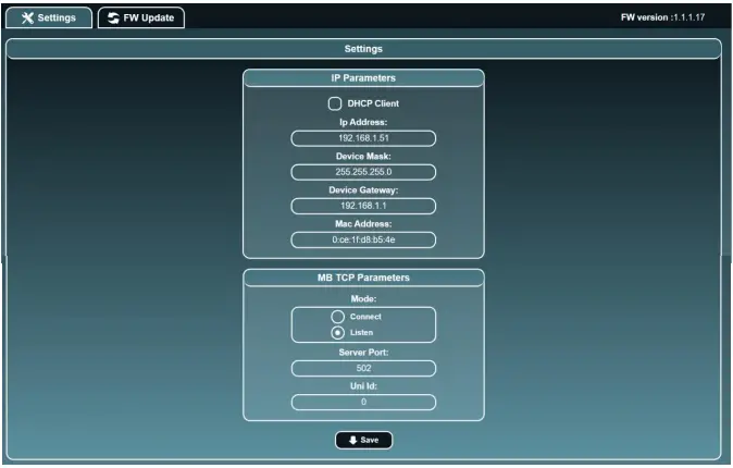
Set a fixed IP address of your choice for the KNX gateway and configure the modbus TCP settings as below:
- Mode : Connect
- IP : IP Address of the inverter
- Server Port : 1502
- Uni Id : 71U
KNX PHYSICAL DEVICE
- ELAUSYS devices are configured using the ETS tool. You should first download and install the free version of ETS tool before you continue.
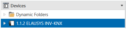
- The INV-KNX Interface must be assigned a physical address on the KNX network. Assign a free address to the module, in our example we choose 1.1.2.
ETS PARAMETERS
Once a KNX physical address is set, open the parameter tab to configure the interface.

- Select the type of AC network (single phase or tri-phase).
- Set the inverter model to 5 for Kostal inverters.
- Choose the refresh rate (min) for the complete set of data.
- Select if a powermeter is available on the inverter.
- Device options should remain empty.
ETS GROUP OBJECTS
A group address (GA) must be assigned to each group object (GO) needed by the application. Open the Group Objects tab of the device and assign a GA to the objects as needed.

When GO and parameters are all configured, download the KNX Interface application to the device. The first download requires to press the programming button on the device to set the device in KNX programming mode then perform a full download.
INVERTER CONFIGURATION
Refer to the inverter manual to enable MODBUS over TCP Support
To setup MODBUS TCP:
- Check that the Modbus TCP is enabled
- Check the port number (default : 1502)
- Check the inverter U-ID (default : 71)
FIRMWARE VERSION
This user manual and related ETS application is valid for firmware versions V2.2.0.0 and above. The firmware version can be read from the gateway webpage using a web browser.
It is displayed on the top right of the page.
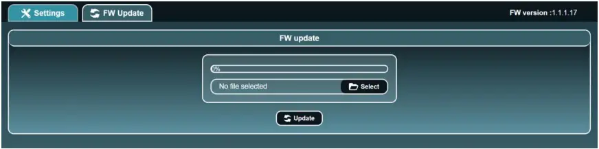
In case an updated firmware would be available, the device can be updated from the FW Update page, the binary file should be selected before pressing the Update button.
DATASHEET
| TECHNICAL DATA | VALUE |
| Auxiliary power supply teminal | Screw terminal 12-30VDC / GND |
| Power consumption KNX bus typ. | < 16 mA @ 29VDC |
| Operating temperature | +5°C to + 45°C |
| Enclosure Dimensions (Space Units) | 2 SU |
| Mounting | DIN RAIL |
| KNX terminal | Pluggable micro terminal, Red/Black, 4 pole PUSH WIRE for solid conductor wire 0.6-0.8 mm² |
| KNX bus voltage | 29 VDC |
© ELAUSYS SPRL
This document cannot be reproduced fully or partially without written authorization