Contents
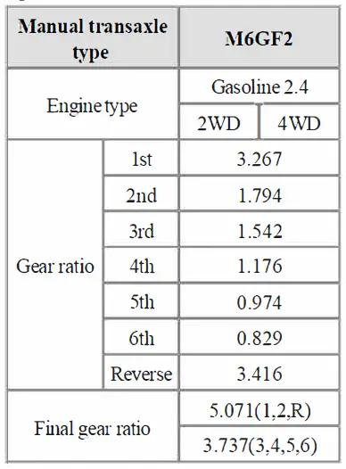
KIA M6GF2 Sportage Transaxle System

Specifications
Tightening Torgues
| Item | N.m | kgf.m | lb-ft |
| Oil drain plug bolt | 58.9~78.5 | 6.0~8.0 | 43.4~57.9 |
| Oil filler plug bolt | 29.4~34.3 | 3.0~3.5 | 21.7~25.3 |
| Shift lever assembly bolt | 8.8~13.7 | 0.9~1.4 | 6.5~10.1 |
| Back up lamp switch | 29.4~34.3 | 3.0 ~ 3.5 | 21.7~25.3 |
| Transaxle mounting bracket 88.3~107.9 9.0~11.0 65.1~79.6 bolt Strut motor installation bolt 42.2~53.9 4.3~5.5 31.1~39.8 Transaxle upper mounting bolt 42.2~53.9 4.3~5.5 31.1~39.8 (TM=>ENG) Transaxle lower mounting bolt 42.2~48.l 4.3~4.9 31.1~35.4 (ENG=>TM) 42.2~53.9 4.3~5.5 31.1~39.8 |
|||
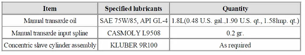
Lubricants
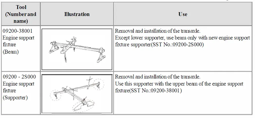
Special Service Tools
Repair procedures
Inspection
Manual transaxle oil Inspection
- Park the vehicle on a level ground and stop the engine.
- Retighten the oil filler plug(A) with a new washer.
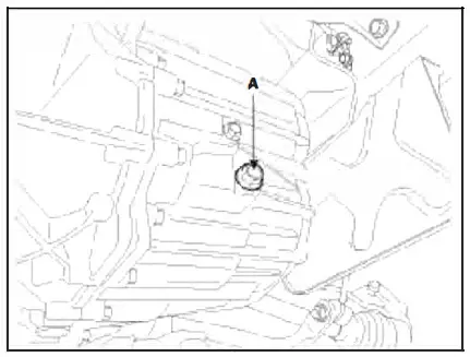
- Check level with finger.
Note: Oil level must be up to fill the hole, if not, add oil until it mns over.
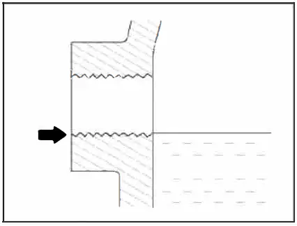
- Retighten the oil filler plug(A) with a new washer.
Tightening torque : 29.4~34.3N.m (3.0~3.5kgf.m, 21.7~25.3lb-ft)
Manual transaxle oil replacement
- Park the vehicle on a level ground and stop the engine.
- Drain the manual oil after loosening the drain plug (A).

- Install the drain plug with new gasket.
Tightening torque : 58.9~78.5N.m (6.0~8.0kgf.m, 43.4~57.9lb-ft) - Add new oil through the filler plug hole and, fill it just below the plug opening. Standard oil: SAE 75W/85, API GL-4
Oil capacity: 1.8L(0.48 U.S. gal.,1.90 U.S. qt., 1.58hnp. qt.)
Components and Components Location
Components
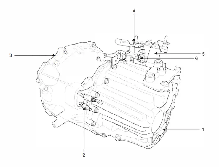
- Manual transaxle case
- Concentric slave cylinder
- Clutch housing
- Shift. cable bracket assembly
- Conol complete shaft
- Back-up lamp switch
Removal
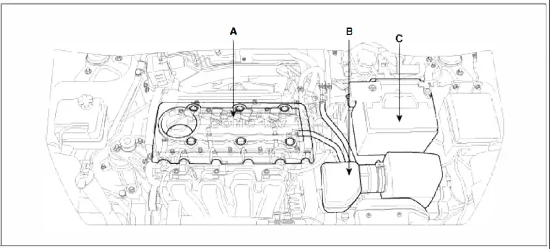
- Remove the following items;
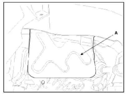
- Engine cover (A). (Refer to “Intake and Exhaust system” in EM group.)
- Air cleaner assembly and air duct(B) . (Refer to “Intake and Exhaust system” in EM group.)
- Batte1y and batte1y tray (C). (Refer to “Charging system” in EE group.)

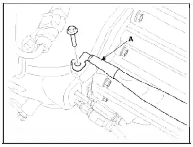
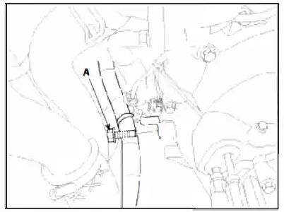
- Remove the ground (A) .
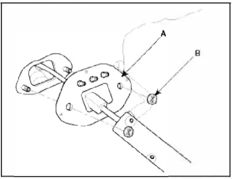
- Disconnect the cable assembly (A) after removing the clips (B) and pins (C).
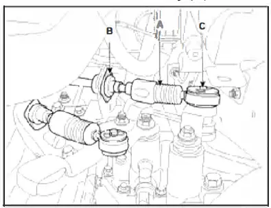
- Disconnect the concentric slave cylinder tube(A) after removing the pins(B).

- Remove the wiring bracket bolt (A).
- Remove the cowl top cover or wiper motor. (Refer to “Windshield Wiper/Washer” in BE group.)
- Remove the cowl complete assembly panel(A).

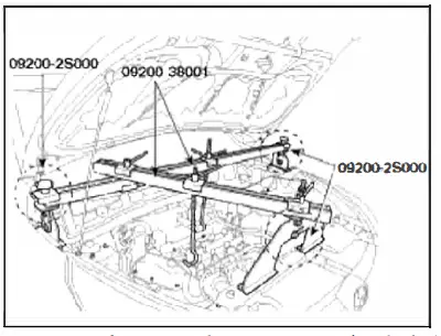
- Using the engine supp01t fixture (Supp01t SST No.: 09200-2S000, Beam SST No.: 09200-38001), hold the engine
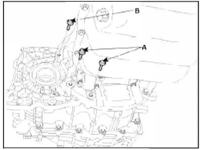
- Remove the transaxle upper mounting bolt (A-2ea) and the start motor mounting bolt (B-2ea).
Tightening torque: 42.2~53.9N.m (4.3~5.5kgf.m, 31.1~39.8lb-ft)
- Supp01ting the transaxle with a jack, remove the mounting bolts(A).
Tightening torque : 88.3~ 107.9N.m (9.0~ 11.0kgf.m, 65.1~ 79.6lb-ft)

- Remove the under cover (A).
Tightening torque: 19.6-21.6N.m (2.0~2.2kgf.m, 14.5~15.9lb-ft)

- Remove the side cover(A).
- Remove the roll rod bracket(C) after removing bolt(A,B).
Tightening torque :- (B) 49.0~63.7N.m (5.0~6.5kgf.m, 36.2~47.0lb-ft)
- (D) 107.9~127.5N.m (11~13kgf.m, 79.6~94.llb-ft)
- Remove the following items;
- Drive shaft assembly. (Refer to “Drive shaft assembly” in DS group.)
- Sub frame assembly. (Refer to “Front suspension system” in SS group)
- In the case of 4WD vehicle, remove the transfer assembly. (Refer to “Transfer assembly” in WD group)
In the case of 2WD vehicle, not remove the transfer assembly.

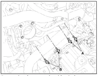
- Remove the mounting bolts(A-4ea, B-2ea) of lower pait of the transaxle, ai1d the left side cover and remove the transaxle assembly by suppo1ting it with a jack.
Tightening torque:- 42.2~48.1 N.m (4.3~4.9kgf.m, 31.1~35.4lb-ft)
- 42.2~53.9 N.m ( 4.3~5.5kgf.m, 31.1 ~39.8lb-ft)

Installation
Installation is the reverse of removal.
- Adding Manual transaxle fluid. (Refer to “Manual transaxle system” in this group.)
- Perform bleeding air procedure in concentric slave cylinder after pouring the brake fluid.(Refer to “Concentric slave cylinder” in CH group.)
Manual Transaxle System > Manual Transaxle Control System> Back-up Lamp Switch> Description and Operation
Description
Back up lamp switch is pushed by the reverse lug sliding when select arm, ar1d switches the back up lamp.
Back-up Lamp Switch > Specifications Specifications
- Working voltage: DC 10~15V
- Operating force : 3.0kg Max.
- Voltage drop: – 0.4V
- Working temperature: -30°C ~ 100°C [-30°F ~ 212°F]
Back-up Lamp Switch > Repair procedures
Inspection
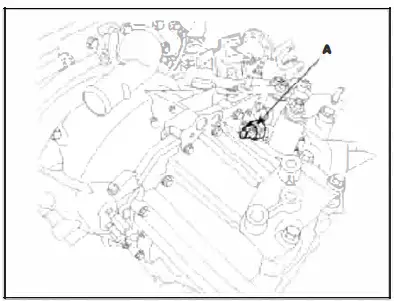
- Disconnect the back up larnp switch connector(A).

- Check the continuity between no. 1 and 2 terminals of backup larnp switch. When the shift lever is in reverse, there should be continuity.
- If necessaiy, repair or replace the backup lainp switch.

Replacement
- Disconnect the back up lamp switch connector(A).

- Remove the back up lamp switch (A).
- Replace a new one and install the back up lamp switch.
Tightening torque : 29.4~34.3N.m (3.0~3.5kgf.m, 21.7~25.3lb-ft)
Shift Lever> Components and Components Location
Components

- Shift lever knob & boot assembly
- Shift lever assembly
- Shift cable assembly
- Select cable assembly
- Retainer
Shift Lever> Repair procedures
Removal
Shift Lever Assembly Replacement
- Remove the floor Interior console assembly. (Refer to “Interior(Console)” in BD group)
- Remove the select cable snap pin (A) and the clip (B) from the select cable assembly.

- Remove the clip (A) from the shift cable assembly.
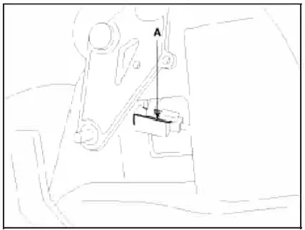
- Remove the shift lever assembly(B) after removing shift lever assembly installation bolt(A).
Tightening torque : 8.8~13.7N.m (0.9~1.4kgf.m, 6.5~10.llb-ft)

- Installation is the reverse of removal.
Make sure vehicle does not roll before setting room side shift lever and T /M side manual control lever to ”N” position.
Shift Cable Replacement
- Remove the floor Interior console assembly. (Refer to “Interior(Console)” in BD group)
- Remove the select cable snap pin (A) and the clip (B) from the select cable assembly.

- Remove the clip (A) from the shift cable assembly.

Tightening torque : 8~1 l.8N.m (0.8-1.2kgf.m, 5.8~8.7lb-ft)
- Remove the cable(B) from the cable bracket(A) at manual transaxle assembly side.
- Remove the pins(C).
- Remove the shift cable and select cable at cabin room.
- Installation is the reverse of removal.
 Make sure vehicle does not roll before setting room side shift lever and TIM side manual control lever to ”N” position.
Inspection
- Check the select cable for proper operation and for damage.
- Check the shift cable for proper operation and for damage.
- Check the boots for damage.
- Check the boots for wear abrasion sticking, restricted movement or damage.
- Check for the weak or damaged spring.
Adjustment
- Install the guide member (A) of the select cable (B).

- Adjust the slide clip (B) to fit it into the select lever pin (A) and install the snap pin (C).

- Remove neutral position pin (A) after shift lever assembly.

C:Usersej20DesktopuploadHTMLSp01tage 20132.4LManual Transaxle System (M6GF2).mht 2012-06-21