 GK-1e Computer Sockets
User Manual
GK1e Computer Sockets
The manual concerns the following types of sockets:
| Series | Symbol of the product |
| DECO | DGK-1e, DGK-3, DGK-5, DGK-2, DGK-4, DGK-6, DGTK |
| ICON | IGK-1e, IGK-3, IGK-5, IGK-2, IGK-4, IGK-6, IGTK |
| MINI | MGK-1e, MGK-3, MGK-5, MGK-2, MGK-4, MGK-6, MGTK |
| FLEXI | FGK-1e, FGK-3, FGK-5, FGK-2, FGK-4, FGK-6, FGTK |
| TREND | GK-1e, GK-3, GK-5, GK-2, GK-4, GK-6, GTK |
| LOGO | LGK-2 |
Assembly manual on the example of the screen socket RJ45 (when it comes to a non-screen socket proceed in the same manner):
- Prise the clasps from both sides and open the module (Photo no. 1).
- Remove the plastic cap with markings of the ways of assembly: A or B (Photo no. 2).
- Strip insulation of the wire and leave 1 cm screen (Photo no. 3).
- Lead the stripped wire through the plastic cap, leaving screen (Photo no. 4).
- Pull the cords of the wire through notches of the plastic cap, keeping suitable colour of the chosen connection standard A or B (Photo no. 5).
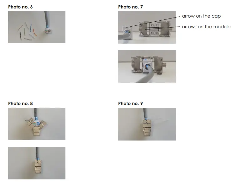
- Cut the projecting ends of the cords (Photo no. 6).
- Insert the plastic cap into the module following the arrows directions both on the cap and on the module (Photo no. 7).
- Close the module. This way the cap shall be pressed automatically (Photo no. 8).
- Press the screen of the wire to the module casing with the cable tie and block it (Photo no. 9).
Photo no.1

NOTE!
Assembly shall be held by a suitably qualified person with deactivated voltage and shall meet the national safety standards
tel. +48 61 437 34 00 I
e-mail: [email protected]
www.karlik.pl