![]() Elite
Elite
Simple Installation Guide
Complete 8/248 input security & control kit 
Contents
Options & Accessories
| EliteCloud APP wwwelitecloud.co.nz |
|
| Monitoring Ethernet or optional PSTN |
|
| Long Range Wireless infinity series | |
| Dashboard (coming soon) |
|
| Integrated Access Control Up to 32 doors |
|
 |
EliteCloud Information Videos Information E® https://www.youtube.com/@elitecontrol2102 https://elitecloud.co.nz/ |
EC-PCB Specifications (Al lines marked * require extra hardware)
| Specification | Description | |
| Ethernet ‘ | Supports smartphone app, local web browser, monitoring to central station & cloud dashboard (coming soon) | |
| smartphone App | Compatible with EliteCloud smartphone a pp for Apple &Android devices. | |
| management | EliteCloud programming &management dashboard coming soon – elitecloud.co.nz | |
| Web Browser | Local web browser programming for configuration without internet. | |
| Inputs – Wired | 8 (onboard), expandable up to 248 with modular EC-Z8 input expanders. | |
| Inputs – Wireless | Supports ‘infinity motion’ PIR detectors Wor ‘infinity input’ reed switches. | |
| Wireless – Hardware | Supports wireless infinity link, motion, remote, input, output, panic &siren. | |
| Outputs – Wired | 6 (onboard). expandable up to 32 with modular EC-04 output expanders. | |
| Accessory Power | 13.8VDC lA fused. | |
| Outputs – 1 & 2 | Monitored 12Voutputs designed for hardwired external & internal sirens | |
| Output-Relay | Output 4 is a clean relay wntact designed for garage doors & gates, | |
| Outputs – Wireless | Supports up to 32 x ‘infinity output’ wireless relay modules | |
| Keypads – Max | Supports up to 32 x Alarm 8/or access control keypad/readers | |
| Keypad – Bus | High speed EliteControl bus | |
| Alarm Keypad Options | EC-KP, EC-TOUCH, EC-LCD& EC-LCD PROX | |
| Keypads/Readers | PW WIEGAND, PW WIEGAND NK PW WIEGAND SKI, PW WIEGAND SK4 & more. | |
| Areas/Partitions | 32 Partitions, each with a dedicated stay/night arm. | |
| Schedules | 52 time schedules for automatic operations or restrictions | |
| Users – Codes | 7000 user codes for alarm or access control functions | |
| Users – Wireless | Up to 1900 – Wireless users/remote buttons are added from users101 to 2000. | |
| PSTN Dialler | Available with additional plug in PSTN dialler module. | |
| Battery Back Up | Dynamic battery monitoring with low vokage disconnect. | |
 |
Battery Charging | 250mA current limited SLA battery charging with over current protection. |
| Power Supply | Built in 13.8V, 1.5A switch mode power supply. | |
 |
Tamper | 2K2 EOL or zero resistance to ground (programmable). |
 |
Keyswitch | Supports up to 248 keyswitch inputs Each takes up 1 of the 248 available inputs |
 |
Update Config ° | Available via EliteCloud dashboard (coming soon) or inbuik web browser. |
 |
Backup Config – | Available via EliteCloud dashboard (coming soon) or inbuilt web browser. |
|
Firmware Update* | Available via EliteCloud dashboard (coming soon) or inbuilt web browser. |
EC-PCB Control Panel Overview
 Important
All’EC” & infinity series products are to be installed by a ‘Skilled person’ and must have training or experience in this equipment technology. A skilled person is expected to use their training or experience to identify energy sources that may cause pain or injury and take appropriate action to prevent unintentional harm to themselves & others

 Bus Support
- Max Cable Length (0.44mm 4 core Security Cable) – 300m maximum combined bus length
- Alarm Keypad Support – EC-KP, EC-TOUCH, EC-LCD & EC-LCD PROX
- Wireless Support – 1 x ‘infinity link’ required to support full infinity wireless product range.
- Expander Support – EC-O4, EC-Z8 & EC-A2
- Access Control Modules – EC-A2 & WIEGAND MINI
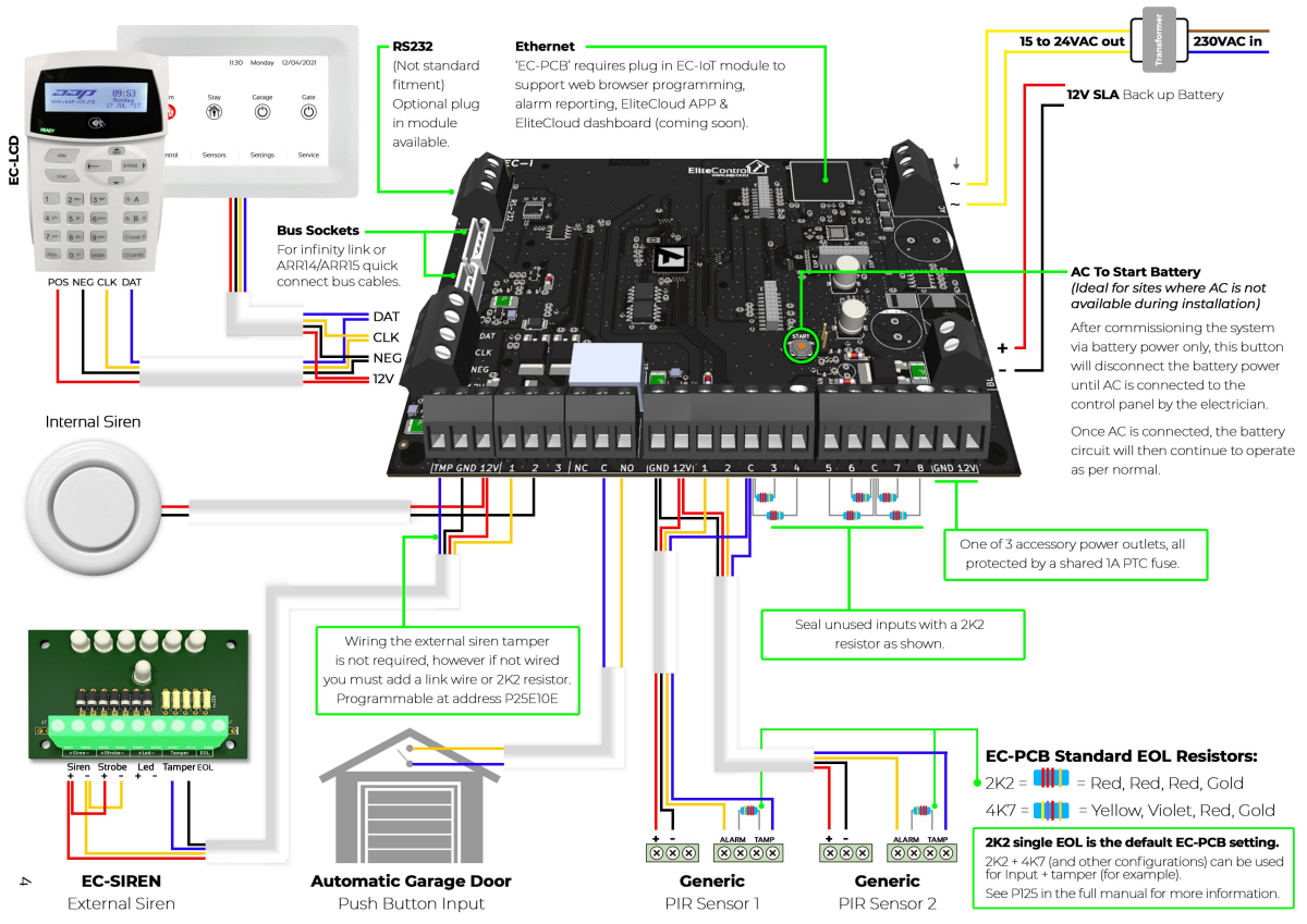
EC-PCB Hardware Connection Overview
![]() EC-PCB Built in Web Browser (requires optional ‘EC-loT’ Ethernet module)
EC-PCB Built in Web Browser (requires optional ‘EC-loT’ Ethernet module)
Web browser is the best way to program the control panel for installations where internet is not available.
![]() Security for Off Site/Remote Connection
Security for Off Site/Remote Connection
It is not recommended to port forward the built in web browser for off site configuration as this is not secure & the system could easily be compromised. Use the EliteCloud dashboard for off site access with any EC-PCB, EC-i, ESL, ESL-2 or Runner control panel. EliteCloud provides a secure end to end encrypted connection from almost anywhere.
![]() Default IP Address
Default IP Address
- 1921681100 is the default IP address for the control panel, however DHCP is on by default so this will change if plugged into a router/switch.
 Retrieving IP Address
- You can view/retrieve the control panel IP address by pressing and holding the ‘9’ button on the ‘EC-LCD’, ‘EC-LCD PROX or ‘EC-KP’ keypads OR by pressing ‘TCP/IP Address’ within the service menu on the ‘EC-TOUCH’ screen.
Connecting
- Once you know the current system IP address you can connect directly to the built in web browser with a patch cable by setting your computer IPV4 to the same range as the control panel.
- Alternatively you can set your computer IPV4 to DHCP/Automatic and connect through a router or switch.
- Once one of the 2 steps above are complete, open your computer web browser and enter the IP address followed by enter to confirm & the ‘Log in’ page shown below should appear.

![]() Signing In
Signing In
- Users from 1to 32 can be used to sign into the web browser. For this you will require the user name & code as programmed into the control panel.
- For example: Default ‘User 1′ name & password is: Name: User 1 Password: 123
- Enter the correct user name & password into the login fields and you will be directed to the ‘Status & Control’ page as detailed below:

Simple Programming
![]() Entering Installer mode
Entering Installer mode
EC-LCD & EC-LCD PROX
Press ‘PROG’ followed by your installer code (default – 000000), then press ‘ENTER’. You should now see ‘Installer: Users’ on the keypad display.
EC-TOUCH
Press ‘Settings, followed by your installer code (default – 000000), then press the tick icon to confirm. You should now see ‘Installer Settings Menu.
 Exiting Installer Mode
EC-LCD & EC-LCD PROX – Press ‘PROG’ (once or twice) until you see ‘<ENTER> to exit’. Then press the ‘ENTER’ button.
EC-TOUCH – Press the back button <” until you return to the home screen.
![]() Changing/Adding User Codes
Changing/Adding User Codes
- To change user codes you must be in ‘Installer mode’ or ‘Client Mode’.
- The EC-PCB panel has the ability to store up to 2000 user codes.
- User codes can be anywhere from 1to 6 digits long & require the ‘ENTER’ button to be pressed after code entry.
- User codes are programmed at Address 1 & then entered into slots from 1to 2000 as detailed below:
Press ‘PROG’1’ENTER’ then the slot you wish to change ie. T, then press ‘ENTER. The keypad will flash back or display the current code (default code is 123). Now enter your new code le. 4 5 6 then press ‘ENTER to confirm.
The new code (456 for example) will flash back or display on the screen.
Below are some examples of adding user codes where ‘P’ represents ‘PROG’ & ‘E’ represents ‘ENTER’.

![]() Changing Installer code
Changing Installer code
There is only one installer code which can only be used when the system is disarmed. To change the installer code simply enter installer mode, then press ‘PROG’ 25 ‘ENTER’ T’ENTER’ and the current code will be displayed. Now enter your new installer code from 1-6 digits and press ‘ENTER’ to confirm
 Changing Entry delays
This is how long a sensor gives you to get in and disarm the system after it has been triggered. Each sensor has its own delay from O to 9999 seconds. If you have to pass a sensor to get to the keypad then it must have an entry delay. In installer mode press ‘PROG’ 144 ‘ENTER’ then select the input you wish to change (1 to 248) and press ‘ENTER.
Now enter the new time (0O to 9999) in seconds and press ‘ENTER’. The new entry delay time should display on the screen
 Changing Exit delay
This is how long you have to get out of the premises after pressing an ‘Arm’ button. This time is programmable from 0to 255 seconds. In installer mode, press ‘PROG’ ‘60″ ‘ENTER’ T ‘ENTER’, now enter the selected time from 0-255 seconds, followed by the ‘ENTER’ button to confirm

Changing Time, Day & Date
Enter installer Mode
Time
P26 E1E (24hr Time) E
Day
P26E2E (Day) E
– Sunday=1,Monday =2, Tuesday =3, Wednesday = 4, Thursday =5, Friday = 6, Saturday =7
Date
P26E3E (Date) E
– DDMMAVY
System Test
When the programming configuration is complete, a quick test is required to confirm all hardware and software is working correctly. Run through the steps below to make sure the system is operating as required.
Make sure no one is moving around the premises as this could affect the test.
- The keypad should not have any input lights on. If input lights are present, make sure:
– Your wiring is correct as per page 4.
– The resistors in the sensors are correct – RED,RED, RED, GOLD (unless using non default EOL configuration).
– You have used the 2K2 resistors provided to seal any unused inputs (or turned them off in programming)
– That all covers are correctly placed on sensors. - Sensors Walk Test
– Enter install mode (as per page 6) then press P 200 E 6 E E to enter walk test mode & the keypad should start beeping. Now walk in front of each sensor and when you get back to the keypad the inputs that are working correctly will permanently display on the keypad. If some sensors are not working, do the following:
– Check your wiring is correct as per page 4.
– Check the resistors in the sensors are correct – RED, RED, RED, GOLD (unless using non default EOL configuration)
– That all covers are correctly placed on sensors. - Test all of the user codes
– Start by typing in user code 1followed by the ENTER’ button and the keypad should start beeping as it arms.
– Now type user code 1in again, followed by the ‘ENTER’ button and the keypad should go quiet as it disarms.
Repeat this test for all of the user codes you have programmed
– Are all user codes operating correctly? If not, please revisit ‘Changing/Adding User Codes’ on the previous page. - Press the ARM button to see if there is enough time to get out of the house before the exit delay beeps stop – If not you will need to extend the exit delay as per ‘Changing Exit Delay’ the previous page.
- Now with the system armed, see if you can get back inside to the keypad and disarm the alarm before the sirens go off
– If not you will need to increase the entry delay time/times as per ‘Changing Entry Delays’ on the previous page. - Make sure the sirens and strobe go off after the entry delay expires
– Arm the system, wait for the beeps to stop then move in front of a sensor. The keypad should start beeping again and as soon as the entry delay is finished the sirens and strobe should go off. Once the sirens have been checked, enter an active user code followed by the ENTER button to disarm the system.
– Does the external siren & strobe operate when the system is in alarm? If not, recheck wiring as per page 4.
– Does the internal siren work? If not, recheck wiring as per page 4.
Reference Material
Program Summary Guide  |
E! Access Control Manual  |
User Manual |
PowerPoint Training Presentation |
| www.aap.co.nz/summary | www.aap.co.nzfaccess | www.aap.co.nz/user | www.aap.co.nz/training |
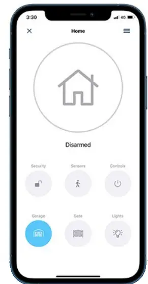
EliteCloud Smartphone APP (requires ‘EC-loT’ Ethernet module)
Important Information
- The APP is ‘Keypad address 8’ on the EC-PCB control panel. L.e. APP functions such as Arm/Disarm & output control need to be mapped or programmed as Keypad 8.
- Arming/Disarming areas from the APP is directly related to User codes/permissions. l.e. Each area that you wish to Arm/Disarm independently from the APP needs it’s own User code.
- Each user must have their own EliteCloud account. Le. You can not use the same email across 2 different Users/Smartphones.
App & Site Setup
It is recommended to test each site on your own smart device before giving ownership to the site owner. See steps below for ‘Adding Users’ & ‘Transferring Ownership’.
Download the EliteCloud App
Search EliteCloud on your smart device store, OR scan the QR code below:

 Sign Up, Sign In & Select a Plan
Open the EliteCloud app, press ‘Sign Up’ & follow the prompts. This process will ask you to register, verify your email, ‘Sign In’ & select a plan.
If you already have an EliteCloud account, simply open the app, ‘Sign In’ & move on to the next step.
 Adding a Site – Each site can only be added/owned by 1 User.
After pressing ‘Add Site’ & accepting the T & C, a QR scanner will appear. Use this to scan the QR code found on your ‘EC-PCB’ control panel. Site ID (MAC & Serial) can also be manually added using the ‘Enter manually’ button.
Scan the QR code for a step by step video on how to add a site.
 Adding & Inviting Users – All users must have their own EliteCloud account. See step 2
Go to the ‘Users’ list found in the main app menu, then press the ‘Invite User’ icon. Next you can scan the new users ‘Account QR Code’ found in their ‘User Settings’ or manually enter their EliteCloud registered email address.
Scan the QR code for a step by step video on how to invite & manage users.

 Accepting Invitations & Transferring Ownership
New users must accept any site invitations from within the ‘Envelope’ icon found at the top left of the sites screen. Once accepted the ‘Owner’ of the site can transfer ownership from within the ‘Users’ list found in the main menu.
Scan this QR code for a step by step video on accepting site invitations
 Monitoring
IP monitoring via the EC-PCB is configured directly from the EliteCloud app.
This is accessed from within ‘Settings’ > ‘Advanced Settings’ > ‘Monitoring Configuration”
EliteCloud Tutorials
Scan the QR code below to view our EliteCloud & EliteControl tutorial videos.

https://www.youtube.com/channel/UCYhukSNdB3GZb-XIoiB6qyg
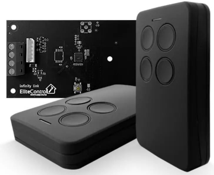
Wireless Remotes (Optional Accessory)
Remotes & other wireless devices can be added to the EC- PLAS with the additional ‘infinity link’ transceiver module as detailed below:
Hardware Connection
Connect the infinity link to the EC-PCB using the ARRI14 bus loom provided with the infinity link.
Alternatively, connect the infinity link to the EC-PCB 12V, NEG, CLK, DAT screw down terminals.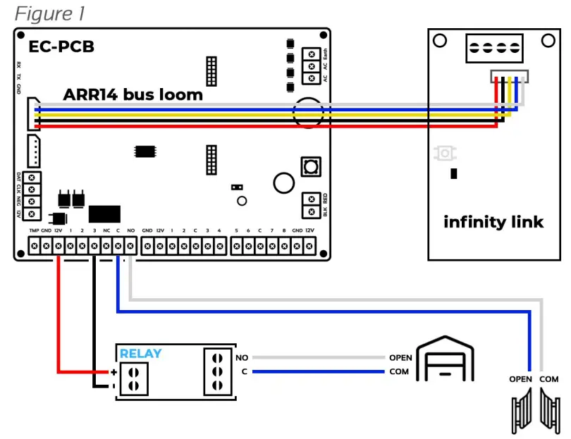 Garage Doors & Gates
Outputs 3 & 4 on the EC-PCB can be wired to garage doors or gates & controlled by remotes, keypads or the EliteCloud app.
Output 4 is a clean contact so can generally be wired directly, however output 3 may require a separate relay as shown in ‘Figure 1″
Output Expansion
The EC-PCB supports a maximum of 32 outputs.
These can be hardwired, wireless or a mixture of both as detailed below:
Hardwired – EC-O4
The EC-O4 is a 4 x relay output expander module that plugs into the EC-PCB bus. Scan QR to find out more:
https://www.aap.co.nz/shop/Alarm+Systems/Accessories/EC-O4.html
Wireless – infinity output
The ‘infinity output’ can be learnt into any of the 32 x EC-PCB outputs for controlling doors, gates & more. Scan QR to find out more:

infinity series
powered by EliteControl
 It is recommended to default each wireless device before learning into a new system.
infinity remote Default Procedure
Press & hold button 1 (shown in ‘Figure 2′) & the LED will display solid red
As soon as the solid red LED turns off, keep holding button 1Twhile pressing button 2, then 4, then 3 in quick succession
After pressing the last button (button 3), a green LED should display to confirm that the default has completed successfully.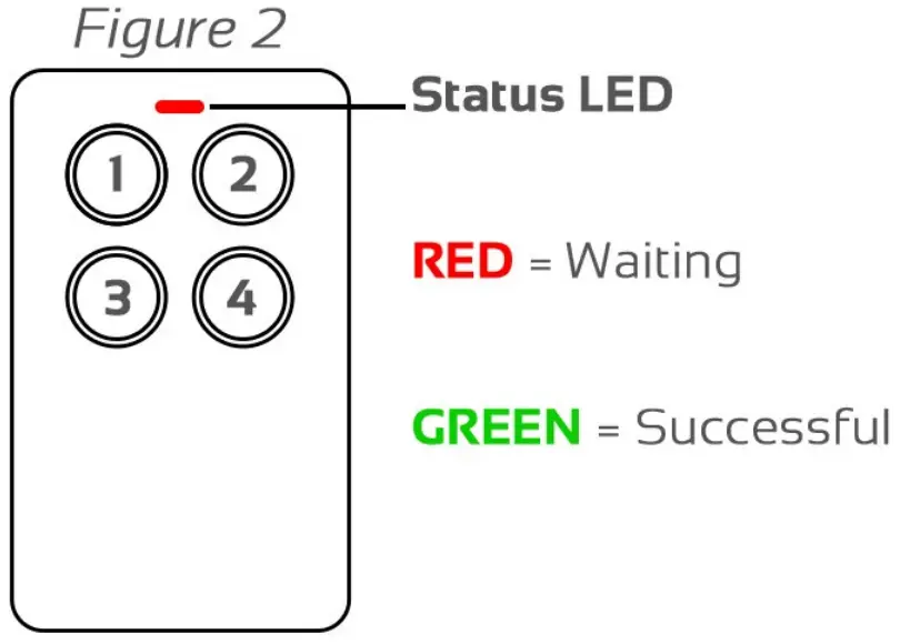
infinity link Default Procedure
Press and hold the gold ‘‘Default Button’ shown in ‘Figure 3″ while powering up the infinity link & continue to hold
The LED will display solid red and turn green when default is successful
Warning: Defaulting the infinity link will lose connection with all previously paired products.
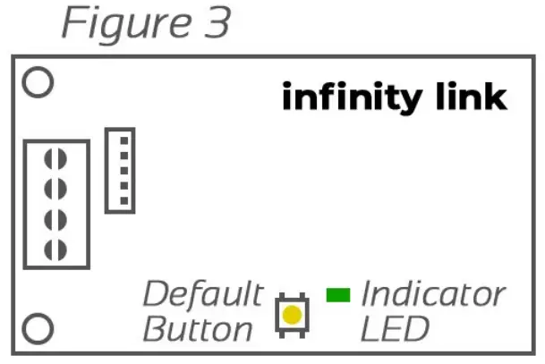 infinity link Indication LED
The indication LED shown in ‘Figure 3″ will illuminate green when receiving a wireless signal & also flash during system learn beeps.
Learning Remotes (consult control panel installation manual for advanced programming)
‘EC’ control panels have pre-configured user slots to simplify learning of wireless remotes.
These slots are located from users 140 to 189 as shown in ‘Pre-Configured User Slots’ table below:
- Enter installer programming mode on the alarm keypad
- Press PROG 18 ENTER followed by the user number you wish to learn (eg. 140), followed by ENTER Next press ENTER again to start the keypad beeps which indicates that the system is waiting for a remote button to be pressed
- Pressthe remote button you wish to learn and the keypad should stop beeping to indicate a successful learn
- Tolerant another button, press the right or left arrows on the keypad to go to next or previous user slot, then press ENTER, or press PROG then ENTER to exit installer programming
Pre-Configured User Slots
| Arm Users 140 – 149 |
Users 140 to 149 will ARM only Example: P18 E140 E E (learn beeps start) Press the remote button you wish to learn (learn beeps stop) This button will now ARM the system |
| Disarm Users 150 -159 |
Users 150 to 159 will DISARM only Example: P18 E150 E E (learn beeps start) Press the remote button you wish to learn (learn beeps stop) This button will now DISARM the system |
| Output 3 Users160 -169 |
Users 160 to 169 will operate OUTPUT 3 & DISARM at the same time Example: P18 E160 E E (learn beeps start) Press the remote button you wish to learn (learn beeps stop) This button will now DISARM the system & control output 3 at the same time |
| Output 4 Users170-179 |
Users 170 to 179 will operate OUTPUT 4 & DISARM at the same time Example: P18 E170 E E (learn beeps start) Press the remote button you wish to learn (learn beeps stop) This button will now DISARM the system & control output 4 at the same time |
| Panic Users 180 -189 |
Users 180 to 189 will operate as a PANIC button Example: P18 E180 E E (learn beeps start) Press the remote button you wish to learn (learn beeps stop) This button will now perform a PANIC function |
Remote 1 Example (oution colours are indicative only)
Remote 2 Example (out ton colours are indicative only)
Battery Low Reporting & Haptic Feedback
- P7E must be set to option 1 (infinity) to enable battery low reporting & for the remote to operate correctly.
- Haptic feedback is disabled when battery low is reported due to the remote entering power save mode.
- Battery low will be indicated to the control panel at 2.2V & below.
Cabinet & Transformer Specifications & Installation Requirements
- This product must be installed by a ‘Skilled person ‘who has training or experience in this equipment technology. A skilled person is expected to use their training or experience to identify energy sources that may cause pain or injury and take appropriate action to prevent unintentional harm to themselves & others
Specifications
| Manufacturer | Arrowhead Alarm Products Ltd. |
| Product Name | EC-CAB 1A. |
| Input Voltage 81 Frequency | 230 – 250VAC – 50Hz. |
| Rated Current | 150mA . |
| Transformer Output Voltage | 17VAC. |
| Transformer Output Current | MA. |
| Fuse | 250mA, S x 20mm Slow Blow. |
| Cabinet Material | ABS. |
| Environment | -20°C – 60°C,1096- 90% Relative Humidity. |
| Dimensions | W323 x H293 x D87mm. |
| Max Weight inc112V7SA Batt | 3.9Kg. |
| Mounting Height | 2m or lower |
| Mounting Fixings (not included) | Solid mount to wall with appropriate fixings. |
Mounting Location
This equipment is not suitable for use in locations where children are likely to be present.
Mount in a secure location, ideally out of sight of visitors &intruders.
This product is IPX0 & therefore is suitable for indoor applications only.
Make sure cabinet vents are clear of any immediate or potential obstructions, including linen &insulating material.
Do not mount in ceiling cavities or any area that is likely to exceed 50°C.
Strain Relief Mechanism & 230VAC Isolation
- This cabinet includes a strain relief mechanism which must be used for both fixed & portable applications
- First remove mechanism by breaking the tab shown here——”T
- Once removed, place the strain relief mechanism over the 230V cable & fix using the screws provided as shown
- Make sure the sheath or jacket of the 230V cable extends at least one-half the diameter of the cord or cable past the strain relief mechanism shown here
- Installation of a 230VAC disconnect device or isolator switch near the alarm cabinet is required for safety and servicing purposes.
Securing The Cabinet & Back Up Battery
- All SLA (sealed lead acid) batteries that are mounted in this cabinet must be secured using the 2 x cable tie locations provided
EliteControl & EliteCloud products are
proudly manufactured by
‘ Arrowhead
Alarm Products
www.aap.co.nz