Contents
ICE Company Limited RS28-OB Rider Auto Scrubber

Product Information
- Product Name: ICE RS28-OB Rider Auto Scrubber
- Manufacturer: ICE Company Limited
- Website: www.icecompanies.com, www.icerental.com
- Model Number: RS28-OB
- Serial Number: 8300008 REV.03 (06-2022)
- Specifications and parts are subject to change without notice.
- Contact Information:
- Address: XiangShi Road, LiaoBu, DongGuan, GuangDong, China
- Tel: 0769 – 81869000
- Fax: 0769 – 81863000
READ OPERATOR MANUAL CAREFULLY!
IMPORTANT: To ensure full warranty protection, please fill out & return your warranty card.
Please fill out at time of installation for future reference.
- Model No.: ………………………….
- Serial No.: ………………………….
- Machine Options: ………………………….
- Sales Rep.: ………………………….
- Sales Rep. Phone No.: ………………………….
- Customer ID Number: ………………………….
- Installation Date: ………………………….
HOW TO ORDER PARTS
Only use ICE Company supplied or equivalent parts. Parts and supplies may be ordered online,by phone, by fax or by mail.
- Identify the machine model.
- Identify the machine serial number from the data label.
- Ensure the proper serial number is used from the parts list.
- Identify the part number and quantity. Do not order by page or reference numbers.
- Provide your name, company name, customer ID number,billing and shipping address, phone number and purchase order number.
PROTECT THE ENVIRONMENT
- Please dispose of packaging materials,old machine components such as batteries, hazardous fluids, including antifreeze and oil, in an environmentally safe way according to local waste disposal regulations.
- Always remember to recycle.
SAFETY PRECAUTIONS
This machine is intended for commercial use. It is designed exclusively to scrub hard floors in an indoor environment and is not constructed for any other use. Only use recommended accessories. All operators shall read, understand and exercise the following safety precautions:
Do not operate machine:
- Unless trained and authorized.
- Unless you have read and understand the operators manual.
- Inflammable or explosive areas.
- With brake disabled.
- If not in proper operating condition.
Before starting machine:
- Make sure all safety devices are in place and operate properly.
- Check brakes and steering for proper operation.
When using machine:
- Go slow on inclines and slippery surfaces.
- Follow all safety guidelines.
- Be very careful when using the machine in reverse.
- Reduce speed when turning.
- Report and fix any damage to machine prior to operating it.
- Never allow children to play on or around.
Before leaving or servicing machine:
- Stop on level surface.
- Turn off machine.
When servicing machine:
- Read operators manual thoroughly prior to operating or servicing this machine.
- Use manufacturer supplied or approved replacement parts.
- Secure machine with wheel blocks prior to jacking the machine up.
- Use approved jack or hoist to safely elevate the machine.
- Disconnect batteries prior to working on machine.
- Wear gloves when handling batteries or battery cables.
- Avoid any contact with battery acid
- Avoid moving parts. Do not wear loose fitting clothing while servicing machine.
WARNING
- Batteries emit hydrogen gas. Explosion or fire can result from hydrogen gas. Keep sparks and open flames away! Keep battery compartment open when charging.
- Flammable materials can cause an explosion or fire. Do not use flammable materials in tanks.
- Flammable materials or reactive metals can cause explosion or fire.
- Do not pick up.
MACHINE COMPONENTS

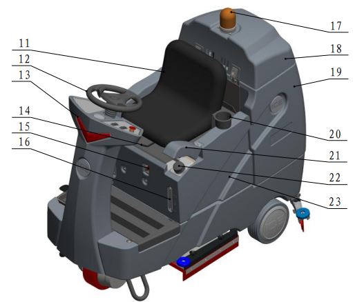
- Solution tank
- Hose fill port & Cap
- Squeegee assembly
- Wheels, 10 inch
- Orbital head assembly
- Side squeegee assembly
- Watching window, onboard battery charger
- Brake pedal
- Propel pedal
- Front drive wheel
- Operator seat
- Steering wheel
- LED light, work
- Adjusting handle, seat
- Off-board battery charger receptacle
- Detergent level watching window
- Warning light
- Recovery tank cover
- Recovery tank
- Cup holder
- Cap
- Detergent bottle
- Battery box
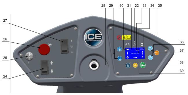
- Directional switch
- Main power key switch
- Emergency stop switch
- Warning light switch
- Vacuum motor switch & indicator
- Detergent dosage adjusting buttons & indicator
- Batteries meter
- LED display screen
- Fault indicator
- Fault code
- Fault message
- Hour meter
- Solution flow adjusting buttons & indicator
- Horn button
- 1-Step switch & Indicator
- Brush pressure adjusting button & indicator
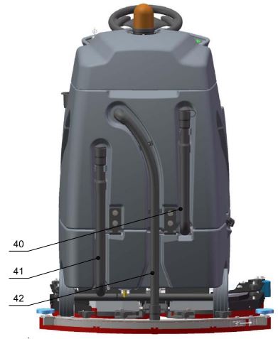
- Drain hose, recovery tank
- Drain hose, solution tank
- Vacuum hose
MACHINE SET UP & INSTALLATION
UNCRATING MACHINE
Be sure and check packing carton for any damage. Immediately report any damage to carrier. Check the contents of package to ensure that the following items are included:
- Machine
- 4-6V Batteries
- Squeegee assembly
- 2-Pad drivers
- 2-Brushes
- Uncrate the wooden box, place the top board on the edge of pallet, lie in the front of the machine, as below shown.

- WARNING: Do not operate machine unless you have read & understood this manual.
- Install batteries.(see INSTALLING BATTERIES)
- Turn on the Main power key switch (machine components, #25), make sure the Squeegee assembly (machine components, #3) and the Scrub head assembly (machine components, #5) is off the floor.
- Sit in the Operator seat (machine components, #11), hold the Steering wheel (machine components, #12), press the Propel pedal (machine components, #9) and driving slowly the machine down from the slope.
INSTALLING BATTERIES
WARNING: Batteries emit hydrogen gas.
- Explosion or fire can result from hydrogen gas.Keep sparks and open flames away! Keep battery compartment open when charging.
Recommended battery spec
- 4-6V, 260AH@20HR deep cycle batteries.
Max. batteries dimensions
300mm (L) X 180mm (W) X 290mm (H)
- Turn the Main power key switch off.
- Remove the Operator seat & the Battery box (machine components, #23).
- Carefully place the batteries into the compartment as shown in figure below. Place the battery brace at the rear of the batteries.
- NOTE: Do not drop the batteries into the compartment!
- Connect battery cables to posts in numbered order as shown in drawing below.

- NOTE: RED to POSITIVE and BLACK to NEGATIVE.
- Reinstall the Operator seat and the Battery box.
MACHINE SET UP
INSTALLING BRUSHES OR PADS
- Turn off the 1-Step switch (machine components, #38) and raise the Orbital head assembly off the floor, then stop machine on the level surface, remove the key and ensure the machine is turned off.
- Attach the appropriate pad to the pad driver surface.
MOUNTING THE SQUEEGEE ASSEMBLY
- Turn off the 1-Step switch and raise the Squeegee assembly off the floor.
- Mount the squeegee assembly to the squeegee pivot bracket. make sure the knobs are completely seated into the slots before securing knobs.
- Connect the Vacuum hose (machine components, #42) to the squeegee assembly. Loop the hose by using the hose clip provided.
- Check the squeegee blades for proper adjustment.
FILLING THE SOLUTION TANK
- The machine is equipped with a Hose fill-port (machine components, #2) at the side of the machine, and a bucket fill-port located under the recovery tank.
NOTE
- Before accessing the bucket fill-port make sure that the recovery tank is empty.
- When filling the solution tank with a bucket, make sure that the bucket is clean. Do not use the same bucket for filling and draining the machine.
WARNING: Do not put any flammable materials into solution tank. this can cause an explosion or a fire.
FILLING THE DETERGENT BOTTLE
- The machine is equipped with a 6 liters Detergent bottle (machine components, #22). Open the Cap (machine components, #21) you can fill detergent, and watch the liquid level on the Detergent level watching window (machine components, #16).
- The ratio of water and detergent is 0~5%, you can adjust this ratio via pressing the Detergent dosage adjusting buttons (machine components, #29).
NOTE: Only use recommended cleaning chemicals. Contact your janitorial supply distributor for recommendations on proper chemicals.
MACHINE OPERATION
WARNING: Do not operate machine unless you have read and understand this manual.
PRE-OPERATION CHECKS
- Check the tank cover seals for damage.
- Drain the recovery tank, check the vacuum fan inlet filter, clean them if necessary.
- Check the vacuum hose for debris or blockage.
- Check the squeegees for damage, wear and for deflection adjustment.
- Check whether Pad/Bruch is installed properly .
- Check the brakes and steering for proper operation.
OPERATION THE MACHINE
- Sit in the Operator seat, adjusting the seat to comfortable place by pushing the Seat adjustment handle (machine components, #14).
- NOTE: The machine will not travel unless the operator is sitting in the operator seat.
- Turn on the machine. Check the LED display screen (machine components, #31) , if there are fault codes (machine components, #33) and the Fault indicator (machine components, #32) is blink, please Do Not operation the machine unless the faults have been eliminated (please see FAULT CODES AND ELIMINATE section).
- Select the preferred settings by pressing the Brush pressure adjusting buttons (machine components, #39) , Solution flow adjusting buttons (machine components, #36) and Detergent dosage adjusting buttons.
- NOTE: Use the minimal pressure and flow as possible.
- Turn on the 1-Step switch, the Scrub head assembly and the Squeegee assembly will lower down automatically, all the presetting functions will turn on.
- The machine can scrub in both forward and backward, place the Directional switch (machine components, #24) in the forward direction is to move forward, backward is to move backward. The horn will sound and the squeegee will raise automatically (the vacuum motor will turn off after a short delay) when drive machine backwards. This is to prevents damaging the squeegee.
- NOTE: Go slow when drive machine backwards.
- Press the Propel pedal, the machine start scrubbing, the speed can be adjusted by controlling the force of foot stepping, light is slow, heavy is fast.
- NOTE: Go slow on inclines and slippery surfaces.
- To stop scrubbing, turn off the 1-Step switch, the scrub head will raise automatically, the squeegee will also raise after a short delay (the vacuum indicator flashing), please keep moving until the dirty water is picked up, and then release the propel pedal and stop scrubbing.
- Turn off the machine.
BRAKE DEVICE
- The machine is drived by the Front drive wheel (machine components, #10), that is equipped with a brake device. When you release the Propel pedal, the machine will stop travel, the park brake will engage after a short delay.
- The machine is equipped with a Brake pedal (machine components, #8), that can be used to control the machine if quicker stopping is needed or if operating on an incline.
EMERGENCY STOP BUTTON
- The machine is equipped with an Emergency stop button (machine components, #26), please push it if an emergency, that will shut off all power of machine and brake immediately.
- To restart the machine, please reset the Emergency stop button, and turn off the Main power key switch, then turn on key switch.
NOTE: Please hold the steering wheel when emergency stop.
WHILE OPERATING MACHINE
WARNING: Fire Or Explosion Hazard. Do Not Pick Up Flammable Materials Or Reactive Metals.
- Go slow on inclines and slippery surfaces, go slow when turn and reverse. Do not operate the machine on inclines that exceed 7% (4°).
- Drive machine in a straight path as possible, avoid turning the Steering wheel too sharply when machine is in motion. avoid sudden turns except emergencies.
- Do not keep the machine in the same position with pad / brush spinning, keep the machine moving to prevent damage to floor finish.
- If the squeegee assembly leaves streaks on the floor, raise the squeegee off the floor and wipe the blades down with a damp cloth. Pre-sweep the area to prevent leaving streaks on the floor.
- To obtain the optimum cleaning performance, you can adjust the brush pressure, solution flow and detergent dosage as your required. If poor picking up water performance is observed, please stop scrubbing and check the squeegee blade, adjust or replace if necessary.
- If the dirty water path exceed the width of squeegee, please adjust the side squeegee assembly.
- Pour a recommended defoamer into the recovery tank if excessive foam appears.
- WARNING: The foam do not activate water level switch, excessive foam may result in vacuum motor damage.
- Press the Horn button (machine components, #37) to alert if necessary.
- The machine is equipped with a Warning light (machine components, #17), you can select turn ON or OFF by the Warning light switch (machine components, #27).
- If there is a fault code F10 (Batt low) on the LED display screen, the machine will stop scrubbing and alarm, please drive the machine to charging.
- If there is a fault code F08 (Rec Tank Full) on the LED display screen, the vacuum motor will stop working and alarm, please drive the machine to drain water. If there is a fault code F09 (Soln Tank Empty) on the LED display screen, the Detergent system will stop working and alarm, please fill the solution tank.
- If there are other fault codes on the LED display screen, please turn off the machine, eliminate the fault (please see FAULT CODES AND ELIMINATE section), then restart machine.
- For heavily soiled areas, please use DOUBLE SCRUBBING mode. The first time: Turn on the 1-Step switch, then press the Vacuum motor switch (machine components, #28), its indicator will turn off and the squeegee will raise automatically, then start to scrubbing this areas without picking up water. The second time: turn on the Vacuum motor switch, the squeegee will lower down automatically, and then start to scrubbing and picking up water.
- If you only want to pick up water needn’t scrubbing, Turn on the Vacuum motor switch (squeegee will lower down) and turn off the 1-Step switch (if it is ON), the scrub head will raise and then start to working.
TANK DRAINING
DRAINING THE RECOVERY TANK
Any time scrubbing is completed, or when refilling solution tank, the recovery tank should be drained and cleaned.
WARNING: If the recovery tank is not drained when the solution tank has been refilled, foam or water may enter the float shutoff screen and cause damage to the vacuum motor.
- While holding the Recovery tank drain hose (machine components, #40) upward, remove the cap and lower hose to drain.
- Open the Recovery tank cover (machine components, #18) and rinse out the tank. Use a rag to remove any excess dirt. Clean the vacuum fan inlet filter located in the recovery tank .
DRAINING THE SOLUTION TANK
Any time scrubbing operation is completed, the solution tank should be drained and cleaned.
- While holding the Solution tank drain hose (machine components, #41) upward, remove the cap and lower hose to drain.
- Rinse the solution tank with clean water after every use. This will help prevent chemical buildup and clogging of the solution lines.
BATTERY CHARGING
WARNING: Fire Or Explosion Hazard.
Batteries Emit Hydrogen Gas. Keep Sparks and Open Flame Away. Keep Battery Compartment Propped Open When Charging.
Use only apprved chargers with the following specifications:
- Automatic shut off circuit
- Deep cycle charging
- Output current of 20-30 Amps
- Output voltage of 24 volts
ON-BOARD BATTERY CHARGER
As standard configuration, the machine is equipped with the On-board battery charger. The settings of On-board battery charger had been set for the recommended batteries type.
WARNING: The On-board battery charger setting’s change are to be completed by authorized service centers only. Failure to properly set will result in the batteries or charger damage.
- Transport the machine to a well ventilated area.
- Turn the machine off.
- If charging wet (lead acid) batteries check the fluid level before charging.
- Prop up the Operator seat by the support stand for ventilation.
- Connect the charger’s AC power supply cord to a properly grounded receptable.
- The charger will automatically begin to charge, you can watching the charging status on the window (machine components, #7), once the charging cycle begins, the indicator lights will progress from red, yellow to green. when the green indicator light comes on, the charging cycle is done. Unplug the charger cord.
NOTE: The machine will can not operate when charging.
PREVENTATIVE MAINTENANCE
WARNING
- Before performing any maintenance on the machine, be sure that the power is turned off, or the batteries are disconnected!
- Repairs are to be completed by Authorized service centers only. Any repairs completed by unauthorized persons will avoid the warrenty.
DAILY MAINTENANCE
- Remove pad driver/ brush and clean with approved cleaner.
- Drain recovery and solution tanks completely and rinse out with clean water. Visually check the recovery tank for debris and clean out as necessary.
- Raise the squeegee assembly off floor and wipe it down with a damp towel. Be sure to store the squeegee in the up position.
- Remove the vacuum fan inlet filter and rinse it out with clean water.
- Clean machine with an approved cleaner and a damp towel.
- Recharge the batteries.
- Check the condition of the squeegee blade wiping edge, rotate blade if worn.
MONTHLY MAINTENANCE
- Clean the battery tops to prevent corrosion.
- Check for loose battery cable connections.
- Inspect and clean the recovery tank cover seal. Replace it if damaged.
- Lubricate all grease points and pivot points with silicon spray and approved grease.
- Check the machine for loose nuts and bolts.
- Check the machine for leaks.
MOTOR MAINTENANCE
- Contact your local Distributor for any motor maintenance.
- Motor should have the brushes checked every 250 hours. Brushes should be replaced when they are worn to a length of 10 mm or less.
BATTERY MAINTENANCE
WARNING
- Batteries emit hydrogen gas and an explosion o fire can result. Keep sparks and fire away from batteries at all times.
- Whenever servicing batteries, be sure to wear protective gloves. Avoid contact with battery acid at all times.
NOTE: For the best machine performance, keep batteries charged at all times. Do not let them sit in a discharged condition.
- Always follow the battery charging directions as outlined in the BATTERY CHARGING section of this manual.
- Keep battery tops and terminals free from corrosion. A strong solution of baking soda and water is the best way to keep the batteries corrosion free. DO NOT ALLOW THE BAKING SODA / WATER SOLUTION TO ENTER THE BATTERY CELLS.
- Use a wire brush with the baking soda solution to properly clean the battery posts and connections.
- Check battery connections for wear and loose terminals. replace if necessary.
MACHINE STORAGE
- Always store the machine indoors.
- Always store the machine in a dry area.
- Always store the machine in its upright position.
- Always store the machine with the pad driver/ brush raised off the floor.
- Always store the machine with the squeegee assembly raised off the floor.
- If storing in an area which may reach freezing temperatures, be sure to drain all fluids from the machine prior to storage. Any damage caused by freezing temperatures will not be covered by the warranty.
- Drain the recovery tank.
- Drain the solution tank of all fluid.
FAULT CODE & SOLUTION
The machine is equipped with a LED display screen (see Machine components, item # 31), the LED screen will display the operating hours (see Machine components, item # 35) and the battery level status (see Machine components, item # 30). When the machine detects a fault, there will be a Fault code (see Machine components, item #33) & Fault message (see Machine components, item #34) display on the LED screen, and the Fault indicator (see Machine components, item #32) will flash continuously, accompany an audible alarm Occasionally.
Once fault occuring, please DO NOT continue operate the machine unless the fault are eliminated. Turn off the machine, then to solve the fault, the fault code & message will be eliminated when machine restart. If the fault is occurred frequently, or the fault can’t be eliminated, please contact ICE service center. Please refer to the below table to determine the fault cause and the solution.
| FAULT CODE | FAULT MESSAGE | FAULT CAUSE | SOLUTION |
| F01 | Seat Empty | Not sit in the seat | Sit in the operator seat |
| F02 | Squeegee Actt O.L. RE-START! | Squeegee lifting actuator is overload |
Turn off the machine,after a moment, RE-START machine. |
| F03 | Bru Actt O.L. RESTART! | Scrub head lifting actuator is overload | |
| F04 | Vac Mtr O.L. RE-START! | Vacuum motor overload | |
| F05 | Left Bru Mtr O.L. RE-START! | Left brush motor is overload | |
| F06 | Right Bru Mtr O.L. RE-START! | Right brush motor is overload | |
| F07 | Propel Mtr O.L. RE-START! | Propel motor overload | |
| F08 | RecTank Full | Recovery tank is full | Drain the Recovery tank |
| F09 | Soln Tank empty | Solution tank is empty | Fill the solution tank |
| F10 | Batt Low Charge Batt | Battery is low | Charge the battery |
| F11 | Batt Empty Charge Batt NOW | Battery is empty | Charge the battery NOW |
| F12 | Brake Wiring Error | Bad Brake wiring | Check the brake wiring |
| F13 | Release Foot pedal | Stepping the propel pedal when starting machine | Release the propel pedal |
| F14 | Replace Brake Assy | Bad Brake assembly | Replace the brake assembly |
| F16 | Control Unit Overheat!
Wait |
Control Unit Overheat | Turn off the machine,after a moment,
RE-START machine |
| F17 | Replace Control Unit | Control Unit Fault | Replace the control unit |
| F18 | Replace Accel Pedal Sensor | Bad Accelerator pedal sensor | Replace accelerator pedal sensor |
| F19 | Replace Brake pedal sensor | Bad Accelerator pedal sensor | Replace accelerator pedal sensor |
| F20 | Check Left Brush motor | Bad left brush motor | Check left brush motor/ wiring |
| F21 | Check Vac Mtr | Bad Vacuum motor or wiring | Check the vacuum motor / Wiring |
| F22 | Check Soln Solenoid | Solution solenoid wiring fault | Check the wiring & Contactors |
| F23 | Replace Soln solenoid | Bad Solution solenoid | Replace the solution solenoid |
| F24 | Check Propel Motor | Bad propel motor | Check the propel motor / Wiring |
| F25 | Check Right Brush motor | Bad right brush motor | Check right brush motor/ wiring |
| F40 | Check Proximity Sw | Proximity switch fault | Check the Proximity switch |
| F42 | Replace Control Unit | Bad Control Unit | Replace the control unit |
| F43 | Turn Dead Sw Off
RE-START! |
Emergency stop button activated | Release emergency stop button and restart machine |
| F44 | Replace Control Unit |
Bad Control Unit |
Contact service center, Replace the Control Unit |
| F45 | Return Control Unit | ||
| F46 | Return Control Unit | ||
| F47 | Return Control Unit | ||
| F48 | Return Control Unit |
TECHNICAL SPECIFICATIONS
| MODEL | RS28-OB |
| LENGTH | 61.6 in / 1,565 mm |
| WIDTH (MACHINE WITH SCRUB HEAD) | 31.5 in / 800 mm |
| HEIGHT | 56.7 in / 1,440 mm |
| WEIGHT | 640 lbs / 290 Kg |
| WEIGHT WITH BATTERIES | 900 lbs / 410 Kg |
| RECOVERY TANK CAPACITY | 29 Gal / 110 L |
| SOLUTION TANK CAPACITY | 29 Gal / 110 L |
| SQUEEGEE WIDTH | 40 in / 1,030 mm |
| CLEANING PATH WIDTH | 28 in / 710 mm (28in x 14in Pad) |
| PRODUCTIVITY RATE PER HOUR (IN THEORY) | 49, 500 ft2
4,600 m2 |
| TRAVEL SPEED (TRANSPORT) | 4 Mile / h
6.5 Km / h |
| MINIMUM AISLE TURN | 75 in / 1,900 mm |
|
PAD/BRUSH PRESSURE |
80 lbs / 35 Kg
120 lbs / 55 Kg 160 lbs / 75 Kg |
| SOLUTION FLOW | 0 ~ 0.7 Gal / Min
0 ~ 2.7 L / Min |
| BATTERIES | 4 x 6V, 240AH@20Hr |
| VOLTAGE | 24V DC |
| DRIVE WHEEL | 1.1 hp / 0.8 KW |
| BRUSH MOTOR | 0.75 hp / 0.55KW,2200 RPM |
| VIBRATIONS @ SEAT | < 2.5 m / s2 , < 8.2 ft / s2 |
| VACUUM MOTOR | 0.6 hp / 0.45KW |
| VACUUM WATER LIFT (MAX) | 70 in. H2O / 1780 mm. H2O |
| RUN TIME PER CHARGE | 3.5~4.0 Hours |
| DECIBEL RATING AT OPERATOR’S EAR, INDOORS |
68 dB(A) |
| GRADE LEVEL, MAX | Scrubbing: 4°/7% Transporting (empty):10°/17.5% |
PARTS LIST
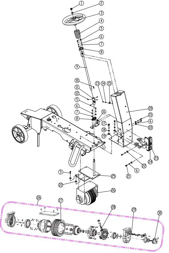
MAIN FRAME GROUP

MAIN FRAME GROUP
| DIA NO. | PART NUMBER | DESCRIPTION | SERIAL NUMBER | NO REQ’D |
| 1 | 8340160 | MAIN FRAME, WELDED | 1 | |
| 2 | 8310133 | RUBBER GROMMET | 5 | |
| 3 | 8310930A | PERISTALTIC PUMP, KIT | 1 | |
| 8310931 | TUBING, PUMP | 1 | ||
| 4 | 1421409 | FLAT WASHER, M4×∮9×0.8 | 2 | |
| 5 | 1422411 | LOCK WASHER M4 | 2 | |
| 6 | 1221412 | SCREW, PAN HEAD, M4×12 | 2 | |
| 7 | 8310119 | 10″ WHEEL, PU TIRE | 2 | |
| 1612605 | BALL BEARING,6205-2RS | 4 | ||
| 8 | 1436025 | RETAINING RING, 25MM | 2 | |
| 9 | 8310150 | WHEEL CAP | 2 | |
| 10 | 6210131 | NYLON, CLAMP | 5 | |
| 11 | 1421510 | FLAT WASHER, M5×∮10×1.0 | 5 | |
| 12 | 1221512 | SCREW, PAN HEAD, M5×12 | 5 | |
| 13 | 8310120 | BRACKET, STAND | 2 | |
| 14 | 1421824 | FLAT WASHER, M8×∮24×2.0 | 3 | |
| 15 | 1422821 | LOCK WASHER M8 | 3 | |
| 16 | 1021825 | BOLT, HEX, M8×25 | 3 | |
| 17 | 8210118 | STATIC STRAP | 1 | |
| 18 | 8310708A | HORN, 24VDC, KIT | 1 | |
| 19 | 1421307 | PLAT WASHER, M3×∮7×0.5 | 4 | |
| 20 | 1211316 | SCREW, PAN HEAD, M3×16 | 2 |
STEERING & DRIVE WHEEL GROUP
| DIA
NO. |
PART
NUMBER |
DESCRIPTION | SERIAL NUMBER | NO
REQ’D |
| 1 | 1113014 | LOCK NUT, M14 | 1 | |
| 2 | 1421428 | FLAT WASHER, M14×∮28×2.0 | 1 | |
| 3 | 8310602 | STEERING WHEEL | 1 | |
| 8310699A | CUSHION WITH ICE LOGO | 1 | ||
| 4 | 8310608 | BELLOWS, SHAFT, STEERING | 1 | |
| 5 | 1021825 | BOLT, HEX HEAD, M8×25 | 8 | |
| 6 | 1422821 | LOCK WASHER, M8 | 6 | |
| 7 | 1421816 | FLAT WASHER, M18×∮16×1.6 | 4 | |
| 8 | 8310609 | BEARING, FLANGE | 2 | |
| 9 | 8310605 | SHAFT, STEERING WHEEL | 1 | |
| 10 | 1654025 | KEY, 4.75×4.75×25.4 | 2 | |
| 11 | 8313614 | U-JOINT | 1 | |
| 12 | 1534508 | SET SCREW, M5 ×8 | 4 | |
| 13 | 1123507 | LOCK NUT, M5 | 3 | |
| 14 | 1421510 | FLAT WASHER, M5×∮10×1.0 | 3 | |
| 15 | 6210131 | CLAMP, NYLON | 3 | |
| 16 | 8310645 | BRACKET, FLANGE BEARING | 1 | |
| 17 | 1021060 | BOLT, HEX HEAD, M10×60 | 4 | |
| 18 | 1422026 | LOCK WASHER, M10 | 4 | |
| 19 | 1421030 | FLAT WASHER, M10×∮30×2.5 | 4 | |
| 20 | 8310601 | SUPPORT BRACKET, STEERING | 1 | |
| 21 | 1021820 | BOLT, HEX HEAD, M8×20 | 4 | |
| 22 | 1421824 | FLAT WASHER, M14×∮24×2.0 | 8 | |
| 23 | 8310640 | ACCELERATOR/ BRAKE PEDAL | 1 | |
| 24 | 8310431 | HALL SENSOR WITH CABLE | 1 | |
| 25 | 8310603 | STEER-CONTROL ASSY. | 1 | |
| 26 | 8310650 | DRIVE WHEEL, 24VDC 800W | 1 | |
| 27 | 8310611 | PU TIRE, DRIVER WHEEL | 1 | |
| 28 | 8310612 | ARMATURE BRUSH | 4 | |
| 29 | 8310613 | BRUSHES CONNECTION BOX | 2 | |
| 30 | 8310618A | ELECTRICALLY RELEASED BRAKE | 1 |
SOLUTION TANK GROUP
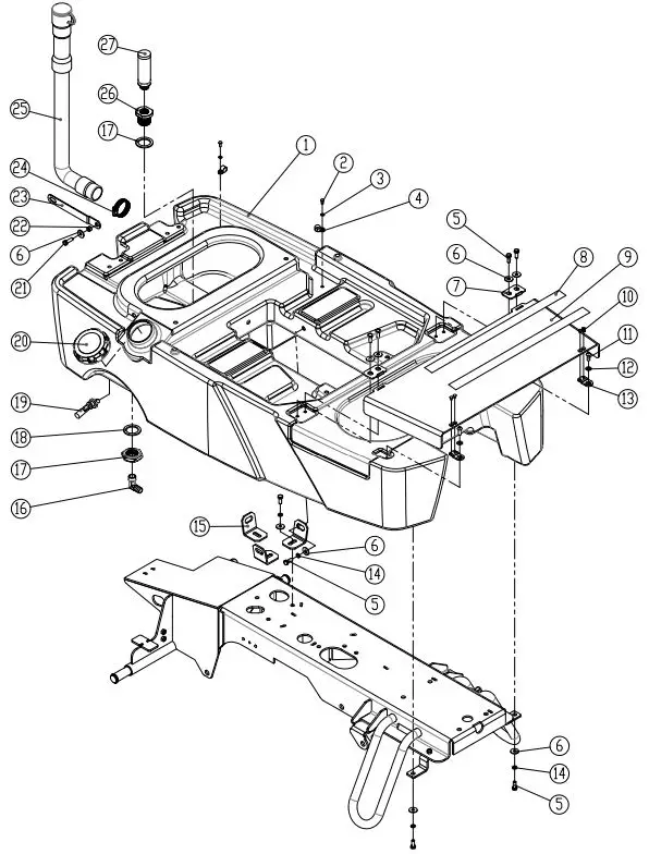
| NO. | PART NUMBER | DESCRIPTION | SERIAL NUMBER | NO REQ’D |
| 1 | 8310101 | SOLUTION TANK | 1 | |
| 2 | 1221512 | SCREW, PAN HEAD, M5×12 | 2 | |
| 3 | 1421510 | FLAT WASHER, M5×∮10×1.0 | 2 | |
| 4 | 8113009 | CLAMP, NYLON | 2 | |
| 5 | 1021820 | BOLT, HEX HEAD, M8×20 | 12 | |
| 6 | 1421824 | FLAT WASHER, M8×∮24×2.0 | 13 | |
| 7 | 8310139 | PLATE | 2 | |
| 8 | 8310151A | NON-SLIP MAT | 2 | |
| 9 | 8310132 | FOOTREST PLATE | 1 | |
| 10 | 1222508 | SCREW, M5×8 | 4 | |
| 11 | 1512820 | SCREW, HEX SOCKET, M8×20 | 2 | |
| 12 | 1421816 | FLAT WASHER, M8×∮16×1.6 | 2 | |
| 13 | 8310140 | JUNCTION PLATE | 2 | |
| 14 | 1422821 | LOCK WASHER, M8 | 8 | |
| 15 | 8310130 | BRACKET, SOLUTION TANK MNTG | 3 | |
| 16 | 8310124 | ELBOW, G1/2 | 1 | |
| 17 | 8310142 | NUT, M36 | 1 | |
| 18 | 8310141 | SEALING | 2 | |
| 19 | 8310238A | SENSOR, SOLUTION LEVEL, KIT | 1 | |
| 20 | 8310125 | CAP, SOLUTION TANK | 1 | |
| 21 | 1021825 | BOLT, HEX HEAD, M8×25 | 1 | |
| 22 | 8310225 | SLEEVE, ∮8.1×∮12.7×7.8 | 1 | |
| 23 | 8310224 | ARM, RECOVERY TANK SUPPORT | 1 | |
| 24 | 1962050 | CLAMP, 2 INCH | 1 | |
| 25 | 8011040 | HOSE ASSEMBLY | 1 | |
| 26 | 8310123 | ADAPTER, STRAINER ASSY | 1 | |
| 27 | 8310122 | STRAINER ASSY | 1 |
RECOVERY TANK GROUP

| DIA
NO. |
PART
NUMBER |
DESCRIPTION | SERIAL NUMBER | NO
REQ’D |
| 1 | 8310238A | SENSOR, SOLUTION LEVEL, KIT | 1 | |
| 2 | 8310201 | RECOVERY TANK | 1 | |
| 3 | 8310237 | FILTER, DUST | 1 | |
| 4 | 1021820 | BOLT, HEX HEAD, M8×20 | 21 | |
| 5 | 1421824 | FLAT WASHER, M8×∮24×2.0 | 25 | |
| 6 | 8310227 | HINGE, WELDED | 2 | |
| 7 | 1513820 | SCREW, HEX SOCKET, M8×20 | 2 | |
| 8 | 8310226 | HINGE, LEAF | 2 | |
| 9 | 8310250 | DEBRIS COLLECTOR | 1 | |
| 10 | 8012008 | BUSHING | 2 | |
| 11 | 1421618 | FLAT WASHER, M6×∮18×1.6 | 2 | |
| 12 | 1321413 | SELF-TAPPING, ST4.8 x 13 | 2 | |
| 13 | 1221516 | SCREW, PAN HEAD, M5×16 | 8 | |
| 14 | 1421510 | FLAT WASHER, M5×∮10×1.0 | 12 | |
| 15 | 2310129 | CLAMP, HOSE | 2 | |
| 16 | 6210122 | CLAMP, HOSE | 2 | |
| 17 | 8011040 | DRAIN HOSE | 1 | |
| 18 | 1962050 | CLAMP, 2 INCH | 1 | |
| 19 | 4010316 | ICE LOGO | 2 | |
| 20 | 8310126 | HINGE ASSY. | 2 | |
| 21 | 8113009 | CLAMP, NYLON | 4 | |
| 22 | 1221512 | SCREW, PAN HEAD, M5×12 | 4 | |
| 23 | 8310221 | SPACER | 2 | |
| 24 | 8310220 | COMPRESSION SPRING | 2 | |
| 25 | 8310222 | FLAT WASHER, LARGE | 4 | |
| 26 | 8310216 | COVER, SOLUTION TANK | 1 | |
| 27 | 8310219 | SEALING STRIP | 1 | |
| 28 | 1022860 | BOLT, HEX HEAD, M8×60 | 2 | |
| 29 | 1123810 | LOCK NUT, M8 | 1 | |
| 30 | 1021825 | BOLT, HEX HEAD, M8×25 | 1 | |
| 31 | 8310225 | SLEEVE, ∮8.1×∮12.7×7.8 | 2 | |
| 32 | 8310223 | ARM, RECOVERY TANK SUPPORT | 1 | |
| 33 | 8310215 | BRACKET, RECOVERY TANK SUPPORT | 1 | |
| 34 | 8310211 | BRACKET, SUPPORT | 1 | |
| 35 | 8310214 | SPACER, RUBBER | 1 |
RECOVERY TANK COVER GROUP

| DIA
NO. |
PART NUMBER | DESCRIPTION | SERIAL NUMBER | NO
REQ’D |
| 1 | 1221512 | SCREW, PAN HEAD, M5×12 | 5 | |
| 2 | 1421510 | FLAT WASHER, M5×∮10×1.0 | 9 | |
| 3 | 8310138A | CAUTION LIGHT, KIT | 1 | |
| 4 | 1123507 | LOCK NUT, M5 | 2 | |
| 5 | 8310241 | PLATE, CATUION LIGHT | 1 | |
| 6 | 8310202 | RECOVERY TANK COVER | 1 | |
|
7 |
8310299 | VACUUM MOTOR, 3 STAGE, KIT | 1 | |
| 8112008 | CA RB O N BRUS H F O R VA CUUM MOTOR | 2 | ||
| 8 | 8310207 | VACUUM HOSE | 1 | |
| 9 | 1962050 | CLAMP, 2 INCH | 2 | |
| 10 | 1123608 | LOCK NUT, M6 | 8 | |
| 11 | 1421612 | FLAT WASHER, M6×∮12×1.6 | 4 | |
| 12 | 8310204 | ADAPTER, VACUUM HOSE | 1 | |
| 13 | 8310205 | GASKET, ADAPTER | 1 | |
| 14 | 8310230 | GASKET, DUST FILTER | 1 | |
| 15 | 1021620 | BOLT, HEX HEAD, M6×20 | 4 | |
| 16 | 8310232 | BRACKET | 1 | |
| 17 | 1421618 | FLAT WASHER, M6×∮18×1.6 | 12 | |
| 18 | 1022600 | BOLT, HEX HEAD, M6×100 | 1 | |
| 19 | 8310228 | SUPPORT, RECOVERY TANK COVER | 1 | |
| 20 | 8310231 | SLEEVE, ∮6.4×∮9.5×4 | 1 | |
| 21 | 1021616 | BOLT, HEX HEAD, M6×16 | 1 | |
| 22 | 8310236 | SPACER, NYLON | 1 | |
| 23 | 8310235 | SLEEVE, ∮6.4×∮9.5×8 | 1 | |
| 24 | 8310229 | SEALING STRIP | 1 | |
| 25 | 1021610 | BOLT, HEX HEAD, M6×10 | 2 | |
| 26 | 1422616 | LOCK WASHER, M6 | 3 | |
| 27 | 1021820 | BOLT, HEX HEAD, M8×20 | 4 | |
| 28 | 1421824 | FLAT WASHER, M8×∮24×2.0 | 4 | |
| 29 | 8310203 | PLATE, VACCUM MOTOR MNTG | 1 | |
| 30 | 8310208 | ISOLATER, M6 | 3 | |
| 31 | 8310209 | BRACKET, VACCUM MOTOR | 1 | |
| 32 | 8310234 | INSULATION | 1 | |
| 33 | 1311316 | SCREW, SELF-TAPPING, ST4.8×16 | 4 | |
| 34 | 8310206 | SEAL, FAN | 1 |
CONTROL PANEL GROUP

| DIA
NO. |
PART NUMBER | DESCRIPTION | SERIAL NUMBER | NO REQ’D |
| 1 | 1221512 | SCREW, PAN HEAD, M5×12 | 8 | |
| 2 | 1421510 | FLAT WASHER, M5×∮10×1.0 | 11 | |
| 3 | 8311703 | DECAL, CONTROL PANEL | 1 | |
| 4 | 8311702 | PLATE, CONTROL PANEL | 1 | |
| 5 | 8310712 | GASKET, CONTROL PANEL | 1 | |
|
6 |
8310773 | PCB, CONTROL PANEL (AGM / EN) | 1 | |
| 8310775 | PCB,CONTROL PANEL (WET FLOODED / EN) | 1 | ||
| 7 | 1221306 | SCREW, PAN HEAD, M3×6 | 5 | |
| 8 | 8310701 | CONROL HOUSING | 1 | |
| 9 | 1421824 | FLAT WASHER, M8×∮24×2.0 | 4 | |
| 10 | 1422821 | LOCK WASHER, M8 | 4 | |
| 11 | 1021825 | BOLT, HEX HEAD, M8×25 | 4 | |
| 12 | 1321110 | SCREW, SELF-TAPPING, ST3.5×10 | 3 | |
| 13 | 1421409 | FLAT WASHER, M4×∮9×0.8 | 3 | |
| 14 | 8133610 | LED LIGHT, KIT | 1 | |
| 15 | 8133601 | BASE, LED LIGHT | 1 | |
| 16 | 1221520 | SCREW, PAN HEAD, M5×20 | 3 | |
| 17 | 8133602 | COVER, LED LIGHT | 1 | |
| 18 | 4010316 | ICE LOGO | 1 | |
| 19 | 8310711 | GASKET, SWITCH PANEL | 1 | |
| 20 | 8310702 | PLATE, SWITCH PANEL | 1 | |
|
21 |
8310704 | DECAL, SWITCH PANEL, RS32 | 1 | |
| 8312704 | DECAL, SWITCH PANEL, RS28 | 1 | ||
| 8310750 | DECAL, SWITCH PANEL, RS26 | 1 | ||
| 22 | 2010121 | ICE LOGO, SMALL | 1 | |
| 23 | 8310709 | ROCKER SWITCH | 2 | |
| 24 | 8310707 | EMERGENCY STOP SWITCH | 1 | |
| 25 | 8310706A | KEY SWITCH, KIT | 1 |
MAIN CONTROLLER GROUP
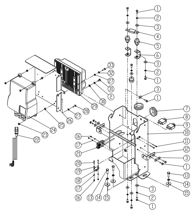
| DIA
NO. |
PART NUMBER | DESCRIPTION | SERIAL NUMBER | NO REQ’D |
| 1 | 1021616 | SCREW, HEX HEAD, M6×16 | 12 | |
| 2 | 1422616 | LOCK WASHER, M6 | 18 | |
| 3 | 1421618 | FLAT WASHER, M6×∮18×1.6 | 15 | |
| 4 | 8310480 | FUSE, 150A | 1 | |
| 5 | 8114705 | INSULATOR | 3 | |
| 6 | 8310422 | BRACKET, INSULATOR | 2 | |
| 7 | 8310133 | RUBBER GROMMET | 2 | |
| 8 | 8310740 | CIRCUIT BREAKER, 5A | 1 | |
| 9 | 8014068 | CIRCUIT BREAKER, 10A | 1 | |
| 10 | 8310450 | BRACKET, SCRUB HEAD LIFTING | 1 | |
| 11 | 1211330 | SCREW, PAN HEAD, M3×30 | 2 | |
| 12 | 8310425 | BRACKET | 2 | |
| 13 | 1021825 | BOLT, HEX HEAD, M8×25 | 5 | |
| 14 | 1422821 | LOCK WASHER, M8 | 5 | |
| 15 | 1421828 | FLAT WASHER, M8×∮28×2.5 | 5 | |
| 16 | 1123305 | LOCK NUT, M3 | 4 | |
| 17 | 1434300 | WASHER, TOOTH, M3 | 4 | |
| 18 | 8310423 | MICRO SWITCH | 1 | |
| 19 | 1421307 | FLAT WASHER, M3×∮7×0.5 | 2 | |
| 20 | 1211320 | SCREW, PAN HEAD, M3×20 | 2 | |
| 21 | 8310763 | OFF BOARD CHARGER SOCKET | 1 | |
|
22 |
8112030 | POWER CORD,US | 1 | |
| 8112040 | POWER CORD, EU | 1 | ||
| 8112050 | POWER CORD, JP | 1 | ||
| 8112060 | POWER CORD, CH | 1 | ||
| 8112070 | POWER CORD, UK | 1 | ||
| 23 | 1123507 | LOCK NUT, M5 | 4 | |
|
24 |
8210106A | BATTERY CHARGER, 25A | 1 | |
| 8350525 | BATTERY CHARGER,FOR TROJAN LEAD-ACID BATTERIES | 1 | ||
| 8350524 | BATTERY CHARGER,FOR DISCOVER LEAD-ACID BATTERIES | 1 | ||
| 25 | 1121505 | HEX NUT, M5 | 4 | |
| 26 | 8310452 | BRACKET, BATTERY CHARGER | 1 | |
| 27 | 1421510 | FLAT WASHER, M5×∮10×1.0 | 6 | |
| 28 | 1221520 | SCREW, HEX HEAD, M5×20 | 4 | |
| 29 | 8310790-G | MAIN CONTROLLER | 1 | |
| 30 | 1423612 | FLAT WASHER M6× ∮ 12×1, COPPER | 10 | |
| 31 | 1023612 | HEX BOLT M6 X 12, COPPER | 10 | |
| 32 | 1422513 | LOCK WASHER,M5 | 2 | |
| 33 | 1221525 | SCREW, HEX HEAD, M5×25 | 2 |
SEAT & DETERGENT SYSTEM GROUP

| DIA
NO. |
PART NUMBER | DESCRIPTION | SERIAL NUMBER | NO
REQ’D |
| 1 | 1221412 | SCREW, HEX HEAD, M4×12 | 4 | |
| 2 | 8133502 | CLAMP | 4 | |
| 3 | 8133501 | CARGO NET | 1 | |
| 4 | 1123810 | LOCK NUT, M8 | 5 | |
| 5 | 8310413 | SUPPORT, SEAT | 1 | |
| 6 | 8117007 | NYLON SPACER | 1 | |
| 7 | 8310415 | TORSION SPRING | 1 | |
| 8 | 8310414 | SLEEVE, ∮8.2×∮11×15 | 1 | |
| 9 | 1421816 | FLAT WASHER, M8×∮16×1.6 | 2 | |
| 10 | 1021830 | BOLT, HEX HEAD, M8×30 | 1 | |
| 11 | 8310411 | PLATE, SEAT MNTG | 1 | |
| 12 | 8310133 | RUBBER GROMMET | 1 | |
| 13 | 1512820 | SCREW, HEX SOCKET, M8×20 | 4 | |
| 14 | 8310402K | SEAT, KIT | 1 | |
| 15 | 1021616 | SCREW, HEX HEAD, M6×16 | 4 | |
| 16 | 1421618 | FLAT WASHER, M6× ∮ 18×1.6 | 4 | |
| 17 | 8310418 | CUP HOLDER | 1 | |
| 18 | 8310419 | BRACKET, CUP HOLDER | 1 | |
| 19 | 1123608 | LOCK NUT, M6 | 2 | |
| 20 | 8310460 | SPACER | 1 | |
| 21 | 8310463 | ADAPTOR, KEY | 1 | |
| 22 | 8310464 | INSERT, LOCK | 1 | |
| 23 | 8310461 | BOTTLE, DETERGENT | 1 | |
| 24 | 8310462 | CAP, BOTTLE | 1 | |
| 25 | 1021820 | BOLT, HEX HEAD, M8×20 | 2 | |
| 26 | 1422821 | LOCK WASHER, M8 | 2 | |
| 27 | 1421828 | FLAT WASHER, M8×∮28×2.5 | 5 | |
| 28 | 8310465 | BOX, DETERGENT BOTTLE | 1 | |
| 29 | 8310421 | BRACKET | 1 |
BATTERY GROUP
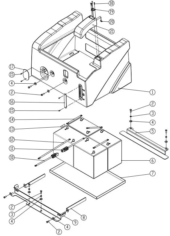
| DIA
NO. |
PART
NUMBER |
DESCRIPTION | SERIAL NUMBER | NO
REQ’D |
| 1 | 8310401 | BOX, BATTERY | 1 | |
| 2 | 1021820 | BOLT, HEX HEAD, M8×20 | 8 | |
| 3 | 1422821 | LOCK WASHER, M8 | 4 | |
| 4 | 1421824 | FLAT WASHER, M8×∮24×2.0 | 8 | |
| 5 | 8310131 | SUPPORT, BATTERY, REAR | 1 | |
| 6 | 8210105 | BATTERY, 6V 230AH | 4 | |
| 7 | 8310135 | TRAY, BATTERY | 1 | |
| 8 | 8310407 | PLATE | 2 | |
| 9 | 8310136 | SUPPORT, BATTERY, FRONT | 1 | |
| 10 | 8310736 | BATTERY CONNECT CABLE, RED | 1 | |
| 11 | 8310737 | BATTERY CONNECT CABLE, RED | 1 | |
| 12 | 8310733 | BATTERY CONNECT CABLE, BLACK | 1 | |
| 13 | 8114751 | JACKET, BATTERY TERMINAL,BLACK | 8 | |
| 14 | 8210141 | BATTERY CONNECT CABLE, BLACK | 3 | |
| 15 | 1221412 | SCREW, PAN HEAD, M4×12 | 4 | |
| 16 | 8310406 | COVER | 1 | |
| 17 | 8210114 | COVER | 1 | |
| 18 | 1662316 | RIVET, 3.2×16 | 4 | |
| 19 | 8310404 | HINGE ASSEMBLY | 1 | |
| 20 | 1421409 | FLAT WASHER, M4×∮9×0.8 | 4 | |
| 21 | 8310403 | COVER | 1 |
ORBITAL HEAD LIFTING GROUP

| DIA
NO. |
PART
NUMBER |
DESCRIPTION | SERIAL NUMBER | NO
REQ’D |
| 1 | 8340517 | SHOULDER BOLT, M8 | 1 | |
| 2 | 1123810 | LOCK NUT, M8 | 6 | |
| 3 | 8310303A | LINEAR ACTUATOR, KIT | 1 | |
| 4 | 8340133 | DAMPER,RUBBER | 2 | |
| 5 | 1032200 | BOLT, HEX HEAD, M12×100 | 2 | |
| 6 | 1421132 | FLAT WASHER, M13× ∮ 32×1.5 | 7 | |
| 7 | 8340134 | DAMPER,RUBBER | 4 | |
| 8 | 8340136 | SHOULDER, M10 | 1 | |
| 9 | 1021830 | BOLT, HEX HEAD, M8×30 | 4 | |
| 10 | 8340131 | BRACKET, GUIDE | 1 | |
| 11 | 1421824 | FLAT WASHER, M8× ∮ 24×2.0 | 2 | |
| 12 | 8321516 | THRUST WASHERS | 4 | |
| 13 | 8125415 | JOURNAL BEARING | 4 | |
| 14 | 8125414 | SLEEVEE, STAINLESS STEEL | 2 | |
| 15 | 8133151 | DAMPER, RUBBER | 3 | |
| 16 | 1435013 | WAVE WASHER, ∮ 13× ∮ 24×0.5 | 2 | |
| 17 | 8340120 | BRACKET, ORBTIAL HEAD LIFT | 1 | |
| 18 | 1123115 | NUT,LOCK, M12 | 2 | |
| 19 | 8340132 | DAMPER | 6 | |
| 20 | 8340137 | BRACKET, ACTUATOR | 1 | |
| 21 | 1421030 | FLAT WASHER, M10× ∮ 30×2.5 | 3 | |
| 22 | 1123012 | LOCK NUT, M10 | 3 | |
| 23 | 8340135 | SHOULDER BOLT, M10 | 2 | |
| 24 | 1123808 | METAL LOCK NUT, M8 | 2 |
ORBITAL HEAD GROUP

| DIA
NO. |
PART
NUMBER |
DESCRIPTION | SERIAL NUMBER | NO
REQ’D |
| 1 | 8340109 | MOTOR, 24VDC 560W2200RPM | 1 | |
| 2 | 8146110 | KEY,8x7x28 | 1 | |
| 3 | 1123012 | LOCKNUT, M10 | 20 | |
| 4 | 1421030 | FLAT WASHER M10x930x2.5 | 20 | |
| 5 | 8146520 | MOUNTING BRACKET | 2 | |
| 6 | 8146116 | ISOLATORS, M10x25 | 6 | |
| 7 | 1962016 | CL AMP | 2 | |
| 8 | 8146350 | TUBING,ID=12mmWIRE REINFORCED | 1 | |
| 9 | 8146511 | RIGHT-ANGLE TUBING FIT TING | 1 | |
| 10 | 1021830 | BOLT, HEX HEAD, M8x 30 | 3 | |
| 11 | 1421824 | FLAT WASHER, M8x624x2.0 | 6 | |
| 12 | 8115404 | LBEARING, JOURNAL | 3 | |
| 13 | 1435013 | WAVE WASHER 513x924x0.5 | 3 | |
| 14 | 8116009 | PROTECTIVE WHEEL | 3 | |
| 15 | 8310354 | KNOB, M10 | 4 | |
| 16 | 8340170 | BRACKET,SKIRT,LEFT | 1 | |
| 17 | 8340516 | KNOB, M10 | 4 | |
| 18 | 1123808 | LOCKNUT, M8 | 4 | |
| 19 | 1021080 | BOLT, HEX HEAD, M10x80 | 4 | |
| 20 | 1535610 | SET SCREW.M6x10 | 1 | |
| 21 | 8146107 | ISOLATORS, M10x25 | 4 | |
| 22 | 1421023 | FLAT WASHER M10x034x3.0 | 4 | |
| 23 | 1513020 | HEX SOCKET SCREW.M10x20 | 4 | |
| 24 | 8340502 | PAD DRIVER | 1 | |
| 25 | 1513616 | HEX SOCKET SCREW.M6x16 | 4 | |
| 26 | 8146205 | PL ATE | 1 | |
| 27 | 1513625 | HEX SOCKET SCREW.M6x 25 | 4 | |
| 28 | 8146303 | END CAP 3/8 | 2 | |
| 29 | 1123507 | T OCK NUTM5 | 6 | |
| 30 | 8340506 | PVC TUBING | 2 | |
| 31 | 8146305 | PL ASTIC CL AMP | 6 | |
| 32 | 8146301 | TEE FIT TING 3/8 | 1 | |
| 33 | 1521616 | HEX SOCKET BOLT,M6x16 | 2 | |
| 34 | 8146203 | BEARING HOUSING | 1 | |
| 35 | 1612608 | BALL BEAING 6008 | 1 | |
| 36 | 8146204 | BEARING HOUSING | 1 | |
| 37 | 8146201 | ECCENTRIC SHAFT | 1 | |
| 38 | 8146202 | ECCENTRIC | 1 | |
| 39 | 1513620 | HEX SOCKET SCREW.M6x20 | 4 | |
| 40 | 8340101 | MOTOR MOUNTING BRACKET | 1 | |
| 41 | 1421510 | FLAT WASHER, M5x910x1.0 | 6 | |
| 42 | 1221515 | SCREW M5x15 | 6 | |
| 43 | 8340180 | BRACKET,SKIRT,RIGHT | 1 | |
| 44 | 8310365 | SKIRT BLADE, LINATEX | 2 | |
| 45 | 8340515 | CL AMP STRIP | 2 | |
| 46 | 1514616 | Socket Round head,M6×16 | 10 |
SQUEEGEE GROUP

| DIA
NO. |
PART
NUMBER |
DESCRIPTION | SERIAL NUMBER | NO
REQ’D |
| 1 | 8310506 | PIN, ∮10×45 | 2 | |
| 2 | 8310590A | LINEAR, ACTUATOR, KIT | 1 | |
| 8310591A | LINEAR, ACTUATOR, KIT | 1 | ||
| 3 | 8310320 | PIN, COTTER | 2 | |
| 4 | 1121008 | HEX NUT, M10 | 2 | |
| 5 | 8310503 | BRACKET, SQUEEGEE | 1 | |
| 6 | 8310270 | VACUUM HOSE | 1 | |
| 7 | 1123115 | LOCK NUT, M12 | 1 | |
| 8 | 8310550 | CASTER, 2 INCH | 2 | |
| 9 | 8310501 | COMPRESSION SPRING, | 1 | |
| 10 | 8310504 | ARM, SQGE LIFTING | 1 | |
| 11 | 8310505 | FLEX BUSHING, TPU | 2 | |
| 12 | 8210525 | SHORT CLAMP ASSEMBLY | 1 | |
| 13 | 1221575 | SCREW, PAN HEAD, M5×75 | 1 | |
| 14 | 8118624 | SHAFT | 1 | |
| 15 | 8118623 | SPACER | 1 | |
| 16 | 1123507 | LOCK NUT, M5 | 1 | |
| 17 | 8311514 | CLAMP ASSEMBLY, RS26 | 1 | |
| 8310514 | CLAMP ASSEMBLY, RS28 / RS32 | 1 | ||
|
18 |
8311531 | REAR BLADE, LINATEX, RS26 | 1 | |
| 8310531 | REAR BLADE, LINATEX, RS28 / RS32 | 1 | ||
| 8311541 | REAR BLADE, PU, RS26, OPTION | 1 | ||
| 8310541 | REAR BLADE, PU,RS28/RS32, OPTION | 1 | ||
| 19 | 8311561 | SQUEEGEE HOSING, RS26 | 1 | |
| 8310561 | SQUEEGEE HOSING, RS28 / RS32 | 1 | ||
| 20 | 8311562 | RETAINER, SQUEEGEE, RS26 | 1 | |
| 8310562 | RETAINER, SQUEEGEE, RS28 / RS32 | 1 | ||
| 21 | 8311560 | SQUEEGEE ASSEMBLY, RS26 | 1 | |
| 8310560 | SQUEEGEE ASSEMBLY, RS28 / RS32 | 1 | ||
|
22 |
8311534 | FRONT BLADE, LINATEX, RS26 | 1 | |
| 8310534 | FRONT BLADE, LINATEX, RS28 / RS32 | 1 | ||
| 8311544 | FRONT BLADE, PU, RS26, OPTION | 1 | ||
| 8310544 | FRONT BLADE,PU,RS28/RS32, OPTION | 1 | ||
| 23 | 1021835 | BOLT, HEX HEAD, M8×35 | 2 | |
| 24 | 8210518 | KNOB, M8 | 4 | |
| 25 | 8115404 | SLEEVE, ∮ 8× ∮ 12.7×12.7 | 2 | |
| 26 | 8116009 | PROTECTIVE WHEEL | 2 | |
| 27 | 1421824 | FLAT WASHER, M8× ∮ 24×2 | 4 | |
| 28 | 1123810 | LOCK NUT, M8 | 2 | |
| 29 | 8210309 | PIN, COTTER | 2 | |
| 30 | 8310311 | PIN, ∮ 16×150 | 1 | |
| 31 | 8310508 | PIN, ∮ 12×100 | 1 | |
| 32 | 8310509 | EXTENSION SPRING | 2 | |
| 33 | 1031212 | BOLT, HEX HEAD, M12×120 | 1 | |
| 34 | 1421030 | FLAT WASHER, M10× ∮ 30×2.5 | 1 | |
| 35 | 1021060 | BOLT, HEX HEAD, M10×60 | 1 | |
| 36 | 8310507 | ADAPTER | 1 |
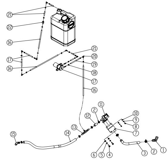
SOLUTION & DETERGENT SYSTEM
| DIA
NO. |
PART
NUMBER |
DESCRIPTION | SERIAL NUMBER | NO
REQ’D |
| 1 | 8119007 | ELBOW , G1/2 | 1 | |
| 2 | 1962016 | CLAMP 10-16MM | 6 | |
| 3 | 8340601 | TUBING , ID=13MM L=250MM | 1 | |
| 4 | 1021616 | BOLT, HEX HEAD , M6×16 | 2 | |
| 5 | 1422616 | LOCK WASHER , M6 | 2 | |
| 6 | 1421618 | FLAT WASHER , M6×∮18×1.6 | 2 | |
| 7 | 8340507 | SOLENOID MOUNTING BRACKET | 1 | |
| 8 | 1221412 | SCREW, PAN HEAD , M4×12 | 2 | |
| 9 | 1422411 | LOCK WASHER M4 | 2 | |
| 10 | 1421409 | FLAT WASHER , M4×∮9×0.8 | 2 | |
| 11 | 8119003 | SOLENOID VALVE , 24VDC | 1 | |
| 12 | 8340602 | TUBING , ID=13MM L=150MM | 1 | |
| 13 | 8600139 | T-JOINT | 1 | |
| 14 | 8340603 | TUBING , ID=13MM L=500MM | 1 | |
| 15 | 8146511 | ELBOW , G3/8 | 1 | |
| 16 | 8310905 | TUBING , ID=4MM L=330MM | 3 | |
| 17 | 8310930A | DETERGENT PUMP , KIT | 1 | |
| 18 | 1914080 | TIE , 3×80MM | 19 | |
| 19 | 8310910 | TUBING , ID=4MM L=100MM | 3 | |
| 20 | 8310467 | FITTING | 7 | |
| 21 | 8310909 | TUBING , ID=4MM L=30MM | 4 | |
| 22 | 8310466 | ONE WAY VALVE | 1 |
WEAR AND TEAR PARTS
| DIA
NO. |
PART
NUMBER |
DESCRIPTION | NO
REQ’D |
| 1 | 8310119 | 10″ WHEEL, PU TIRE | 2 |
| 2 | 8116009 | PROTECTIVE WHEEL | 2 |
| 3 | 8310362 | PROTECTIVE WHEEL | 1 |
|
4 |
8311531 | REAR BLADE, LINATEX, RS26 | 1 |
| 8310531 | REAR BLADE, LINATEX, RS28 / RS32 | 1 | |
|
5 |
8311534 | FRONT BLADE, LINATEX, RS26 | 1 |
| 8310534 | FRONT BLADE, LINATEX, RS28 / RS32 | 1 | |
|
6 |
9050013 | BRUSH, 13 INCH, RS26 | 2 |
| 9050014 | BRUSH, 14 INCH, RS28 | 2 | |
| 9050016 | BRUSH, 16 INCH, RS32 | 2 | |
|
7 |
9040013 | PAD DRIVER, 13 INCH, RS26 | 2 |
| 9040014 | PAD DRIVER, 14 INCH, RS28 | 2 | |
| 9040016 | PAD DRIVER, 16 INCH, RS32 | 2 |
WIRING DIAGRAM

- BAT: 4-6VDC batteries
- FU: 150A fuse
- CW: Off-board charger interlock switch
- BR1: Main controller circuit breaker, 5A
- KEY SW: Main power key switch
- AS: Alarm lamp switch
- LED2: Alarm lamp
- CH1: On-board battery charger
- CH2: Off-board battery charger port
- LED1: Work LED light
- BR2: Brake circuit breaker, 10A
- M3: Traction motor
- M1: Brush motor, left
- M6: Brush motor, right
- M2: Vacuum motor
- AP: Accelerator Pedal, sensor
- SL: Solution tank water level sensor
- RF: Recovery tank water level sensor
- RT: Reverse switch
- ST: Seat switch
- EG: Emergency stop switch
- M4: Scrub head lifting actuator
- M5: Squeegee lifting actuator
- BK: Brake coil
- DP: Detergent pump
- EW: Solution solenoid valve
- HN: Horn
More Information
CERTIFICATE OF QUALIFIED
- MODEL: ……………………..
- SERIAL NO.: ……………………..
- INSPECTOR: ……………………..
- DATE: ……………………..
ICE Company Limited
- TEL: (+86) 769 8186 9000
- FAX: (+86) 769 8186 3000