HYTRONIK HED7030/BT Bluetooth Dimmable LED Driver User Manual
Product Description
HED7030/BT is a Bluetooth dimmable LED driver, with maximum power output of 30W. It come with Switch-Dim interface by using Push switch (retractive switch) and of course Bluetooth dimming interface. The driver comes with an RJ12 terminal, ready to plug in a wide selection of motion sensors, ranging from HF to PIR, from low bay to high bay etc. It is ideal for direct projects or new luminaires design for lighting manufacturers. With Bluetooth wireless mesh networking, it makes communication between luminaires much easier without time-consuming hardwiring, which eventually saves costs for projects. Meanwhile, simple device setup and commissioning can be done via app
App Features
Quick setup mode & advanced setup mode
Floorplan feature to simplify project planning
Web app/platform for dedicated project management
Koolmesh Pro iPad version for on-site conguration
Grouping luminaires via mesh network
Scenes
Detailed motion sensor settings
Push switch conguration
Schedule to run scenes based on time and date
Astro timer (sunrise and sunset)
Staircase function (primary & secondary)
Internet-of-Things (IoT) featured
Device rmware update over-the-air (OTA)
Device social relations check
Bulk commissioning (copy and paste settings)
Power-on status (memory against power loss)
Ofine commissioning
Different permission levels via authority management
Network sharing via QR code or keycode
Remote control via gateway support HBGW01
Interoperability with Hytronik Bluetooth product portfolio
Compatible with EnOcean switch EWSSB/EWSDB
Continuous development in progress…
Hardware Features
Switch-Dim
![]() PWM 1KHz (1-100%)
PWM 1KHz (1-100%)
Bluetooth dimmable control
 Insulated terminal cover with cord restraint
 Standby power <0.5W
 Active PFC design
 Logarithmic Dimming
![]() Linear Dimming
Linear Dimming
![]() Congurable constant current (CC) output via DIP switch
Congurable constant current (CC) output via DIP switch
![]() Loop-in and loop-out terminals for efcient installation
Loop-in and loop-out terminals for efcient installation
![]() Open-circuit Protection
Open-circuit Protection
 Short-circuit Protection
 Overload Protection
![]() 5-year warranty, designed for long lifetime up to 50,000 hours
5-year warranty, designed for long lifetime up to 50,000 hours
Certain scenes which require external photocell can be achieved by using together with Hytronik Bluetooth sensors,such as HBIR29, HCD038/BT + sensor head etc
- Fully support
- EnOcean switch
- EWSSB/EWSDB
Output Configuration
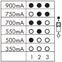
Warning: Please make sure the correct current is selected before starting the driver!
Technical Specifications
| Bluetooth Transceiver | |
| Operation frequency | 2.4 GHz – 2.483 GHz |
| Transmission power | 4 dBm |
| Range (Typical indoor) | 10~30m |
| Protoco | 5.0 SIG Mesh |
| Input | |
| Mains Voltage | 220~240VAC 50/60Hz |
| Mains Current | 0.17~0.16A |
| Power Factor | 0.9 |
| Max. Efficiency | 86% |
| Output | |
| Output Current | 350mA~900mA |
| Output Voltage | 10-57V |
| Uout Max. | 75V |
| Turn-on Time | <0.5s |
| Dimming Interface | Switch-Dim |
| Environment | |
| Operation Temp. | -20 ~ +50℃ |
| Case Temp. (Max.) | 80℃ |
| IP Rating | IP20 |
| Safety and EMC | |
| EN55015, EN61547, EN6100-2/3, | |
| EMC Standard | EN300328,EN301489-1/-17, |
| EN62479 | |
| Safety Standard | EN61347-1, EN61347-2-13 |
| Dielectric strength | Input→output: 3000VAC / 5mA /1min |
| Abnormal protection | Output short-circuit protection Overload ProtectionOpen-circuit Protection |
| Max. output power/current/voltage range | |
| HED7030/BT | 3.5-20W/350mA /10-57V5-29W/500mA /10-57V5.5-30W/550mA /10-55V7-30W/700mA /10-43V7.5-30W/750mA /10-40V9-23W/900mA /10-25V |
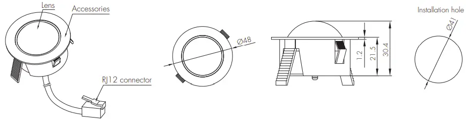
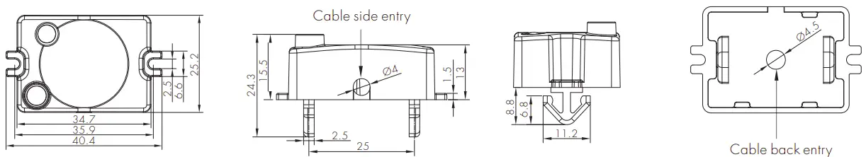
Mechanical Structure & Dimensions
Wire Preparation
To make or release the wire from the terminal, use a screwdriver to push down the button.
Wiring Diagram
Note: There is no need for any hardwirings on “push” terminal between one driver to another. The installer only needs to connect the push switches to the nearest driver to save labor and cost. The push switches can be assigned to control any Bluetooth driver through the app commissioning
Loading and In-rush Current
|
Model |
HEC7030/BF |
| In-rush Current (Imax.) | 38A |
| Pulse Time | 35 µs |
Circuit Breaker Information
|
Automatic circuit breaker type |
B16A | B10A | B13A | B20A | B25A |
| HED7030/BT | 54 | 34 | 43 | 67 | 84 |
The data above is calculated according to the formula: Maximum Amount = 16/(Pn/230). In order to provide a more reliable reference in real application, the data have been revised to take 60% of the number calculated, i.e. 16/(Pn/230) x 60%. Please kindly take note that the calculation is based on ABB circuit breaker series S200. Actual values may differ due to different types of circuit breaker used and installation environment.
Performance Characteristics
Typical Efficiency vs Load
Typical Power Factor vs Load
Dimming Characteristics
Dim Level
Technical Specifications for Sensor Heads
| PIR Sensor Properties | |
| Sensor principle | PIR detection |
| Operating voltage | 5VDC |
|
Detection range * |
HIR05 & HIR05/FM & HIR05/E & HIR07Max installation height:3mMax detection range:6m (diameter) HIR11Max installation height:15m (forklift)12m (single person) Max detection range: 24m (diameter)HIR12Max installation height:15m (forklift)12m (single person) Max detection range: 18m * 6m (L * W) |
| HF Sensor Properties | |
| Sensor principle | High Frequency (microwave) |
| Operating voltage | 5VDC |
| Operation frequency | 5.8GHz +/- 75MHz |
| Transmission power | <0.2mW |
| Detection range * | SAM20 / SAM21 / SAM22Max installation height:3mMax detection range:12m (diameter) SAM23Max installation height:12mMax detection range:16m (diameter) |
The detection range is heavily influenced by sensor placement (angle) and different walking paces. It may be reduced under certain conditions.
- A. HIR05 PIR sensor head The cable length is around 65cm
- B. HIR05/E PIR sensor head The cable length is around 65cm
- C. HIR05/FM PIR sensor head The cable length is around 65cm.
- D. HIR07 PIR sensor head Photocell Advance The cable length is around 30cm
- E. HIR11/S PIR sensor head Surface mounting For high bay application IP65 (facia / lens part) The cable length is around 65cm
- F. HIR11/F PIR sensor head Flush mounting For high bay application IP65 (facia / lens part) The cable length is around 65cm.
- G. HIR11/C PIR sensor head Screw to the luminaire by conduit For high bay application IP65 (facia / lens part) The cable length is around 65cm.
- F. HIR12 PIR sensor head For high bay application IP65 (facia / lens part) The cable length is around 65cm
Installation for HIR1
Thickness: 0.8mm – 1.6mm
We suggest that the metal plate thickness to be 0.8mm – 1.6mm to ensure perfect focal length for the PIR lens.
- SAM20 HF sensor head Photocell AdvanceTM The cable length is around 30cm.
- SAM21 HF sensor head IP65 The cable length is around 65cm.
- SAM22 HF sensor head Flush mount The cable length is around 65cm
- SAM23 HF sensor head Photocell advance For highbay application The cable length is around 30cm.
Detection Pattern
Ceiling mounted detection pattern (m)
SAM23
Ceiling mounted detection pattern (m)
SAM20 / SAM21 / SAM22
Subject to change without notice.
HIR05 & HIR05/FM & HIR05/E & HIR07b
HIR12
| HIR11 (High-bay) | |||||
| HIR11: High-bay lens detection pattern for forklift @ Ta = 20OC (Recommended installation height 10m-15m) | |||||
| A: Tangential movement
h = max.15m insensitive sensitive |
B: Radial movement
h = max.15m insensitive sensitive |
Mount height | Tangential (A) | Radial (B) | |
| 10m | max 380m2 (Ø = 22m) | max 201m2 (Ø = 16m) | |||
| 11m | max 452m2 (Ø = 24m) | max 201m2 (Ø = 16m) | |||
| 12m | max 452m2 (Ø = 24m) | max 201m2 (Ø = 16m) | |||
| 13m | max 452m2 (Ø = 24m) | max 177m2 (Ø = 15m) | |||
| 14m | max 452m2 (Ø = 24m) | max 133m2 (Ø = 13m) | |||
| 15m | max 452m2 (Ø = 24m) | max 113m2 (Ø = 12m) | |||
|
HIR11: High-bay lens detection pattern for single person @ Ta = 20 C(Recommended installation height 2.5m-12m) |
|||||
A: Tangential movement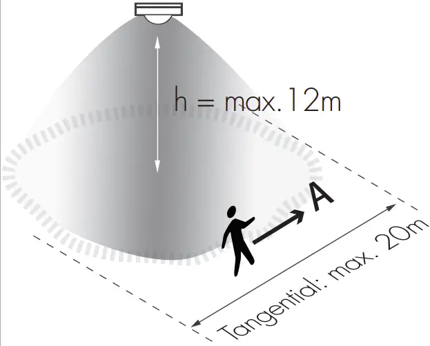
h = max.12m insensitive sensitive |
B: Radial movement
h = max.12m insensitive sensitive |
Mount height | Tangential (A) | Radial (B) | |
| 2.5m | max 50m2 (Ø = 8m) | max 7m2 (Ø = 3m) | |||
| 6m | max 104m2 (Ø = 11.5m) | max 7m2 (Ø = 3m) | |||
| 8m | max 154m2 (Ø = 14m) | max 7m2 (Ø = 3m) | |||
| 10m | max 227m2 (Ø = 17m) | max 7m2 (Ø = 3m) | |||
| 11m | max 269m2 (Ø = 18.5m) | max 7m2 (Ø = 3m) | |||
| 12m | max 314m2 (Ø = 20m) | max 7m2 (Ø = 3m) | |||
Dimming Interface Operation Notes
Switch-Dim
The provided Switch-Dim interface allows for a simple dimming method using commercially available non latching (momentary) wall switches. Up to 64 LED drivers maybe connected to one switch. Detailed Push switch congurations can be set on Koolmesh app.
| Switch Function | Action | Descriptions |
|
Push switch |
Short press (<1 second)* Short press has to be longer than 0.1s, or it will be invalid. |
|
| Double push |
|
|
| Long press (≥1 second) |
|
|
| Simulate sensor | / |
|
Additional Information / Documents
- Regarding precautions for LED driver installation and operation, please kindly refer to www.hytronik.com/download ->knowledge ->LED Drivers – Precautions for Product Installation and Operation
- To learn more about detailed product features/functions, please refer t www.hytronik.com/download->knowledge ->Introduction of App Scenes and Product Functions
- Regarding precautions for Bluetooth product installation and operation, please kindly refer to www.hytronik.com/download ->knowledge ->Bluetooth Products – Precautions for Product Installation and Operation
- Data sheet is subject to change without notice. Please always refer to the most recent release on www.hytronik.com/products/bluetooth technology ->Bluetooth Drivers
- Regarding Hytronik standard guarantee policy, please refer to www.hytronik.com/download ->knowledge ->Hytronik Standard Guarantee Policy