HYTRONIK HBEM01 Constant Current Self Test
Contents
HBEM01 Constant Current, Self-Test
Product Description
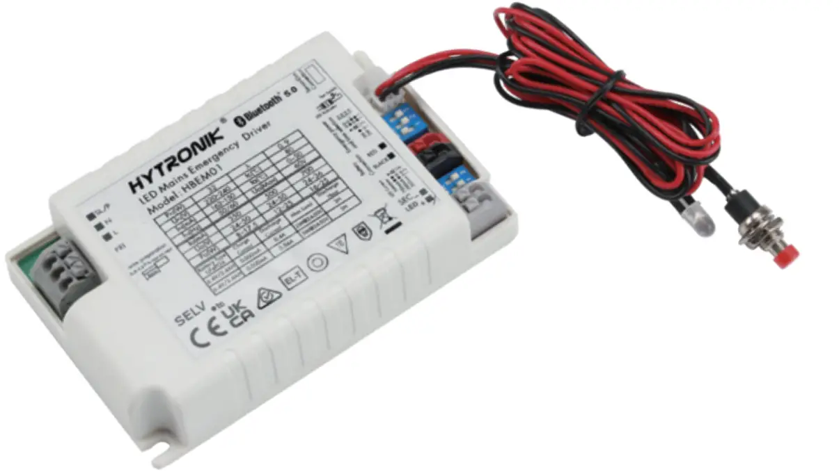
HBEM01 is a combined Bluetooth LED driver & emergency control gear with RJ12 connection for optional sensor heads SAM20, SAM21, SAM22, SAM22/FM, SAM23, HIR05, HIR05/FM, HIR05/AA, HIR07, HIR11 series, HIR12, HIR63 series. When the sensor head is not attached to, HBEM01 alone is a normal Bluetooth emergency driver with self-test function. When the sensor head is attached to, HBEM01 is a normal Blutooth emergency driver with motion, daylight sensor and self-test function. With gateway HBGW01 ready, user can generate emergency testing report through our  app. HBEM01 can also conduct monthly or annually testing automatically and user can get email notification as soon as fault is detected. Meanwhile, simple device setup and commissioning can be done via app
App Features
 |
Quick setup mode & advanced setup mode |
 |
Web app/platform for project deployment & data analysis |
 |
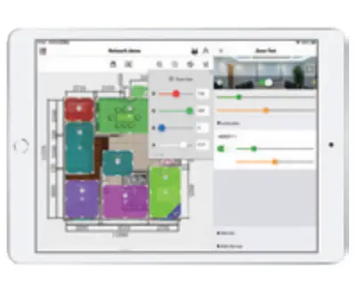
Koolmesh Pro app on iPad for on-site conguration |
|
|
Floorplan feature to simplify project planning |
 |
Emergency report generation and diagnosis |
 |
One-key device replacement |
 |
Device social relations check |
 |
Staircase function (primary & secondary) |
 |
Remote control via gateway support HBGW01 |
 |
Grouping luminaires via mesh network |
 |
Scenes |
 |
Dusk/Dawn photocell (Twilight function) |
 |
Tri-level control |
 |
Daylight harvest |
 |
Circadian rhythm (Human centric lighting) |
 |
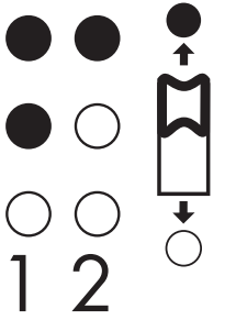
Push switch conguration |
 |
Detailed motion sensor settings |
 |
Schedule |
 |
Astro timer (sunrise and sunset) |
 |
Power-on status (memory against power loss) |
 |
Offline commissioning |
 |
Bulk commissioning (copy and paste settings) |
 |
Different permission levels via authority management |
 |
Network sharing via QR code or keycode |
 |
Interoperability with Hytronik Bluetooth product portfolio |
 |
Compatible with EnOcean BLE switches |
 |
Internet-of-Things (IoT) featured |
 |
Device rmware update over-the-air (OTA) |
 |
Continuous development in progress… |

Hardware Features
 |
Switch-Dim |
 |
Photocell Advance |
 |
Active PFC design |
 |
Open-circuit Protection |
 |
hort-circuit Protection |
 |
Overload Protection |
 |
5-year warranty, designed for long lifetime up to 50,000 hours |
Emergency Features
 |
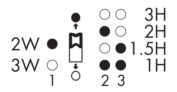
Emergency wattage: 2W/3W |
 |
Emergency working mode:
|
 |
Monthly/Annually Automatic Testing with report generation |
 |
Battery status check via Kool mesh app |
 |
Automatic email notication when fault is detected |
 |
Retrievable usage data and report history |
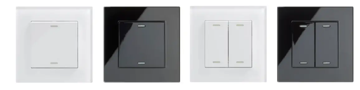
Fully support EnOcean self-powered switch module PTM215B
(HBES01/W & HBES01/B)
Technical Specifications
|
Bluetooth Transceiver |
|
| Operation frequency | 2.4 GHz- 2.483 GHz |
| Transmission power | 4 dBm |
| Range (Typical indoor) | l0~30m |
| Protocol |  5 . 0 SIG Mesh 5 . 0 SIG Mesh |
|
|
|
 |
 |
 |
|
|
Smartphone app for both iOS & Android platform |
|
 |
 |
|
Koolmesh Pro app for iPad |
|
 |
 |
|
Web app/platform: www.iot.koolmesh.com |
|
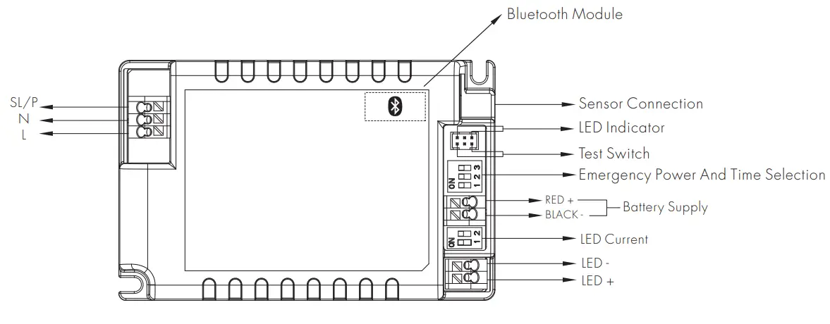
| LED Current Selection
|
Emergency power and time selection
|
|
Model No. HBEM01 |
|
|
Mains voltage |
220~240VAC 50/60Hz |
| Mains current |
0.162~0.15A |
| Max. driver output power |
25W |
| Max. emergency output power | 3W |
| Output wattage / LED current / voltage | 8-17.5W / 350mA / 24-50V 12-25W / 500mA / 24-50V 16-25W / 700mA / 24-36V |
| Efficiency | max. 85% |
| Output voltage(U-out Max.) | 60V |
| Power factor | >0.9 |
| Operation temperature | 0~+50℃ |
| Storage temperature | -10~+35℃ |
| Battery charge current | 0 – 500mA |
| Battery pack | BPC83, BPC84 |
| Battery Type (LiFePO4) / Discharge current / Max. load / Discharge hour | BPC83/BPC84: 6.4V, 3.4AH / 0.4A, 2W@24 – 50V / 180min BPC83/BPC84: 6.4V, 3.4AH / 0.56A, 3W@24 – 50V / 180min |
| Charge period | 16h |
| Max. case temp. | 80℃ |
| Abnormal protection | Output short-circuit protection, Overload Protection, Open-circuit Protection |
| Battery abnormal protection | Short circuit protection |
| Reverse connection protection | |
| Deep discharge | |
| EMC standard | EN55015, EN61547, EN61000-3-2, EN61000-3-3, EN300328; EN301489-17 |
| Safety standard | EN61347-1, EN62493, EN61347-2-7, EN62034, IEC62133 |
| Certifications | CE, UKCA, RCM, ROHS |
| IP grade | IP20 |
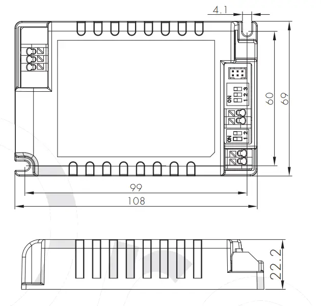
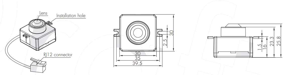
Mechanical Structure & Dimensions
HBEM01
Wire Preparation
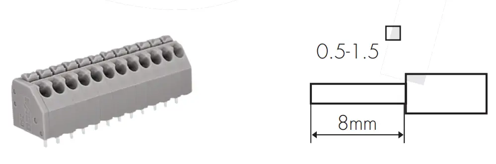
Solid or Stranded wire type 0.5 – 1.5mm2
To make or release the wire from the terminal, use a screwdriver to push down the button.
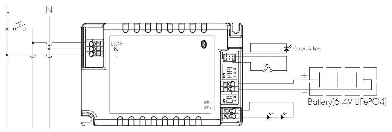
Wiring Diagram
With sensor head 
Loading and In-rush Current
|
Model |
HBEM01 |
|
In-rush Current (Imax.) |
21A |
| Pulse Time |
80 s |
Circuit Breaker Information
| Automatic circuit breaker type | B16A | B10A | B13A | B20A | B25A |
| HBEM01 | 114 | 72 | 92 | 142 | 178 |
Calculation uses typical values from ABB series S200 as a reference. E.g. Maximum amount =16/(Pn/230). We recommend to use no more than 60% of the data as the actual max. number of drivers in real application. Actual values may differ due to used circuit breaker types and installation environment.
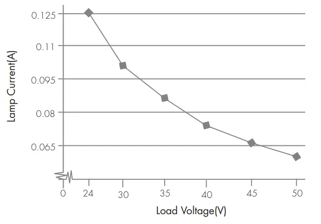
Performance Characteristics

2W Output Current vs voltage

3W Output Current vs Voltage
Normal Mode
It is the mode in which mains supply is available, with the battery charged or charging. In this mode, HBEM01 is a dimmable emergency driver, with ability to create scenes and controllable by motion sensor, Push switch and app.
Emergency Mode
It is the mode in which mains supply has failed and whilst the control gear is powered by the battery until deep discharge point. In this mode, HBEM01 is unable to be controlled by motion sensor, Push switch and app. However, some emergency parameter scan still be configured via the app, such as time scheduled for self-test, dur HYTRONIK HBEM01 Constant Current Self Test Instruction Maculation for extended emergency mode etc.
Rest Mode
It is the mode in which the luminaire is intentionally off whilst the control gear is powered by the battery. To enter this mode, the prerequisite is that there is no mains supply. In this mode, the luminaire will be turned off automatically and HBEM01 is powered by the battery. If the luminaire is forced to turn on in this mode, HBEM01 will then be adjusted to emergency mode. When mains supply is recovered, HBEM01 will return to normal mode.
Inhibit Mode
It is the mode in which HBEM01 is powered from the mains but prevented from going into emergency mode in the event of mains failure. Please enter this mode only in special applications whereby emergency function is not needed, such as when electrician needs to cut off power supply when doing examination and maintenance work for HBEM01.
Extended Emergency Mode
It is the mode in which the control gear continues to operate the lamp in the same way as in emergency mode for the programmed prolong time after the restoration of the mains supply. When this mode is enabled, HBEM01 will remain in emergency mode even when mains supply is recovered. In this mode, the user has to set the time extended for emergency mode; when the time extended elapses, HBEM01 will then return to normal mode.
Self test (Monthly)
HBEM01 carries out routine test on emergency lighting based on pre-programmed time via the app or after receiving manual commands from the app. During the self test process, tests for load connections (such as open circuit, short-circuit) and battery connections (such as open circuit, short-circuit, polarity reversal etc.) will be carried out.
Self test (Annually)
The test is carried out mainly to check the battery level. The user has to make sure that the battery for HBEM01 is fully charged before HBEM01 carries out annual test. Also, the battery lifetime statistics will be analysed and displayed on a chart basis.
LED Diagnostics
| Indicator Colour | Status |
Meaning |
|
GREEN SOLID |
Device OK |
All OK, AC power is present. Battery is connected & charging |
|
GREEN FAST FLASH |
Monthly test/Functionality test |
AC power is present. Monthly test in progress |
|
GREEN VERY SLOW FLASH |
Annual test/Duration test |
Annual test are being carried out |
|
RED SOLID |
Emergency LED fault |
Emergency LED is open circuit, short circuit or has otherwise failed in some way,. Fault can indicate the live status or the result of a test |
|
RED SLOW FLASH |
Battery fault | Battery failure (Battery failed the duration or functional test, battery appears to be defective, battery has incorrect voltage). |
| RED /GREEN OFF | No power available |
AC power is lost, unit in emergency mode |
*If you want to see the diagnostic report, please go to the APP or web platform to see the full report and analysis
Note: Before powering on, please plug in the sensor head and then plug in the battery, otherwise the sensor is disabled. Remedy: Only after the APP is reset and re-connected to the network can the sensor head be re-identified.
Battery Pack Options
|
Package |
Picture | Spec. | Size (mm) | Duration | Recharge Time |
Accessories |
|
BPC84 |
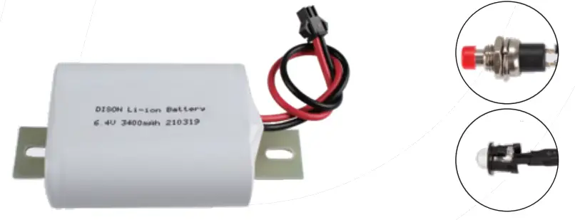 |
LiFePO4, |
170x30x27 | >3h @3W >3h @2W |
16h |
Battery bracket, |
|
BPC84 |
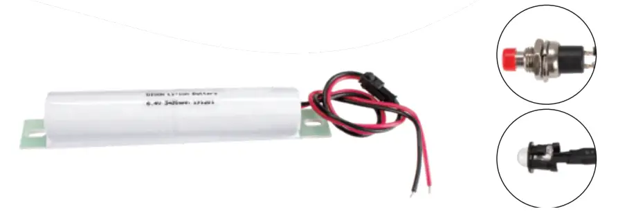 |
LiFePO4, |
170x30x27 | >3h @3W >3h @2W |
16h | Battery bracket, LED indicator, Test switch |
Please kindly note that the optimal storage temperature should be 22°C to28°C.
The relative humidity (RH) for battery storage should be 45% to 85%.
Keep the battery wires unconnected if the battery is intended to be stored for more than 3 months.
The maximum battery cycles under 55°C should not exceed 80 times.
Please kindly charge battery for 24 hours before using.
Do not short-circuit the battery pack.
In case of a short circuit the battery protection opens the connection to the driver and the output is therefore free of voltage. At this time, it will falsely report battery failure. The output will be reactivated again when the short circuit is removed.
Technical Specifications for Sensor Heads
| PIR Sensor Properties | ||
| Sensor principle | PIR detection | |
| Operating voltage | 5VDC | |
| Detection range | HIR05 & HIR05/FM HIR05/AA & & HIR07 |
Max installation height: 3m; Max detection range: 6m (diameter) |
| HIR11 | Max installation height: 15m (forklift); 12m (single person); Max detection range: 24m (diameter) | |
| HIR12 | Max installation height: 15m (forklift); 12m (single person); Max detection range: 18m*6m (L*W) | |
| HIR63 | Max installation height: 3m; Max detection range: 12m (diameter) | |
| HIR63/R | Max installation height: 12m (forklift); 8m (single person); Max detection range: 14m (diameter) | |
| HF Sensor Properties | ||
| Sensor principle | High Frequency (microwave) | |
| Operating voltage | 5VDC | |
| Operation frequency | 5.8GHz +/- 75MHz | |
| Transmission power | <0.2mW | |
| Detection range * | SAM20 & SAM21 SAM22 & SAM22/AA |
Max installation height: 3m; Max detection range: 12m (diameter) |
| SAM23 | Max installation height: 15m (forklift); 12m (single person); Max detection range: 20m (diameter) | |
* The detection range is heavily infiuenced by sensor placement (angle) and different walking paces. It may be reduced under certain conditions.
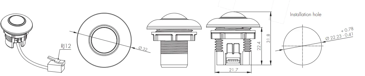
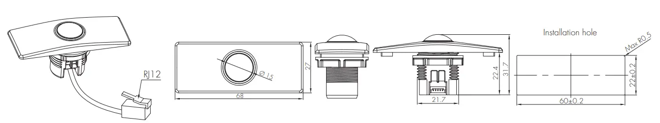
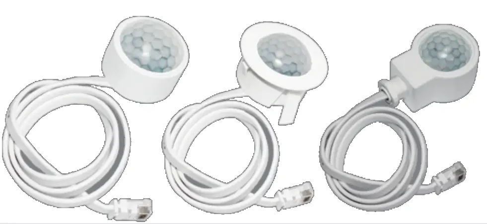
PIR & microwave sensor heads
The range of PIR and microwave sensor heads below offers powerful number of Plug ’n ’Play feature options to expand the fixability of luminaires design. This approach to luminaire design reduces space requirements and component costs whilst simplifying production.
A. HIR05
PIR sensor head The cable length is around 65cm.
B. HIR05/FM
PIR sensor head The cable length is around 65cm.

C. HIR05/AA
PIR sensor head Adjustable angle The cable length is around 65cm.
D. HIR07
PIR sensor head Photocell Advance The cable length is around 30cm.
E. HIR11/S
PIR sensor head Surface mounting For highbay application IP65 (facia / lens part) The cable length is around 65cm.

F. HIR11/F
PIR sensor head Flush mounting For highbay application IP65 (facia / lens part) The cable length is around 65cm.
G. HIR11/C
PIR sensor head Screw to the luminaire by conduit For highbay application IP65 (facia / lens part) The cable length is around 65cm.
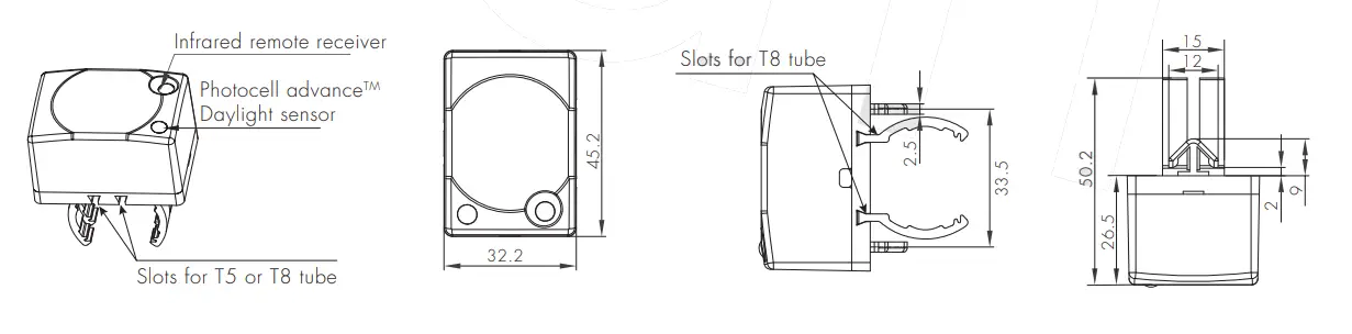
H. HIR12
PIR sensor head For highbay application IP65 (facia / lens part) The cable length is around 65cm.
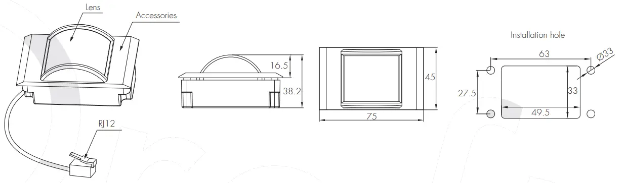
Installation for HIR12

We suggest that the metal plate thickness to be 0.8mm – 1.6mm to ensure perfect focal length for the PIR lens.
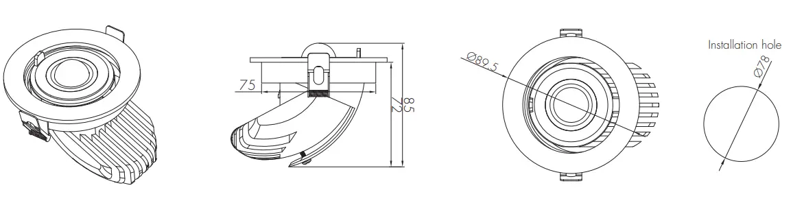
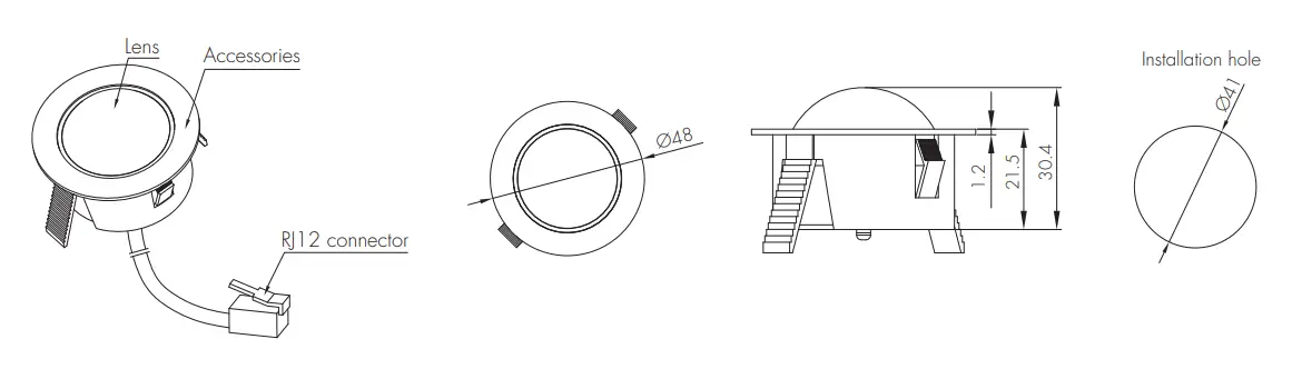
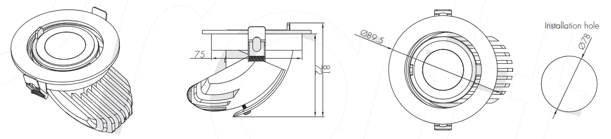
I. HIR63
PIR sensor head The cable length is around 65cm.
J. HIR63 with HA04
PIR sensor head The cable length is around 65cm.

K. HIR63 with HA05
PIR sensor head The cable length is around 65cm.
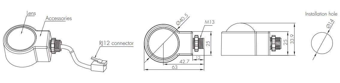
L. HIR63/R
PIR sensor head IP65 (facia / lens part) The cable length is around 65cm.

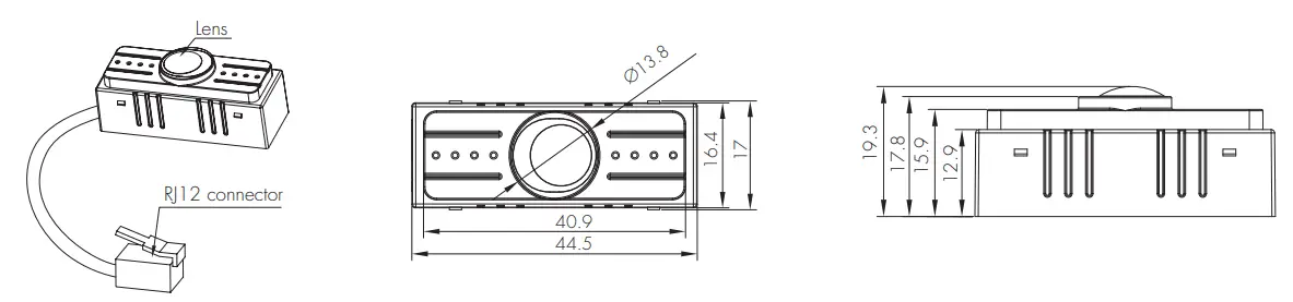
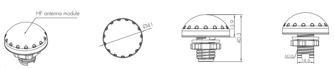
M. SAM20
HF sensor head Photocell Advance TM The cable length is around 30cm.
N. SAM21
HF sensor head IP65 The cable length is around 65cm.
O. SAM22
HF sensor head Flush mount The cable length is around 65cm.
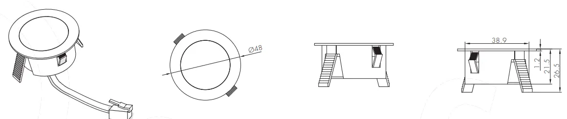
P. SAM22/AA
HF sensor head Adjustable angle The cable length is around 65cm.
Q. SAM23
HF sensor head Photocell advance For highbay application The cable length is around 30cm.
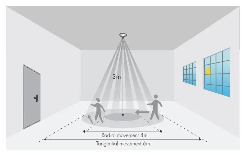
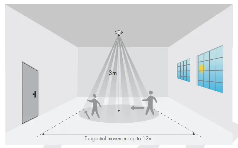
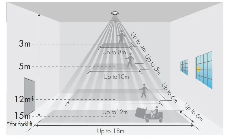
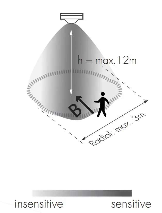
Detection Pattern
SAM23

SAM20 & SAM21 & SAM22 & SAM22/AA

HIR05 & HIR05/FM & HIR05/AA & HIR07
HIR63
HIR12
HIR63/R
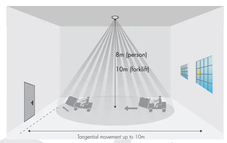
*The detection patterns are based upon 5km/h movement speed.
|
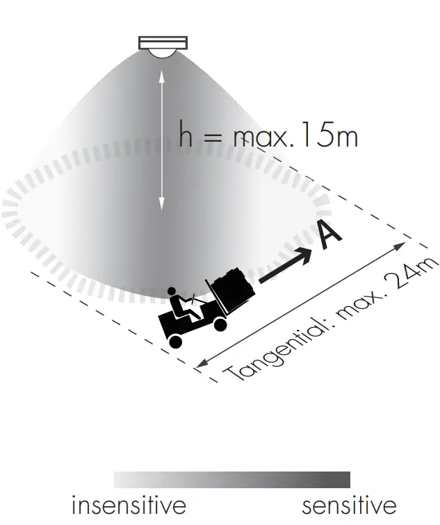
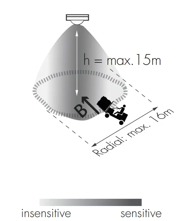
HIR11 Series (High-bay) |
|||||
 |
HIR11series: High-bay lens detection pattern for forklift @ Ta = 20OC (Recommended installation height 10m-15m) | ||||
| A: Tangential movement
|
B: Radial movement
|
Mount height |
Tangential (A) |
Radial (B) |
|
|
10m |
max 380m2 (Ø = 22m) | max 201m2 (Ø = 16m) | |||
| 11m | max 452m2 (Ø = 24m) |
max 201m2 (Ø = 16m) |
|||
|
12m |
max 452m2 (Ø = 24m) | max 201m2 (Ø = 16m) | |||
| 13m | max 452m2 (Ø = 24m) |
max 177m2 (Ø = 15m) |
|||
|
14m |
max 452m2 (Ø = 24m) | max 133m2 (Ø = 13m) | |||
| 15m | max 452m2 (Ø = 24m) |
max 113m2 (Ø = 12m) |
|||
 |
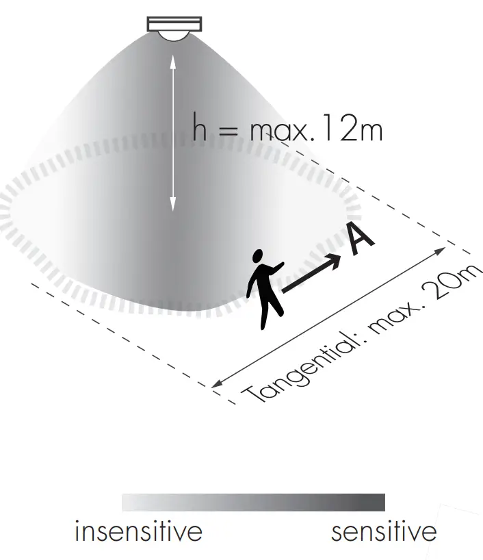
HIR11 series: High-bay lens detection pattern for single person @ Ta =20 C (Recommended installation height 2.5m-12m) |
||||
|
A: Tangential movement |
B: Radial movement |
Mount height | Tangential (A) | Radial (B) | |
| 2.5m | max 50m2 (Ø = 8m) | max 7m2 (Ø = 3m) | |||
| 6m | max 104m2 (Ø = 11.5m) | max 7m2 (Ø = 3m) | |||
| 8m | max 154m2 (Ø = 14m) | max 7m2 (Ø = 3m) | |||
| 10m | max 227m2 (Ø = 17m) | max 7m2 (Ø = 3m) | |||
| 11m | max 269m2 (Ø = 18.5m) | max 7m2 (Ø = 3m) | |||
| 12m | max 314m2 (Ø = 20m) | max 7m2 (Ø = 3m) | |||
Additional Information / Documents
- Regarding precautions for Bluetooth product installation and operation, please kindly refer to www.hytronik.com/download/knowledge ->Bluetooth Products – Precautions for Product Installation and Operation
- Regarding precautions for LED driver installation and operation, please kindly refer to www.hytronik.com/download/knowledge ->LED Drivers – Precautions for Product Installation and Operation
- Regarding precautions and usage for LiFePO4 battery, please kindly refer to www.hytronik.com/download/knowledge ->LiFePO4 Battery – Precautions and Usage
- Data sheet is subject to change without notice. Please always refer to the most recent release on www.hytronik.com/products/bluetooth technology ->Bluetooth Emergency Driver/Inverter
- Regarding Hytronik standard guarantee policy, please refer to www.hytronik.com/download/knowledge ->Hytronik Standard Guarantee Policy