![]() ASSEMBLY/OPERATING INSTRUCTIONS
ASSEMBLY/OPERATING INSTRUCTIONS
WITH PARTS LIST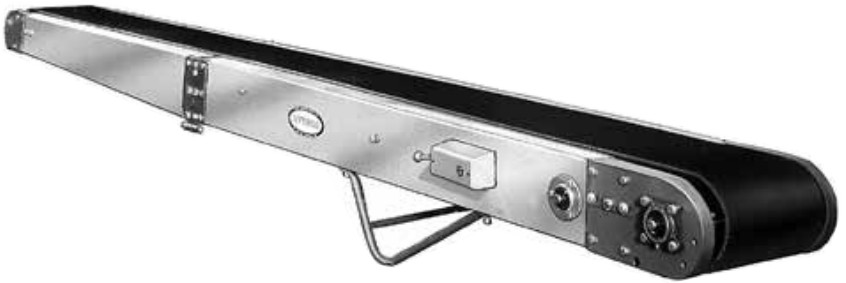 Bulletin No. 703
MODEL
R
April 2017
(Supercedes July 2007)
Contents
R Portable Compact Belt Conveyor
| Ambient Temperature Degrees F | SAE | ISO |
| 20-40 | 20 | 46 or 68 |
| 40-100 | 30 | 100 |
| 100-120 | 40 | 150 |
MODEL “R” — ALUMINUM PORTABLE “COMPACT” BELT CONVEYOR
Remove conveyor from wood crate. Model “R” is completely assembled in its full length.
TO OPERATE—Be sure the belt is free before running. Check for any loose, foreign pieces which could have dropped into conveyor during shipping. Plug into electrical outlet, making sure correct voltage and power is available.
MOTOR— The standard motor is 115/230 Volt-Single Phase. It will be wired for 115 volts unless otherwise specified. Avoid weak lighting circuits and long extension cords. Heavy power wiring will insure better motor performance and enable conveyor to carry the rated loads.
TO LUBRICATE—The drive chain is pre-lubricated from the manufacturer by a hot dipping process that ensures total lubrication of all components. However, continued proper lubrication will greatly extend the useful life of every drive chain.
Drive Chain lubrication serves several purposes including: protecting against wear of the pin-bushing joint, lubricating chain-sprocket contact surfaces, and preventing rust or corrosion.
For normal operating environments, lubricate every 2080 hours of operation or every 6 months, whichever comes first. Lubricate with a good grade of non-detergent petroleum or synthetic lubricant (i.e., Mobile 1 Synthetic). For best results, always use a brush to generously lubricate the chain. The proper viscosity of lubricant greatly affects its ability to flow into the internal areas of the chain. Refer to the table below for the proper viscosity of lubricant for your application.
The drive chain’s lubrication requirement is greatly affected by the operating conditions. For harsh conditions such as damp environments, dusty environments, excessive speeds, or elevated temperatures, it is best to lubricate more frequently. It may be best, under these conditions, to develop a custom lubrication schedule for your specific application. A custom lubrication schedule may be developed by inspecting the drive chain on regular time intervals for sufficient lubrication. Once the time interval is determined at which the chain is not sufficiently lubricated, lubricate it and schedule the future lubrication intervals accordingly.
DRIVE ADJUSTMENT—To insure maximum rated load capacity to drive pulley, check V-belt and roller chain tension. Tension in V-belt from the motor to first 2-step pulley is increased by tightening eye bolt to motor guard. Second V-belt is tightened by loosening jack shaft end bolts on outside of conveyor bed and moved on threaded locating shaft.
First roller chain is tightened in the same manner. Be sure end bolts are tight after adjusting. The last roller chain is tightened by moving drive pulley out. Bearings are mounted in slotted holes.
BELT TENSION—To insure maximum rated load capacity on conveyor belt, maintain enough tension so that drive pulley will not slip under belt when carrying full load. Screw take-ups on tail pulley will tighten belt. Because of climactic conditions or after lengthy service, it may be necessary to shorten conveyor belt. A short additional piece of belt (called a “Dutchman”) is inserted and can be removed when the limit of screw take-up is reached. If more take-up is required, cut and re-lace conveyor belt to maintain proper belt tension.
TRACKING THE BELT—All conveyors are assembled and run at the factory, and the belt is tracked before shipment. In the event the belt does not track, follow these instructions: Check conveyor bed section for alignment (no twist or bend). Check drive pulley and tail pulley to insure squareness with conveyor bed. Drive pulley shaft bearings can be moved. Slotted mounting holes are provided in drive plates.
Take-up screw adjusts tail pulley. For belt running in forward direction (toward drive pulley), if belt runs to the left, move side of tail pulley out (away from the drive end). Use screw take-up. Move opposite side when belt runs to the right. For belt running in reverse direction (away from drive pulley), if belt runs to the left, move right side of snub idler (located directly behind drive pulley) back (away from drive). When belt is running off to the right, move opposite side.
TRACKING LOWER POWERED FEEDER SECTION—Follow same procedure as main conveyor belt. Drive pulley is the 5 in. pulley with chain drive from main conveyor. Snub idler is mounted inside feeder section bed.
Use code HYPMANUAL for free shipping
on your first order at HytrolParts.com
Model “R” Parts Drawing
 “Building Relationships One Conveyor Part at a Time”
Model “R” Parts List
 RECOMMENDED SPARE PARTS LIST HIGHLIGHTED IN GRAY
| Ref. No. | Part No. | Description |
| 1 — — 2 3 |
— 030.2016 030.4014 032.103 034.110 |
Motor—C-Face, Foot Mounted 1/2 HP 115/230VAC-1 Ph—60 Hz TENV 1 HP 115/230VAC-1 Ph—60 Hz TEFC Reversing Drum Switch (1 Ph.—NEMA 1) Power Cord—12GA, 5 Conductor |
| 4 5 6 7 8 |
034.101 035.101 035.102 B-00251 B-02331 |
Power Cord w/Wall Plug #034.201 (20 ft. Lg.) Cable Connector—Straight Cable Connector—90 Degree Motor Guard Assembly Motor Mount Assembly |
| 9 10 11 12 13 |
B-01542-018 020.100 066.107 B-09764 B-00206 |
Motor Mount Bar Motor Sheave—2 in. O.D. x 5/8 in. Bore V-Belt (4L290) V-Pulley Assembly—2-Step V-Pulley—2-Ste |
| 14 15 16 17 18 |
011.103 B-00210-018 098.158 049.304 066.106 |
Bearing—1-5/8 in. O.D. x 3/4 in. Bore Jackshaft—3/4 in. Dia. x 12 in. Long Spacer—3/4 in. I.D. x 1 in. O.D. x 1/2 in. Long External Retaining Ring—3/4 in. Dia. Shaft V-Belt (4L280) |
| 19 20 21 22 23 |
B-01750 B-00212 026.1275 090.300 098.157 |
V-Pulley & Sprocket Assembly V-Pulley Only Sprocket—40B17 x 1-7/8 in. Bore Drive Lock Pin—1/4 in. Dia. x 1/2 in. Long Spacer—3/4 in. I.D. x 1 in. O.D. x 1/8 in. Long |
| 24 25 26 27 28 |
044.105 041-300 029.100 029.200 B-01286 |
Take-Up Rod—3/8-16 x 20-1/2 in. Long Hex Jam Nut—Heavy-3/8-16 #40 Riveted Roller Chain Connector Link—#40 Roller Chain Nip Point Guard |
| 29 30 31 32 33 |
B-00217 010.400 010.401 B-01489 B-00629 |
Jackshaft w/40A13 & 40A34 Sprocket Bearing Cartridge—3/4 in. Bore Bearing Stamping, Round-3/4 in. Bore Retainer Plate for Drive Pulley Bearing Sprocket—Drive Pulley-40B28 x 3/4 in. Bore |
| 34 35 36 37 38 |
098.150 010.200 B-00876 B-09237-143 B-00231 |
Spacer—13/32 in. I.D x 3/4 in. O.D.x 3/8 in. Long 4-Bolt Flange Bearing—3/4 in. Bore 6 in. Dia. Drive Pulley 1/7 in. Dia. Snub Idler—Drive End Drive Mount Assembly—RH |
| 39 40 — — — |
B-00232 — B-01275 B-01271 B-01272 |
Drive Mount Assembly—LH Drive Bed 4-1/2 ft. Long 6 ft. Long 8 ft. Long |
| — 41 42 43 44 |
B-01276 B-09708 B-00224-018 B-00225 B-10130 |
10 ft. Long V-Belt Guard Assembly Threaded Section Spacer Plain Section Spacer Bottom Guard |
| 45 46 47 48 49 |
B-01075 B-01074 040.4065 097.106 B-01982-143 |
Drive Hinge Assembly—RH Drive Hinge Assembly—LH Hex Head Bolt—1/2-13 x 4 in. Hinge Rod 1.9 in. Dia. Return Idler |
| 50 51 — — — |
B-00944 — B-01278 B-01265 B-01260 |
7/16 in. Hex Idler Bracket Tail Bed 4-1/2 ft. Long 6 ft. Long 8 ft. Long |
| — 52 53 54 55 |
B-01289 B-01072 B-01073 B-00208 B-00258-018 |
10 ft. Long Tail Hinge Plate—RH Tail Hinge Plate—LH Hinge Link Aluminum Flat Spacer |
| 56 57 58 59 60 |
B-00237 090.109 B-00235 B-00236 B-01227-018 |
Aluminum Angle Strut (Specify Length) Aluminum Pop Rivet—3/16 in. Dia. x 3/8 in. Long Take-Up Mount Assembly—RH Take-Up Mount Assembly—LH 4 in. Dia. Tail Pulley |
| 61 62 63 64 65 |
B-00240-018 041.103 010.403 010.405 042.606 |
Tail Pulley Shaft Hex Nut—1/2-13 Bearing Cartridge—1 in. Bore Bearing Stamping, Triangular—1 in. Bore Hex Socket Head Screw—5/16-18 x 4 in. Long |
| 66 67 68 69 |
065.003 — — 090.202 |
Belt-Black Trackmate 120 Roughtop (Spec. Len.) UX-1 Clipper Unibar Belt Lacing (Spec. Len.) #13 Lacing Pin (Specify Length) Shaft Key—3/16 in. Sq. x 1 in. Long |
![]() POWERED BY
POWERED BY
CONVEROR SOLUTIONS
Use code HYPMANUAL for free shipping
on your first order at HytrolParts.com
[email protected] | www.HytrolParts.com