![]()
INSTALLATION INSTRUCTIONS FOR EN54-23 W CLASS WALL MOUNTED LOOP POWERED ADDRESSABLE SOUNDER STROBES.
MODELS
WRA-xC-I05 = Sounder Strobe Isolation Red Flash
WWA-xC-I05 = Sounder Strobe Isolation White Flash
Adjustable performance
Wall Mounted Sounder Strobe
x = Denotes body colour (P – Pure White, R – Red)
GENERAL
The range is used in analogue addressable fire alarm systems.
These devices must only be connected to control panels that use a compatible proprietary analogue addressable communication protocol.
These devices receive their power from the loop, and can be controlled via the communication protocol(s).
Note: if the control equipment is not capable of taking over 99 module addresses, a fault condition will be generated for every address over 99.
For isolator specification refer to document S00-7400 available on request.
| V (isolation) | 15 to 29VDC (24VDC typical) |
|
| I (max) @24V) | High Output Standard Output Legacy Output |
25.2mA 21.2mA 16.2mA |
| P (max) | High Output Standard Output Legacy Output |
605mW 509mW 389mW |
 EN54-3 (sound output) EN54-3 (sound output)(High Volume Tone 8 @24V) |
96dB(A) ± 3dB |
|
 (terminal size) (terminal size) |
2.5mm² maximum |
|
 (flash rate) (flash rate) |
0.5 &1Hz |
|
 (standby mode) (standby mode) |
130uA |
|
| °C (operating temperature) |
-10°C to +55°C |
|
 % (humidity) % (humidity) |
up to 96% (± 3%) non condensing |
|
| IP rating |
IP 21C |
|
![]()
This symbol on our product shows a crossed-out “wheelie-bin” as required by law regarding the Waste of Electrical and Electronic Equipment (WEEE) disposal. This indicates your responsibility to contribute in saving the environment by proper disposal of this Waste i.e. Do not dispose of this product with your other wastes.
To know the right disposal mechanism please check the applicable law.
KAC ALARM COMPANY LIMITED, Honeywell House, Skimped Hill Lane, Bracknell, Berks, RG12 1EB. T. 02034091779 E. [email protected] W. www.kac.co.uk
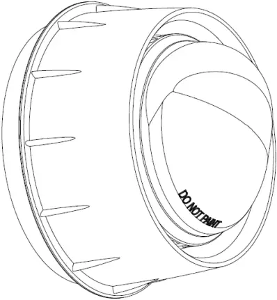
 INSTALLATION / PRODUCT ORIENTATION
Affix B501AP to a suitably flat wall. Terminate the cable to the appropriate terminals. For surface mount wiring the cable can enter the B501AP via the break outs provided. Select the appropriate Light Coverage, Tone and Volume settings via the DIP switch.
Make sure the product is fitted in the correct orientation!
Scan the barcode below to see the correct fitting to the wall:

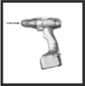
 CONTINUITY SPRING
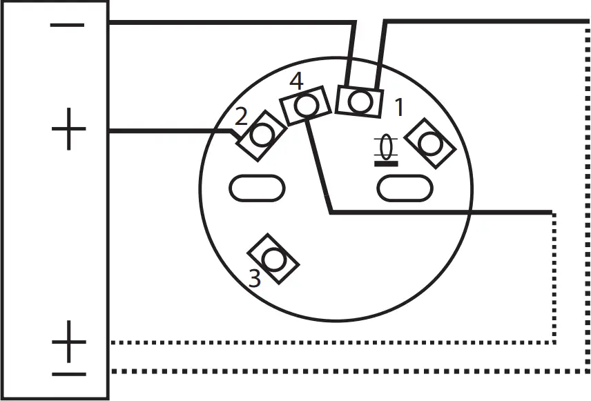
The B501AP incorporates a continuity spring between terminals 2 and 4. This allows the continuity of the field wiring to be checked without the need for the device to be present. Inserting the device will disengage the spring.
Removing the device will close the loop.
 TERMINAL CONNECTIONS
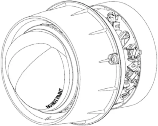
 ANTI TAMPER RELEASE
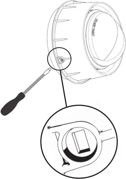
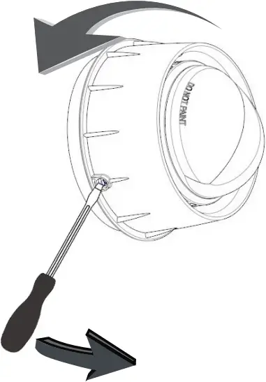
IMPORTANT: Follow the instruction strictly:
1) Insert a flat screwdriver
2) Lever the screwdriver down and twist the device anticlockwise.
3) Remove the screwdriver to unlock the device.
For a full video on how to release the anti-tamper feature please scan the QR code:

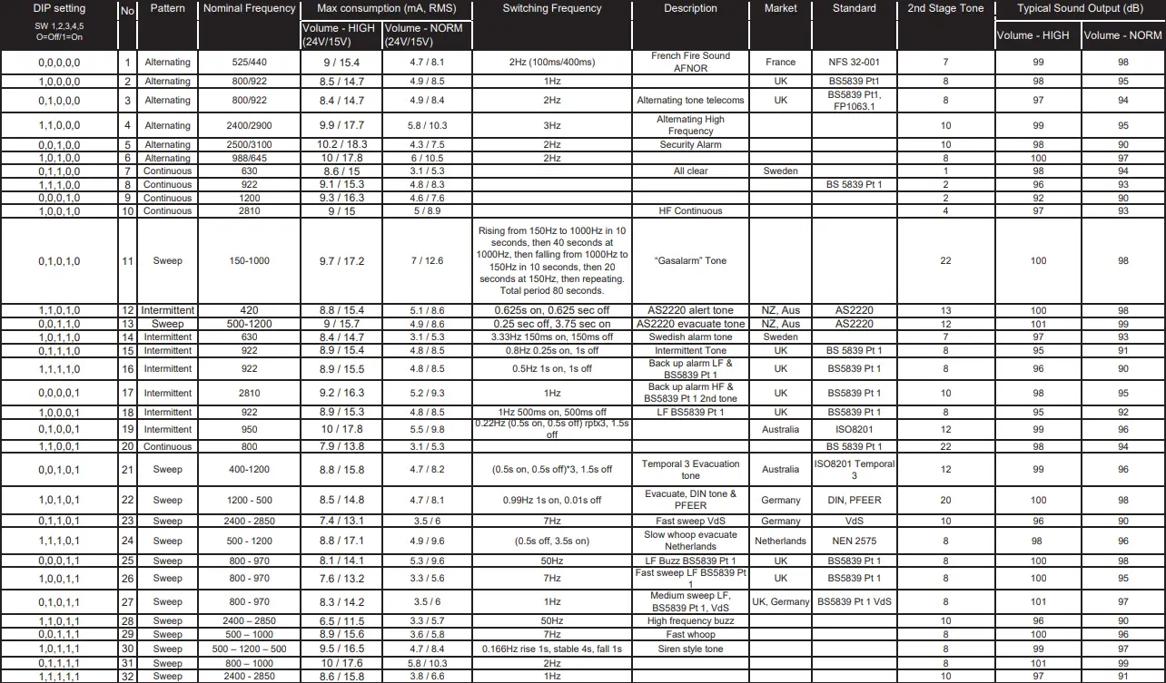
Table 1 (Tone selection)
Address settings
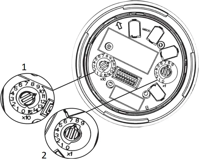
S1 S2
Address 108 = 10 8
- Switch 1
- Switch 2
To set one of the 159 available addresses for the device use the two rotary switches located either side of the dip switch unit. The ‘tens’ digits goes from 0 to 15 and the ‘units’ from 0 to 9. *100 – 159 Only available with advanced protocol.
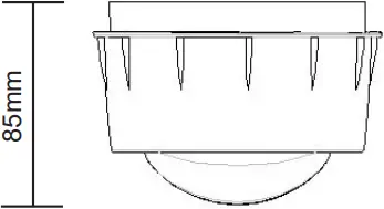
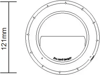
Dimensions
Volume, coverage and frequency settings
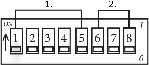
- (Refer to table 1 )
- (Refer to table 2 )
DIP setting 0=Off/1=On.
Table 2
| ON | OFF | ||
|
SW6 |
LOW VOLUME | HIGH VOLUME | |
|
SW7 |
0.5Hz Red (W-2.4-10.5/W-3.6-10.5) White (W-2.4-9/W-3.8-9) |
0.5Hz Red (W-2.4-11.5/W-4.2-11.5) White (W-2.4-11.5/W-4-11.5) |
|
|
SW8 |
f |
1Hz (O-2.4-3) | 0.5Hz (EN54-23 W Class) |
Coverage data
|
EN 54-23 |
Led | V | X (Max) | Y (Max) | V (m ³) |
| W-4.2-11.5 W-2.4-11.5 |
RED | 15-29V | 4.2m 2.4m |
11.5m 11.5m |
555 317 |
| W-3.6-10.5 W-2.4-10.5 |
RED | 15-29V | 3.6m 2.4m |
10.5m 10.5m |
397 265 |
| O – 2.4 – 3 | RED | 15-29V | 2.4 | 3m | 21.6 |
| W- 4 -11.5 W- 2.4-11.5 |
WHITE | 15-29V | 4m 2.4m |
11.5m 11.5m |
529 317 |
| W-3.8-9 W-2.4-9 |
WHITE | 15-29V | 3.8m 2.4m |
9m 9m |
308 194 |
| O – 2.4 – 3 | WHITE | 15-29V | 2.4 | 3m | 21.6 |
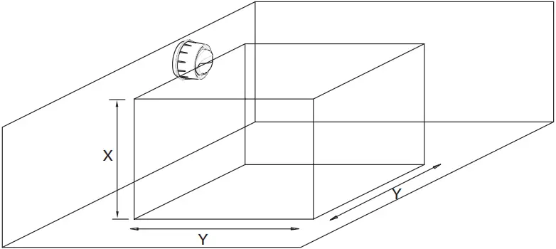
For the ‘O’ class detailed coverage data, in accordance with EN54-23, please request the following doc.: S00-7006
2831 23 0832 23 |
| Morley IAS by Honeywell, Pittway Tecnologica Srl, Via Caboto 19/3, 34147 Trieste, ItalyDOP050 |
| EN 54-3:2001 +A1: 2002 + A2:2006 Fire detection and fire alarm systems – SoundersEN54-23:2010 Fire detection and fire alarm systems – Visual Alarm DevicesEN 54-17:2005 Fire detection and fire alarm systems – Short-circuit isolators.W*A-*C-I05 |
For LPCB: approved to EN 54-3: 2014 + A1: 2019.
Sounder Output data, in accordance with EN54-3, is available on Document Ref: S00-7005
I56-5003-000